Table of Contents
Advertisement
Quick Links
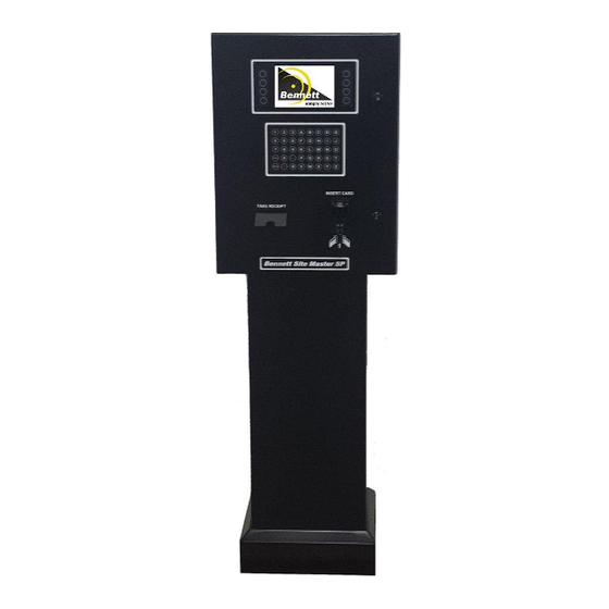
Site Master SP
(Large Display w/ SBC2)
Programming, Service, and Parts Manual
132382 Rev B 10/23/17
Only Trained Personnel May Work on This Equipment
READ THIS MANUAL
This manual has important information for safe installation and operation of this equipment. Read and understand
this manual before applying power. Keep this manual and tell all service personnel to read this manual. If you do not
follow the instructions, you can cause bodily injury, death, or damage to the equipment.
Bennett 1218 E. Pontaluna Road, Spring Lake, MI 49456
USA 800-235-7618 ~ Outside USA 231-798-1310
sales@bennettpump.com ~ www.bennettpump.com
Advertisement
Table of Contents

Related Manuals for Bennett Site Master SP

Summary of Contents for Bennett Site Master SP
- Page 1 Keep this manual and tell all service personnel to read this manual. If you do not follow the instructions, you can cause bodily injury, death, or damage to the equipment. Bennett 1218 E. Pontaluna Road, Spring Lake, MI 49456 USA 800-235-7618 ~ Outside USA 231-798-1310...
- Page 2 The material included in this installation manual is accurate at the date of publication. The intent of this manual is to assist. If further assistance is required, please contact the Bennett Technical Service Department at 1-800-423-6638. Bennett Marketing Services can be contacted by mail, facsimile, telephone or e-mail at the locations specified below: Bennett Pump Company...
- Page 3 Bennett 1218 E. Pontaluna Road, Spring Lake, MI 49456 USA 800-235-7618 ~ Outside USA 231-798-1310 sales@bennettpump.com ~ www.bennettpump.com...
- Page 4 Bennett 1218 E. Pontaluna Road, Spring Lake, MI 49456 USA 800-235-7618 ~ Outside USA 231-798-1310 sales@bennettpump.com ~ www.bennettpump.com...
-
Page 5: Table Of Contents
Site Master Large Display w/ SBC2 Programming, Service, and Parts Manual Table of Contents Table of Contents Bennett Limited Warranty for Product Installed in the United States – Site Master Bennett Limited Warranty for Product Installed in Canada – Site Master PCI SSC Legal Terms and Conditions... - Page 6 Site Master Large Display w/ SBC2 Programming, Service, and Parts Manual Table of Contents Table of Contents Managers Mode 06 – Keypad Diagnostics ................................ 34 Managers Mode 07 - Peripheral Power Resets ..............................34 Managers Mode 08 – Software Version ................................35 Managers Mode 09 –...
-
Page 7: Safety Instructions
Maintenance repairs must be done by authorized personnel only. Warranty work may only be performed by Bennett certified technicians. To prevent electric shock, keep the electrical parts of the Site Master dry. - Page 8 Environmental Standards® Health, Safety, Security & Environment (HSSE) policies. Note: Bennett Pump highly recommends all technicians observe HSSE policies defined by the supplier. Bennett Pump does not impose any restrictions or additional requirements contained in Environmental Standards® Health, Safety, Security & Environment (HSSE) policies.
-
Page 9: Introduction
OFF POSITION. MAINTENANCE MUST BE PERFORMED BY TRAINED PERSONNEL ONLY. Bennett Pump Company products are designed to meet or exceed the standards of UL, FCC and the National Institute of Standards and Technology. Compliance with these standards protect the operator and the consumer from personal injury and ensure an accurate delivery of product. -
Page 10: Abbreviations And Acronyms
Site Master Large Display w/ SBC2 Programming, Service, and Parts Manual Introduction Introduction Abbreviations and Acronyms Term Description Alternating Current Central Processing Unit Direct Current Federal Communications Commission Hertz International Fire Code National Electrical Code NIST National Institute of Standards and Technology Number Payment Card Industry Point of Sale... -
Page 11: General Operation & Overview
Site Master Large Display w/ SBC2 Programming, Service, and Parts Manual General Operation & Overview General Operation & Overview Exterior Layout 7” Display Alpha-Numeric Keyboard Key Locks Receipt Printer Card Reader Figure 1.1 - Exterior Layout... -
Page 12: Interior Layout
Site Master Large Display w/ SBC2 Programming, Service, and Parts Manual General Operation & Overview General Operation & Overview Interior Layout 120VAC is installed in the head of the unit and terminated on the terminal strip as shown in Figure 1.2. Neutral and Hot are labeled on the terminal strip. -
Page 13: Powering Up The Module
When power is applied to the Site Master, the Bennett Logo will appear for approximately 3 seconds as shown in Figure 1.4. After the Bennett Logo is displayed, the idle screen will be displayed as shown in Figure 1.3. - Page 14 Site Master Large Display w/ SBC2 Programming, Service, and Parts Manual General Operation & Overview Page Intentionally Left Blank...
-
Page 15: Installation
Follow the procedure below for mounting instructions. Refer to the Site Master SP Footprint Diagram (125927 – P4208) shown on the next page or on the USB provided located inside the unit for conduit connections for the Site Master. -
Page 16: Site Master Sp Footprint
Site Master to make electrical connections. Shims should only be used under bolts to ensure the Site Master is level. Improper shimming that result in misaligned frames is NOT covered under the Bennett Limited Warranty. Side 2 (Back) Side 1 (Front) - Page 17 Site Master Large Display w/ SBC2 Programming, Service, and Parts Manual Installation Installation Figure 2.3 - Side View Dimensions Figure 2.2 - Front View Dimensions...
-
Page 18: Determining The Number Of Wires Required
RS-485 wires should be twisted together no less than 3 turns per foot to reduce the effects of electrical noise on the communication circuit. Due to the risk of noise, causing possible problems with communication, Bennett highly recommends the use of twisted wires, but does not require it. Note: Belden shielded cable is accepted but the “drain”... -
Page 19: Beginning The Wiring Process
Installation WARNING: FAILURE TO PROPERLY GROUND THE EQUIPMENT CAN CAUSE INJURY OR DAMAGE TO THE EQUIPMENT AND WILL VOID THE BENNETT LIMITED WARRANTY. WARNING: DO NOT TERMINATE AT THE NEUTRAL BAR OF A SUB-PANEL OR RELY ON METAL CONDUIT FOR THIS GROUND CONNECTION. EACH SITE MASTER’S GROUNDING POST MUST BE WITHIN 1-OHM RESISTANCE TO EARTH GROUND POTENTIAL. -
Page 20: Wiring Diagrams
Refer to the Wiring Diagrams (126000 – P4229s1 and P4229s2) located inside the Site Master or on the USB provided. AC Power Connections for Site Master SP Read all safety instructions and notes shown in Figure 2.3 before applying power to the Site Master. - Page 21 Site Master Large Display w/ SBC2 Programming, Service, and Parts Manual Installation Installation RS-485 Communication Protocol for Site Master SP Read all safety instructions and notes shown in Figure 2.4 before applying power to the Site Master. NOTES FOR COMMUNICATION WIRING DIAGRAM All wiring must be installed and used in accordance with the national electrical code (NFPA #70, Automotive and marine service code NFPA #30A), state, and local electrical codes.
-
Page 22: Connector Descriptions
Site Master Large Display w/ SBC2 Programming, Service, and Parts Manual Installation Installation Connector Descriptions DANGER: POWER MUST BE OFF TO THE SITE MASTER AND THE BATTERY DISENGAGED PRIOR TO PLUGGING ANYTHING INTO OR UNPLUGGING ANYTHING FROM THIS MODULE. DANGER: WHEN INSERTING THE PLUGS INTO THE CONNECTORS, MAKE SURE THAT THE LOCKING TAB POINTS TO THE CORRECT SIDE OF THE CONNECTOR. -
Page 23: Programming
Site Master Large Display w/ SBC2 Programming, Service, and Parts Manual Programming Programming The module uses manager’s modes that are used to access programming and diagnostics. The following instructions explain how to gain access to the Managers Mode and how to configure it for operation. Note: The EMV Card Reader is not available for the Site Master. -
Page 24: Gaining Access To Managers Mode 00
Site Master Large Display w/ SBC2 Programming, Service, and Parts Manual Programming Programming Gaining Access to Managers Mode 00 The Soft Keys on the right hand side of the display are the only keys used to enter into Managers Mode. The top Soft Key on the right is 1 and the bottom Soft Key on the right is 4. -
Page 25: Managers Mode 00 - Line Descriptions
Site Master Large Display w/ SBC2 Programming, Service, and Parts Manual Programming Programming Programming Managers Mode 00 – Line Descriptions Managers Mode 00 is used to display diagnostic information for the CAT protocol as shown in Figure 3.4. The following is a description of what each line represents on the display. Note: If the module remains in Managers Mode for 60 seconds without any keys pressed, the unit will automatically return to normal operation. -
Page 26: Managers Mode 01 - Address
Site Master Large Display w/ SBC2 Programming, Service, and Parts Manual Programming Programming Managers Mode 01 – Address To set the fueling point address, follow this procedure: In Managers Mode 00, press the numeric [1] key and press the function [Enter] key. Once the [Enter] key is pressed, the display will show the current fueling point it is currently configured for as shown in Figure 3.5. -
Page 27: Managers Mode 12 - Receipt Length
Site Master Large Display w/ SBC2 Programming, Service, and Parts Manual Programming Programming Managers Mode 12 - Receipt Length To help eliminate paper jams, Managers Mode 12 will adjust the length of the receipts. It is highly suggested that the length of the receipt is configured so the end of the paper will exit the chute with the least amount of paper. -
Page 28: Managers Mode 13 - Payment Keypad Type
Figure 3.10. Press the soft key where [Next Card Reader] is present to cycle through available card readers described below. Bennett SCR- 5 x 8 used when using alphanumeric characters for credit / fleet operations UIC MSR280 – 4 x 4 used for credit only! ... -
Page 29: Managers Mode 14 - Receipt Delay
Site Master Large Display w/ SBC2 Programming, Service, and Parts Manual Programming Programming Managers Mode 14 - Receipt Delay As the POS sends data to the module for the receipts, the data is broken up in small increments. At times, this can cause the printer to have slight pauses while printing the receipts. -
Page 30: Managers Mode 17 - Select Feature Media
PROMO Reel Trigger – TBD IDLE Reel Trigger – TBD Flash – Select Flash Frames associated with the reel. Note: Contact the Bennett Technical Support Group at 1-800- 423-6638 to find flash ID. Fuel – Edit fuel events is not enabled at this time. -
Page 31: Managers Mode 18 - Pin Pad Cancel Enable Or Disable
Managers Mode 18 is used to print configuration log and allow or block the cancel key on the PIN pad. Note: The PIN Cancel BLOCKED option must be selected for Passport point of sale systems. Call Bennett Technical Support at 1-800- 423-6638 for more information. -
Page 32: Managers Mode 19 - Display Configuration And Diagnostics
Managers Mode 19 - Display Configuration and Diagnostics CAUTION: DO NOT ENTER MANAGERS MODE 19 UNLESS INSTRUCTED BY THE BENNETT TECHNICAL SUPPORT GROUP. Managers Mode 19 is used to calibrate the display, run a diagnostics report, clear flash frames, and select media options. - Page 33 Site Master Large Display w/ SBC2 Programming, Service, and Parts Manual Programming Programming Follow the instructions below to access the available options. Screen Calibration Note: The device will restart after selection is made. To calibrate the 7” Display (800 x 480) or the 10.4” Display (800 x 600), follow this procedure. In Managers Mode 00, press the number [1] and [9] keys and then press the function [Enter] key to enter the SBC Main Menu.
- Page 34 Normal Media – The inset video Idle reel is triggered by “Welcome” and full screen full reel is triggered by “Promo” text. Showing PROMO Reel – Do not use. For Bennett Use Only! Showing WELCOME Reel – Do not use. For Bennett Use Figure 3.21 – Media Only! Media Disabled –...
-
Page 35: Diagnostics
Site Master Large Display w/ SBC2 Programming, Service, and Parts Manual Diagnostics Diagnostics How to Use Diagnostics Diagnostic tests have been programmed into the software to help the operator and service technician to troubleshoot failures of the module. The module can run several levels of self-diagnostic tests to determine where the failure has occurred. -
Page 36: Managers Mode 02 - Real Time Clock (Rtc)
Site Master Large Display w/ SBC2 Programming, Service, and Parts Manual Diagnostics Diagnostics Managers Mode 02 – Real Time Clock (RTC) Manager Mode 02 is uses a Real Time Clock (RTC) that the module uses to track software restarts, real time clock changes, and door open alarm Audit Events. -
Page 37: Managers Mode 03 - Audit Trail Report
Site Master Large Display w/ SBC2 Programming, Service, and Parts Manual Diagnostics Diagnostics Managers Mode 03 – Audit Trail Report After the Real Time Clock has been set, the Audit Trail Report will print the date and time that each event happens. These reports will tell when each of the Audit Events have taken place. - Page 38 Site Master Large Display w/ SBC2 Programming, Service, and Parts Manual Diagnostics Diagnostics Report Examples The following reports tell when each of the audit events have taken place. Audit Events Report The Audit Events Report shows the last 25 events that took place. Notice in Figure 4.5 that the event column (left side of report) reflects the three different types of events.
- Page 39 Site Master Large Display w/ SBC2 Programming, Service, and Parts Manual Diagnostics Diagnostics Door Open Alarms Report (Optional) The Door Open Alarms Report reflects the last 21 times that the door alarm went off. It has not reached the maximum 25 number of events.
-
Page 40: Managers Mode 04 - Card Reader Diagnostics
Site Master Large Display w/ SBC2 Programming, Service, and Parts Manual Diagnostics Diagnostics Managers Mode 04 – Card Reader Diagnostics This mode is used to test the card reader for the module. When the Waiting for card reader module enters into the mode, it will send a signal to the card reader to see if it is acknowledged and if the tracks are operational. -
Page 41: Managers Mode 05 - Printer Diagnostics
Site Master Large Display w/ SBC2 Programming, Service, and Parts Manual Diagnostics Diagnostics Managers Mode 05 – Printer Diagnostics This mode is used to test the printer and to determine if the data is being received from the printer. To test the printer, follow this procedure: In Managers Mode 00, press the numeric [5] key and press the function [Enter] key. -
Page 42: Managers Mode 06 - Keypad Diagnostics
Site Master Large Display w/ SBC2 Programming, Service, and Parts Manual Diagnostics Diagnostics Managers Mode 06 – Keypad Diagnostics This mode is used to test every key on the module including the left and right soft keys. To test the keys on the module, follow this procedure: In Managers Mode 00, press the numeric [6] key and press the function [Enter] key. -
Page 43: Managers Mode 08 - Software Version
The display will prompt to press [1] and [Enter] to restart the software or press EXIT to leave the mode as shown in Figure Figure 4.17 – Bennett SCR Software Version 4.19. If the numeric [1] key and function [Enter] key is pressed, the software and display will automatically reset. -
Page 44: Managers Mode 10 - Maximum Queues
Site Master Large Display w/ SBC2 Programming, Service, and Parts Manual Diagnostics Diagnostics Diagnostics Diagnostics Diagnostics Managers Mode 10 – Maximum Queues This mode is used to display the maximum queues. Note: This is for Diagnostic and Development purposes only! To view the maximum queues, follow this procedure: In Managers Mode 00,, press the numeric [1] and [0] keys and press the function [Enter] key to view the Maximum Queues as... -
Page 45: Service
For information on parts, please refer to the Parts Section. The service information in this manual is intended for Bennett trained technicians. All technicians must be aware of all safety instructions provided on page iii. If you are not a Bennett trained technician, please contact Bennett Technical Support at 1-800-423-6638 for training information. - Page 46 2 (black) OUT - negative Micro SD Card A MicroSD Card slot is used for software upgrades. Contact Bennett Technical Support at 1-800-423-6638 before use. Indicators (Buzzer / Printer Handshake Communication) An 8-pin terminal plug is used to connect to a buzzer and printer communication. Note: The +12v on Pins 1, 2, and 3 is the same +12v that enters the CPU Board on Pins 1 and 2 of J5.
- Page 47 Site Master Large Display w/ SBC2 Programming, Service, and Parts Manual Service Service Service Card Reader Communication This is dedicated to RS-232 used to interface the card swipe reader. A D-Sub 9-pin connector serial communication interface port. A DB-9 (DE-9) cable is used to connect to the J6 connector of SBC2 Board for payment terminal communication.
- Page 48 Site Master Large Display w/ SBC2 Programming, Service, and Parts Manual Service Service LCD Display and Fan Assembly Power Used to provide power to the LCD display fan assembly through a 6-position header. Description Description 1 (orange) +24V DC Supply Voltage +V5A +24V DC Supply Voltage Ground...
- Page 49 Site Master Large Display w/ SBC2 Programming, Service, and Parts Manual Service Service Color Description Green “Happy/Watchdog Heartbeat” – Blinks at the rate of one time per second when in normal run mode. Receive Data (J8 – Receipt Printer) Green Transmit Data RS-485 (J8 –...
-
Page 50: Power Supply Board
Site Master Large Display w/ SBC2 Programming, Service, and Parts Manual Service Service SBC2 Electronics 10-position header input connects to the SBC2 Electronics for Module Power and Module RS-485 Payment Communication. Replacing Fuses CAUTION: Replace fuses only with fuses of the same rating. If the incoming AC voltage blows a fuse on the power board, check for cross phasing. -
Page 51: Sbc2 Payment Block Diagram
Site Master Large Display w/ SBC2 Programming, Service, and Parts Manual Service Service Component Description The following is a description of the connections to the terminal strips of all the connections used on the power supply board as shown in Figure 5.5. Power Board A 5-position header input connects to the power board for +24VDC and +12VDC. -
Page 52: Hengstler Printer (135449S)
Site Master Large Display w/ SBC2 Programming, Service, and Parts Manual Service Service Hengstler Printer (135449s) The Hengstler printer shown in Figure 5.6 is primarily used for printing receipts. Note: It is suggested that Managers Mode 12 (Receipt Length) be configured after the first receipt is printed. The length of the receipt will vary, depending on the information sent from the Point of Sale. - Page 53 If the chute has been obstructed due to vandalism, the chute will have to be dismounted and cleaned. Contact Bennett Pump Technical Support at 800-423-6638 for additional information. In case there is still paper between the printhead and the platen, remove the friction between head and platen by pressing down the lever and then pull the paper back by hand as shown in Figure 5.7.
- Page 54 Site Master Large Display w/ SBC2 Programming, Service, and Parts Manual Service Page Intentionally Left Blank...
-
Page 55: Parts
To place an order for parts please contact us by mail, email, phone, fax, or web using the information provided below. Note: Verbal orders cannot be accepted. A signed purchase order must be faxed or emailed to the Bennett Order Entry Department at 231-799-6202 or customerservice@bennettpump.com. -
Page 56: 7" Alpha Numeric Payment Panel Assembly
Site Master Large Display w/ SBC2 Programming, Service, and Parts Manual Parts Parts 7” Alpha Numeric Payment Panel Assembly Refer to the 7” Alpha Numeric Payment Panel Assembly Parts Lists on page 37 for part number, description, and quantity. Figure 6.2 - 7" Display Parts Breakdown... -
Page 57: 7" Alpha Numeric Payment Panel Assembly Parts List
Site Master Large Display w/ SBC2 Programming, Service, and Parts Manual Parts Parts 7” Alpha Numeric Payment Panel Assembly Parts List Refer to the 7” Alpha-Numeric Payment Panel Assembly on page 36 for reference number locations. Notes: Not all parts are shown. ... -
Page 58: Sbc2 Circuit Board Wire Harness Connections
Site Master Large Display w/ SBC2 Programming, Service, and Parts Manual Parts Parts SBC2 Circuit Board Wire Harness Connections Refer to the SBC2 Circuit Board Wire Harness Connections Parts Lists on pages 39 through 40 for part number, description, and quantity. Figure 6.3 –... -
Page 59: Sbc2 Circuit Board Wire Harness Parts List
Site Master Large Display w/ SBC2 Programming, Service, and Parts Manual Parts Parts SBC2 Circuit Board Wire Harness Parts List Refer to the SBC2 Circuit Board Wire Harness Connections on page 46 for reference number locations. Notes: Not all parts are shown. ... - Page 60 Site Master Large Display w/ SBC2 Programming, Service, and Parts Manual Parts Parts Ref. No. Part No. Description Qty. Picture Card Reader Cable (Comes with Card Reader 114131) 124299 Display Fan Assembly and Harness 113533 Cable HECON Printer RS232 (comes with printer kit) 128494 Cable USB Extension Panel Mount...
- Page 61 Site Master Large Display w/ SBC2 Programming, Service, and Parts Manual Parts Parts Ref. No. Part No. Description Qty. Picture 118553 Soft Key Wire Assembly B- SPM Ribbon Cable 118553 Soft Key Wire Assembly B- SPM Ribbon Cable 135451 Cable HECON Printer Power Harness 131757 Cable Display KYOC.
-
Page 62: Printer Kits
Site Master Large Display w/ SBC2 Programming, Service, and Parts Manual Parts Parts Printer Kits Notes: Not all parts are shown. The quantity may vary based on the options ordered for your Site Master. Use Part Number 135449s if replacing Part Number 113606. ... -
Page 63: Site Master Spare Parts List
Site Master Large Display w/ SBC2 Programming, Service, and Parts Manual Parts Parts Notes: Many electronic circuit boards have a factory-rebuilt equivalent. All rebuilt boards have a part number prefix of “RB”. You must use factory-rebuilt parts for all warranty service work. Please refer to the Distributor Policy Manual for program terms and details. - Page 64 Bennett 1218 E. Pontaluna Road, Spring Lake, MI 49456 USA 800-235-7618 ~ Outside USA 231-798-1310 sales@bennettpump.com ~ www.bennettpump.com...
Need help?
Do you have a question about the Site Master SP and is the answer not in the manual?
Questions and answers