Table of Contents
Advertisement
Advertisement
Table of Contents

Summary of Contents for GEISMAR STUMEC MIW.3
- Page 1 MIW.3 ANGLAIS PORTABLE MOTOR IMPACT WRENCH MIW.3...
- Page 3 GEISMAR, the quality choice ! You have just acquired a machine for laying and servicing railway lines. We thank you for choosing equipment developed and constructed by GEISMAR / STUMEC, the fruit of over eighty years’ experience. Every day since 1924, the GEISMAR Group has been investing in research and state-of-the-art construction to offer you the quality and reliability so essential to the requirements of the world of railways.
-
Page 4: Table Of Contents
General safety instructions 5.1.2 Cleaning Particular safety instructions 5.1.3 Tightening 5.1.4 Carburettor 1.4.1 Risks that may arise from using the MIW.3 portable power 5.1.5 Spark arrester grille on silencer wrench 5.1.6 Spark plug 1.4.2 Personal protective equipment 5.1.7 Reducer and shock absorber 1.4.3 Handling fuel... -
Page 5: Chapter 1 - Safety
CHAPTER 1 – SAFETY 1.1 Foreword The following set of rules has been drawn up to ensure the application of precautionary principles that help to preserve the safety of persons and property when the machine is in use. Any failure to comply with these rules can have serious repercussions (bodily injury, etc.), and can even be fatal, so we must draw your attention to the fact that all persons involved in the use, maintenance, storage or custody of the machine covered by the present manual must be familiar with these rules. -
Page 6: General Safety Instructions
1.3 General safety instructions • The operator and the working environment To avoid all risks of accident or injury, it is essential to wear: - Sturdy, non-flammable clothing that is suitably close-fitting - Strong, non-slip gloves - Safety shoes - Protective eyewear - Safety helmet - All other equipment necessary on the site or when using the machine In the case of use of ear defenders, the safety instructions in force on the site must be complied with at all times. - Page 7 • The operator and the machine Before putting the machine into service each time, check that its condition and its operation are in compliance with the instructions. In particular, make sure that the controls are free and in good working order, and that they are in the “stop” or “neutral” position. Never make any modifications that could affect correct operation of the control systems.
- Page 8 • Using and handling fuel and oil It is essential to stop the engine and set the control to the stop position before carrying out any work involving fuel (filling up, checking the level, draining, etc.). Always keep suitable extinguishers ready for use in all areas where fuel is handled (storage, filling up, etc.). Always store fuel and oil in separate cans specially designed for the purpose and bearing the labels required by regulations.
- Page 9 • Tools to be used on the machine Use only the types of tools intended for normal use of the machine. Measure the speed of all rotating tools at regular intervals. Never use tools at speeds greater than the maximum speed for which they have been designed and approved. Never use damaged tools or tools that have reached their maximum level of wear.
-
Page 10: Particular Safety Instructions
1.4 Particular safety instructions 1.4.1 Risks which may be engendered by the use of MIW.3 • The use of ear protection is also recommended (strictly portable power wrench complying, however, with the applicable railway regulations applicable on the site in order to... -
Page 11: Transport - Handling
1.4.4 Transport - Handling • As soon as the engine starts, it produces toxic exhaust • Never transport the machine with the engine running, even at idling gases. These gases may be odourless and invisible. speed. Never work with the machine in enclosed or poorly •... -
Page 12: Chapter 2 - Description Of The Machine
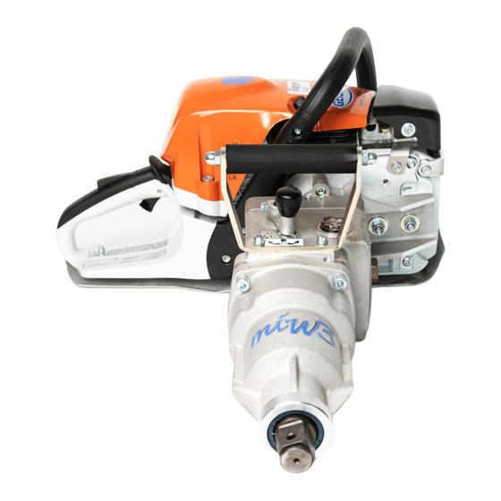
Light and compact, the machine is easily carried and manipulated by a single operator. Ease of use and low vibration (in spite of its robustness and high power) make the MIW.3 the ideal choice for work on railway sites. The MIW.3 portable power wrench is powered by an air-cooled 2-stroke engine with a centrifugal clutch, an all-position membrane carburettor and built-in fuel pump, and electronically-controlled magneto ignition. - Page 13 2.2 General view Designation Rear hand protector Rear handle Air filter cover Tubular front handle Exhaust silencer with exhaust shield 1” (25.4 mm) square drive Impact device Rotation speed reducer Oil drain-refill plug Oil level indicator Front handle Reverse lever Accelerator trigger lock Starter handle Air filter cover screw...
-
Page 14: Technical Characteristics
2.3 Technical characteristics Dimensions Engine Length / width / height ……..…….………..650 / 450 / 275 Type ……………………………….. …….. STIHL MS 311 Cubic capacity ……………………... cm³ Weights Machine (empty) …………........19.1 Power (@ 9500 rpm) ……….……... Cylinder bore ……..………………. Machine (in running order) ……......20.3 Maximum speed*..…………….. - Page 15 2.4 Position of the machine relative to the track The diagram below shows the dimensions of the machine with respect to the UIC 505-1 standard (nominal rail separation = 1435 mm). MIW3_Gb_01161_130204.doc...
-
Page 16: Chapter 3 - Installation - Utilisation
CHAPTER 3 – INSTALLATION – UTILISATION 3.1 Fitting the socket The operations involved in fitting and removing the socket must be performed with the engine stopped. When changing a socket, never replace the cylindrical pin by a protruding fixing object (nail, metal wire, etc.) which could trap and drag the operator’s clothing and cause injury. -
Page 17: Filling With Fuel
only use good-quality engine oil intended for air-cooled two-stroke engines. It is preferable to use STIHL oil for two-stroke engines, which is • Engine oil specially made for STIHL engines and guarantees long engine life. Do not use oil intended for water-cooled engines, nor oil for 4-stroke engines. For machines with exhaust catalysers, prepare the mixture only with STIHL 2-stroke engine oil at a ratio of 1:50. -
Page 18: Inspecting The Machine
• Opening the cap Take hold of the folding handle and raise it to the vertical position (Fig.1). Fig.1 Fig.2 Turn the cap fully anticlockwise (approximately ¼ of a turn) (Fig.2). The mark on the tank cap and the “open position” symbol marked on the machine must coincide. Remove the tank filler cap (Fig.3). -
Page 19: Chapter 4 - Utilisation
• Checking the fuel level (this check is done with the engine stopped) - Check the fuel level and top up if necessary ( : be sure to refer to 1.3 “General safety instructions” / “Utilisation and handling of fuel” and 3.2.2 “Filling with fuel”). - Page 20 4.2 Using the machine Positions of the universal lever = Stop engine – ignition off. = Normal working position – the engine is running or is able to start. To move the universal lever from the position to , push simultaneously the accelerator trigger lock and the accelerator trigger.
- Page 21 Accelerate slightly for a few moments to allow the engine to warm up. To facilitate engine starting and avoid the risk of accidents, the lower part of the machine must be resting on the ground. If appropriate, make the adjustment for winter use (see “winter use”). Push down the button to open the If the engine does not start at the first attempt, the universal control...
- Page 22 Never do tightening or releasing work before the engine is warm Tightening operation Bring the reverser lever to the tightening position (to the right). Place the machine in position on the bolt or lag screw, holding it vertically in both hands, one on the handle with the accelerator lever and the other on the tubular front handle (utilisation in vertical position).
- Page 23 Winter use 洪 Set the universal control lever to the stop position 0 浩 Undo the screws 会 and remove the cover 解. For temperatures below +10 °C Pull out the slider 回 from the (summer use) position. Fit the slider in the (winter use) position with symbol facing up Replace the cover and tighten the screws firmly.
-
Page 24: Storage
4.3 Storage 4.2.2 Particular instructions for storage 4.3.1 General instructions for storage If work is to be interrupted for more than a week: During prolonged periods of non-use of the machine, it must be stored in order to protect its integrity. Equipment which has been incorrectly Empty the fuel tank into a container in a well-ventilated place. -
Page 25: Chapter 5: Servicing And Maintenance
CHAPTER 5: SERVICING AND MAINTENANCE 5.1 Servicing This equipment must only be serviced and repaired by persons with the required training, skills and tools. Equipment servicing and repair must only be carried out by competent persons with good general mechanical knowledge. Stop the engine before any servicing work (leave the control in the Stop position) and wait for it to cool down. -
Page 26: Carburettor
5.1.4 Carburettor When the machine leaves the factory, the carburettor is optimally adjusted according to the barometric and meteorological conditions prevailing on the site of the production plant. Apart from routine maintenance during use, it is advisable for carburettor repairs or adjustments to be carried out by personnel from the GEISMAR / STIHL sales or repair network. - Page 27 If the idling speed is irregular or acceleration is unsatisfactory: the idling adjustment is too weak. Turn the idling mixture screw anticlockwise until the engine runs evenly and acceleration is normal. After each adjustment of the idling mixture screw, the idling speed stop screw LA generally also requires adjustment. Correcting the carburettor adjustment for working at high altitude if the engine does not run satisfactorily Turn the high speed mixture screw clockwise (to weaken the mixture) to the limit against the stop.
-
Page 28: Spark Plug
5.1.6 Spark plug If the engine lacks power, is difficult to start or idles unevenly, the first check must always be the condition of the plug. Place the universal control lever in the 0 position. Undo the screws and remove the cover Disconnect the ignition cable from the plug by pulling it backwards. - Page 29 5.1.7 Reducer and impact system Lubrication: Oil-bath lubrication is used, offering a number of advantages: better lubrication than with grease, which may be ejected from the working surfaces of the mechanism. good heat dissipation and attenuation of the noise generated by the impact mechanism. Filling and draining via the plug 会.
- Page 30 5.1.8 Dismantling the impact mechanism WARNING - At this point, there is nothing to retain the ball bearings in the stop The damping washer (Ref. 56141) is a component subjected to high mechanical loads and therefore needs to be replaced at intervals. This Fig.3 Fig.4 Fig.4...
-
Page 31: Replacing The Starter Cord
5.1.9 Replacing the starter cord Remove the cover Set the universal control lever to the stop position "0". Undo the screws and remove the cover Remove the fan cover: Undo the screws Separate the lower section of the fan cover from the crankcase cover and remove the fan cover from below. -
Page 32: Tension Of Return Spring
5.1.10 Tension of return spring Make a loop with the unwound part of the starting cable and use the loop to turn the cable pulley six turns in the direction of the arrow. Holding the cable pulley, pull the twisted cable towards the outside and put it back in order. Release the pulley. -
Page 33: Filtration System
5.1.12 Filtration system A clogged filtration system may give rise to the following problems: - abnormal fuel consumption. - engine starting difficulties. - a drop in engine power. Fig.1 - premature engine wear. At the end of each working day (See Fig.1): Fig.2 Set the universal control lever to the stop position "0". -
Page 34: Suction Strainer
5.1.13 Suction strainer The suction strainer is located inside the fuel tank. It should be replaced if clogged, or at least once per year. Drain the fuel tank. Take the suction strainer out of the tank, using a hook, and pull it off the flexible pipe. Insert the new suction strainer in the flexible pipe. -
Page 35: Maintenance
5.2 Maintenance 5.2.1 Preventive maintenance schedule FREQUENCY Component NATURE OF OPERATION Reference Inspect the machine Chap.3 - § 3 Complete machine Carry out general cleaning with a clean cloth or a Chap.5 § 1.2 blower to remove deposits of dirt from the machine Control devices Check operation Chap.3 §... - Page 36 FREQUENCY COMPONENT NATURE OF OPERATION Reference Check oil level Impact system Chap.5 § 1.7 Change oil Chap.5 § 1.9 Starting cable Replace Chap.5 § 1.11 Return spring Replace Chap.5 §1.8 Damping washer Replace Clean filter box and surrounding area Filtration system Chap.5 §...
-
Page 37: List Of Normal Wearing Parts
5.2.2 List of normal wearing parts The following list specifies the normal wearing parts in the machine and the conditions for their replacement. It is important, however, to replace or repair immediately any worn, damaged or missing part if there is a risk for safety. Designation Replacement conditions Drive nose... -
Page 38: Chapter 6 - Accessories And Options
CHAPTER 6 – ACCESSORIES AND OPTIONS 6.1 Optional equipment 6.1.1 Protected equipment for drilling sleepers (EEC compliant) A device for drilling sleepers (Ref. 56000 AS) can be fitted to the output shaft of the portable power wrench. 6.1.2 Folding trolley The folding trolley is comprised of 3 assemblies: the wheels assembly Ref. - Page 39 Sockets for use with MIW Designation Reference Designation Reference Special MIW socket Vossloh DHS 35 N06317 Octagonal MIW socket 41.27 (1"5/8) N05402 Hex MIW socket 27 N04238 Octagonal MIW socket 42.86 (1"11/16) N05645 Hex MIW socket 30 N06081 Octagonal MIW socket 44.45 (1"3/4) N05414 Hex MIW socket 32 N04866...
- Page 40 Sockets for use on MIW Designation Reference MIW square socket 36 N03479 MIW square socket 38 N04867 MIW square socket 40 N03481 MIW square socket 41.27 (1"5/8) N04715 MIW square socket 42 N04869 MIW socket Torx adapter 70 N05433 MIW rectangular socket 19x26 N04628 MIW rectangular socket 21x28 N02776...
- Page 41 Pin-mounted sockets for use with 25.4 – 23 mm reducer adapter ref. 56000 D Flexible ring Ø 45 x 7 Designation Reference Ref. FPR Hex screwing socket 19.05 (3/4") - Length 80mm N00033 Hex screwing socket 24 - Length 80mm N00013 Hex screwing socket 27 - Length 80mm N01992...
- Page 42 Mixed mounting sockets for use with reducer 25.4 - 23 mm Ref. 56000 D and 56000 J Designation Reference Hex screwing socket 22 - Length 80mm N06063 Hex screwing socket 26 - Length 80mm N00091 Hex screwing socket 28.57 (1"1/8) - Length 80mm N04567 Hex screwing socket 30 - Length 80mm N00092...
- Page 43 Continued… Mixed mounting sockets for use with reducer 25.4 - 23 mm Ref. 56000 D and 56000 J Octagonal screwing socket 46.04 (1"13/16) - Length 80mm N06044 Octagonal screwing socket 50.80 (2") - Length 80mm N04886 Square screwing socket 18 DC (tapered) - Length 120mm N04683 Square screwing socket 18 DC (tapered) - Length 80mm N03920...
-
Page 44: Drawings And Parts Lists
CHAPTER 7 – SPARE PARTS CATALOG 7.1 Drawings and parts lists Key to symbols : Including Ind. - N° Not available as separate item Previous models Set of gaskets CH7_Gb_01046_120423.doc... - Page 45 IMPORTANT Afin que votre commande de pièces de rechange soit suivie d’une livraison prompte et correcte, bien indiquer : Le rep., le nombre et la désignation des pièces de rechange - Le type et le n° de série de la machine (plaque sur le châssis) ********************************************************************* IMPORTANT To ensure that you are delivered promptly and correctly after placing an order for...
Need help?
Do you have a question about the MIW.3 and is the answer not in the manual?
Questions and answers