Table of Contents
Advertisement
Advertisement
Table of Contents

Related Manuals for Arroyo Instruments ComboSource 6300 Series

Summary of Contents for Arroyo Instruments ComboSource 6300 Series
-
Page 2: Table Of Contents
Page 2 · 6300 Series ComboSource User’s Manual Table of Contents Introduction ....................3 Safety Terms and Symbols ............... 5 Quick Start ....................7 Installation ....................8 Operation ....................11 Settings and Menus ................15 Saving and Restoring Configurations ............. 22 Using the Function Keys ................. -
Page 3: Introduction
6300 Series ComboSource User’s Manual · Page 3 Introduction Thank you for choosing the ComboSource from Arroyo Instruments. The ComboSource combines the features of our LaserSource TECSource into a single, powerful instrument. The ComboSource represents years of experience in the field of current and temperature control. - Page 4 Computer Interfacing Manual, and USB drivers are included. For USA customers, a power cord is included. For non-USA customers, an IEC-60320- C13 rated AC power cord must be provided. Accessories Arroyo Instruments also sells several accessories designed to work with the ComboSource. These include: 1220B...
-
Page 5: Safety Terms And Symbols
Storage of the unit outside the standard storage temperature or humidity rating, or prolonged storage under harsh conditions; Failure to operate properly. If needed, contact your distributor or Arroyo Instruments for service or repair to ensure the safety of the product is maintained. Symbols Power Off... - Page 6 CAUTION There are no user-serviceable parts inside. All service and repair work shall be done by Arroyo Instruments or personnel authorized by Arroyo Instruments. Modifications done by non-authorized personnel will void the warranty. Please see the Service section later in this manual for instructions on how to obtain service for this instrument.
-
Page 7: Quick Start
6300 Series ComboSource User’s Manual · Page 7 Quick Start ComboSource was designed with ease of use in mind, and you will likely have little need for this manual for most of the features the unit offers. This section will show how you can quickly get the unit up and running in almost no time. -
Page 8: Installation
Page 8 · 6300 Series ComboSource User’s Manual Finally, set the set points to an appropriate current and temperature and press the On/Off buttons to turn the outputs on. Typically, you will want to turn the TEC on first, allow it to stabilize, and then turn on the laser. When turning on the laser for the first time, it is a good idea to start with a set point of zero and ramp up to the desired set point. - Page 9 6300 Series ComboSource User’s Manual · Page 9 Input Power Connector (IPC) Once the module has been removed, remove the small, white voltage selection tumbler from the module, and then re-insert so that the desired voltage is shown. Re-insert the module into the IPC. CAUTION Do not exceed 250VAC on the line input.
- Page 10 Page 10 · 6300 Series ComboSource User’s Manual CAUTION Do not operate the unit above +40°C ambient, and ensure the instrument is properly ventilated, or the unit may overheat and possible damage to the unit may occur. Rack Mounting Rack mounting kits (p/n 1401-RM-1 or p/n 1401-RM-2) for standard 19” racks are available for the ComboSource, and supports the rack mount of one (1401- RM-1) or two (1401-RM-2) units in a 2U (3.5”) high opening.
-
Page 11: Operation
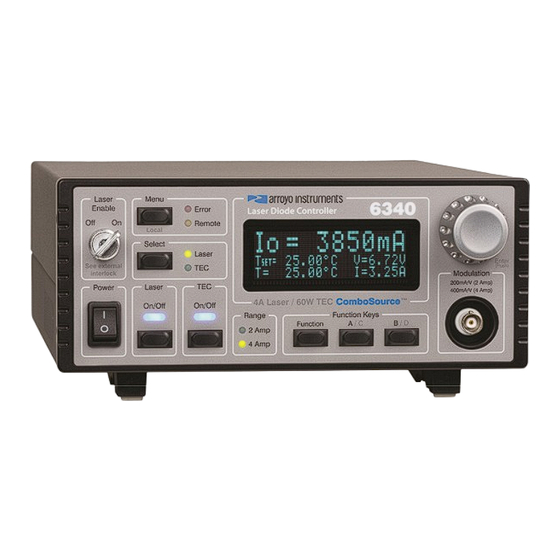
6300 Series ComboSource User’s Manual · Page 11 Operation The Front Panel Operation of the ComboSource is very straightforward. The sections below will help familiarize you with the front panel, the display, and the menu structure. 6300 ComboSource Main Screen The front panel is designed for ease of operation. - Page 12 Page 12 · 6300 Series ComboSource User’s Manual button, primary used when making changes in the menu, but can also be used to change the view mode in the main display (see Main Display Screen below). There are eight LEDs: two blue LEDs to indicate the on/off state of the laser or TEC;...
- Page 13 6300 Series ComboSource User’s Manual · Page 13 Example displays are shown below: 3850.1mA .LoBW. SET= Im=950.1µA Vf=1.941V 25.00°C V= 6.72V SET= 25.00°C I= 3.25A Main Display: Both Small Io= 3850.1 25.00°C V= 6.72V SET= 25.00°C I= 3.25A Main Display: Laser Large 3850.1mA .LoBW.
- Page 14 Page 14 · 6300 Series ComboSource User’s Manual Mode Setpoint Displayed Measurements Laser Current (mA) PD current or power and voltage PD current (μA) Current and voltage PD power (mW) Current and voltage Voltage (V) Current and PD current or power Temperature (°C) Temperature, current and voltage Sensor (kΩ, mV, uA, or Ω)
-
Page 15: Settings And Menus
6300 Series ComboSource User’s Manual · Page 15 Settings and Menus All parameters of the ComboSource can be viewed and changed within the menu. The menus are constructed with the most used parameters first, and grouped by section. To change any setting, press Menu to enter the menu then rotate the knob to select the submenu. - Page 16 Page 16 · 6300 Series ComboSource User’s Manual Menu Description Factory Default Vf Limit This setting controls the maximum amount of Maximum forward current that can be delivered to the laser diode. This limit is implemented in hardware for high speed response. For more information about limits, see see Hardware and Software Limits below.
- Page 17 6300 Series ComboSource User’s Manual · Page 17 Menu Description Factory Default On Delay The delay, from the time the Output button is 3000ms pressed to when the output is actually energized. Laser Menu » Advanced Off if TEC Turns off the laser output if the TEC turns off Off if TEC Turns off the laser output if the TEC exceeds the temperature limit...
- Page 18 Page 18 · 6300 Series ComboSource User’s Manual Menu Description Factory Default Gain Gain controls the response of the temperature controller. A higher gain value will cause the controller to respond more quickly to the difference between the set point and the actual temperature, while a lower value will cause it to respond more slowly.
- Page 19 6300 Series ComboSource User’s Manual · Page 19 Menu Description Factory Default Tol Time Tolerance time is the amount of time, in seconds, 5 seconds that the actual temperature must be within the set point temperature +/- the Tol Temp value for the unit to be considered in tolerance.
- Page 20 Page 20 · 6300 Series ComboSource User’s Manual Menu Description Factory Default RTD C The C term in the RTD equation. 4.00000E-12 RTD R The R term (in Ω) in the RTD equation. 100.00 AD590 M The slope term in the AD590 correction 1.00000 equation.
- Page 21 6300 Series ComboSource User’s Manual · Page 21 Menu Description Factory Default TEC Menu » Advanced » User Cal Edit Cal Must be set to ‘Yes’ before user calibration settings can be changed. Reset Cal Reset the TEC user calibration data to factory defaults (all slopes to 1, all offsets to 0).
-
Page 22: Saving And Restoring Configurations
Page 22 · 6300 Series ComboSource User’s Manual Menu Description Factory Default Display Display mode, which is used to control the layout Normal on the main screen. Normal will display more information in a smaller font, while Large will display the actual values only in a larger font. When changing the set point, the set point will be displayed during the set point change. -
Page 23: Using The Function Keys
6300 Series ComboSource User’s Manual · Page 23 configurations are not erased, and user calibration data is not cleared. To erase user calibration data, you must use the Reset Cal menu item found in the Laser and TEC User Cal menus, or manually adjust each user calibration entry to 1 (for slope) or 0 (for offset). - Page 24 Page 24 · 6300 Series ComboSource User’s Manual Scripts are a bit more difficult, as you need to create them using the computer interface. See the Computer Interfacing Manual for more information on how to construct and store scripts. Once your configurations and scripts have been created, go to Main Menu » Func Key Menu »...
-
Page 25: Connecting To The Combosource
Poor or intermittent connections can damage or destroy the laser diode. A cable is required for both the TEC and Laser outputs. Arroyo Instruments carries cables specifically designed for these applications, both with a DB connector on the device end or with a bare wire pigtail for terminating the... -
Page 26: Power And Cable Connections
Page 26 · 6300 Series ComboSource User’s Manual NOTE Connections to the ComboSource and the fixture must be secure. Tighten any screws on the DB connectors, and make sure all connections are in good condition. See the manual of your laser (and fixture) for additional safety and operational information. - Page 27 6300 Series ComboSource User’s Manual · Page 27 Arroyo Instruments has followed industry conventions for laser DB-9 connections, and is compatible with pin-outs from other vendors, such as ILX and Newport. However, care should still be taken when interfacing the ComboSource to other vendors’...
-
Page 28: Grounding Considerations
Page 28 · 6300 Series ComboSource User’s Manual RS232 Connector The RS232 connection is male DB-9 connector wired in a NULL modem configuration. Description Receive Transmit Ground 1,4,6 Commoned together Commoned together No connection Shell Earth ground RS232 Connector (DB-9 Male) For more information on using the RS232 interface, see the Computer Interfacing Manual which is included on the CD that accompanied this product. -
Page 29: Installing The Usb Drivers
Manager appears, click on the plus sign to the left of Ports. The port identified as a USB Serial Port is the ComboSource. In the event you have multiple Arroyo Instruments products plugged in simultaneously, you will need to experiment to see which instrument was assigned to which port. For example, you could send a *IDN? query and see which instrument goes into remote mode. - Page 30 Page 30 · 6300 Series ComboSource User’s Manual just above the highest voltage needed for the maximum set point you will be using. This gives the unit a “hint” as to the required voltage, and may be enough to eliminate the thermal trip error. If your instrument still continues to thermally trip, you can add a series resistor (to the laser or TEC, as appropriate) to remove some of the power from inside the unit.
-
Page 31: Using The Laser Driver
6300 Series ComboSource User’s Manual · Page 31 The 6340-QCL ComboSource also has the following minimum voltage requirements for the laser output: Using the Laser Driver Laser Control Modes ComboSource offers the following control modes: Io (ACC), Io HiBW (ACC), Im (AMC), Po (APC), and Vf (AVC). Changing the control mode is done through the menu by changing the Mode parameter in the Laser menu to one of these values. -
Page 32: Using The Laser Limits
Page 32 · 6300 Series ComboSource User’s Manual enough forward current through the laser diode to generate the selected monitor diode current. Only low frequency modulation (10Hz or less) is possible in Im mode due to the feedback latencies of the photodiode itself. Po mode (also referred to as APC, or automatic power control, mode) is simply Im mode with a mathematical constant applied to the set point, providing a convenient way of operating in milliwatts. -
Page 33: Analog Modulation
6300 Series ComboSource User’s Manual · Page 33 Unlike the voltage limit, the current limit simply prevents the ComboSource from delivering more current than the limit is set to. When the current limit engages, the output will remain on. The intermittent contact circuit is designed to protect against faulty connections by detecting fast changes in voltages which can be caused by poor wiring or faulty connectors. -
Page 34: Compensating For Voltage Loss
Page 34 · 6300 Series ComboSource User’s Manual The 1220B or 1221B cables recommended by Arroyo Instruments are shielded twisted pair, and will provide good modulation performance. Current (A) Recommend Wire Gauge 1 or less 24 AWG 22 AWG 20 AWG Compensating for Voltage Loss All cables and connectors have a small, but measureable, resistance. - Page 35 6300 Series ComboSource User’s Manual · Page 35 However, remote voltage sense does have a few drawbacks: If the remote sense wires are disconnected, it disables the hardware voltage limit as well as the measurement of laser voltage. Requires two additional wires to be run to the device. It is the first of these two drawbacks that is of the biggest concern.
- Page 36 Page 36 · 6300 Series ComboSource User’s Manual measured voltages is the voltage loss in the cable. Use this formula to calculate resistance: Output laser Cable AMPS Note that the current is expressed in amps, not milliamps, so divide the set point by 1000 before using it in this equation.
-
Page 37: Using The Temperature Controller
ComboSource has integrated support for many of the mounts offered by Arroyo Instruments, such as the 205 TEC Butterfly LaserMount. To simplify operation when using these mounts, you can change the Mount setting in the menu to the mount type you are using. By selecting a mount, the current limit,... -
Page 38: Working With Thermistors
Page 38 · 6300 Series ComboSource User’s Manual hidden from the menu, and the current limit is adjusted to the mount’s rated limit to prevent damage to the mount’s Peltier cooler. Adjusting the Mount setting to User Defined removes all software limits, allowing unrestricted operation of the ComboSource. -
Page 39: Working With Rtds
6300 Series ComboSource User’s Manual · Page 39 application temperature, which varies greatly by temperature and thermistor types. ComboSource supports operation using a 10μA or 100μA constant current source, which limits the upper control range to 450kΩ or 45kΩ, respectively. To minimize noise and maximize stability, you should select highest current while still allowing you full operation across your required temperature range. - Page 40 Page 40 · 6300 Series ComboSource User’s Manual using the Callendar-van Dusen method. By default, the ComboSource uses the Laboratory standard coefficients, which are for a 0.003926Ω/ Ω/°C curve (A = 3.9848x10 , B = -0.58700x10 , C = 4.0000x10 , and R = 100).
-
Page 41: Working With Ad590S And Lm335S
6300 Series ComboSource User’s Manual · Page 41 Working With AD590s and LM335s Unlike thermistors and RTDs, an AD590 or LM335 is considered an “IC” sensor because it has an active transistor element that responds to changes in temperature by producing a current (AD590) or voltage (LM335). Also unlike thermistors and RTDs, these IC sensors produce a linear response, making conversion to temperature a very straightforward calculation. -
Page 42: Resistive Heaters And Heat/Cool Only Modes
Page 42 · 6300 Series ComboSource User’s Manual Auto Fan is turned on whenever the TEC output is on, and turns off when the TEC output is turned off. Fan is always on. Delay Similar to the Auto mode, the fan is turned on whenever the TEC output is on, but when the TEC is turned off, the fan will remaining running for an addition number of minutes as defined by the Ext Fan Off setting. -
Page 43: Using The Autotune Function
6300 Series ComboSource User’s Manual · Page 43 Where is the error in the system, expressed as: = Target - Actual The controller can calculate ideal PID values using the AutoTune function, discussed in detail in the next section. To manually adjust the PID, start by changing the I and D values to zero, and adjust the P value so that it reaches the set point as quickly as possible without overshooting the set point an unacceptable amount. - Page 44 Page 44 · 6300 Series ComboSource User’s Manual The instrument displays the AutoTune test point. Use the knob to adjust the test point to your typical operating point. If you will be operating at two or more set points, you will usually want to select the set point furthest away from ambient. Once the temperature test point is selected, press ENTER.
-
Page 45: Using The Autotune Function Remotely
6300 Series ComboSource User’s Manual · Page 45 If the AutoTune process fails, the instrument will display an E-436 AutoTune Failed error message and turn the output off. Any of the following can cause the AutoTune to fail: Noisy temperature measurements, which make it difficult to accurately measure oscillations ... -
Page 46: Compensating For Tec Cable Resistance
Page 46 · 6300 Series ComboSource User’s Manual Compensating for TEC Cable Resistance Because the high currents the ComboSource can drive through the Peltier, the voltage loss through the cable and connectors of the system can significantly affect the TEC voltage measurement. In most cases, accurate voltage measurements are not needed, and the default compensation of the instrument is sufficient. -
Page 47: Field Calibration (User Cal)
6300 Series ComboSource User’s Manual · Page 47 Field Calibration (User Cal) ComboSource is typically calibrated annually, and calibration can be done one of two ways: the instrument can be returned to the factory for a full recalibration, or the User Cal menu can be used for simpler slope/offset calibration. - Page 48 Page 48 · 6300 Series ComboSource User’s Manual Laser User Calibration Entries Menu Entry Description I Set LoM Io set point, low range, slope I Set LoB Io set point, low range, offset (mA) I Set HiM Io set point, high range, slope I Set HiB Io set point, high range, offset (mA) Im Set M...
- Page 49 6300 Series ComboSource User’s Manual · Page 49 The short form for Slope is typically ‘m’, and the short form for offset is typically ‘b’, which is why you see these letters used in the instrument menu (you will often see a similar version of the equation above written as y=mx+b). Depending on how you wish to calibrate, a simple offset calibration may be sufficient, where only the offset value is adjusted and the slope is left at 1.
- Page 50 Page 50 · 6300 Series ComboSource User’s Manual As stated above, correction is done using a linear equation, and we need to calculate the slope and offset. Slope must be calculated first, and is calculated using the following formula: Slope = (y –...
- Page 51 6300 Series ComboSource User’s Manual · Page 51 instrument. For example, if you want to calibrate the laser current to within 0.1mA, then your meter would have an accuracy of 0.025mA or better. Using lower accuracy meters could actually degrade the accuracy of the instrument rather than improving it.
-
Page 52: Specifications
Page 52 · 6300 Series ComboSource User’s Manual Specifications Description Laser Specifications 6301 6305 6310 6340 LASER SETPOINT High High High High LASER CURRENT Range Range Range Range Range Range Range Range Range (mA) 1000 2000 4000 Max Resolution (mA) 0.002 0.005 0.01... - Page 53 6300 Series ComboSource User’s Manual · Page 53 Description Laser Specifications 6310-QCL 6340-QCL LASER SETPOINT High High LASER CURRENT Range Range Range Range Range (mA) 1000 2000 4000 Max Resolution (mA) 0.02 0.05 Accuracy (±[% set+mA]) 0.025% 0.025% 0.025% 0.05% + 0.12 + 0.3 + 0.5...
- Page 54 Page 54 · 6300 Series ComboSource User’s Manual Description TEC & General Specifications SETPOINT TEMPERATURE Range (ºC) -99 to 250 Resolution (ºC) 0.01 Therm Accuracy (± ºC) 0.05 AD560 Accuracy (± ºC) 0.05 LM335 Accuracy (± ºC) 0.05 RTD Accuracy (± ºC) 0.05 Stability (1hr) (±...
-
Page 55: Error Messages
6300 Series ComboSource User’s Manual · Page 55 Description TEC & General Specifications 0.03 + 0.1 Accuracy ( [% read+Ω]) ± LIMITS CURRENT Resolution (mA) Accuracy (mA) GENERAL Display Type 2x20 VFD Laser Connector DB-9, female TEC Connector DB-15, female Fan Supply 4 –... - Page 56 Page 56 · 6300 Series ComboSource User’s Manual E-410 Temperature was out The temperature went out of tolerance and the of tolerance, output output was turned off. turned off E-415 Sensor short, output A sensor short circuit was detected and the turned off output was turned off.
- Page 57 6300 Series ComboSource User’s Manual · Page 57 disabled output forced a shutdown of the laser output. E-512 Power failure A power failure was detected. E-514 Laser mode change A change in the operating mode of the disabled output ComboSource while the output was on shutdown the output.
-
Page 58: Maintenance And Service
Arroyo Instruments. A complete list of distributors is available on the Arroyo Instruments web site. You can contact Arroyo Instruments through one of these methods:... - Page 59 ComboSource User’s Manual · Page 59 European Community Declaration of Conformity EC Declaration of Conformity I/We Arroyo Instruments 1201 Prospect Street San Luis Obispo, CA declare that 6300 Series ComboSource Laser Diode Controller In accordance with the following directives EMC Directive: 89/336/EEC...
- Page 60 Page 60 · 6300 Series ComboSource User’s Manual Copyright © 2019, Arroyo Instruments. All Rights Reserved P/N 530-1029F...
Need help?
Do you have a question about the ComboSource 6300 Series and is the answer not in the manual?
Questions and answers