Advertisement
Serge Slopes (DTG)
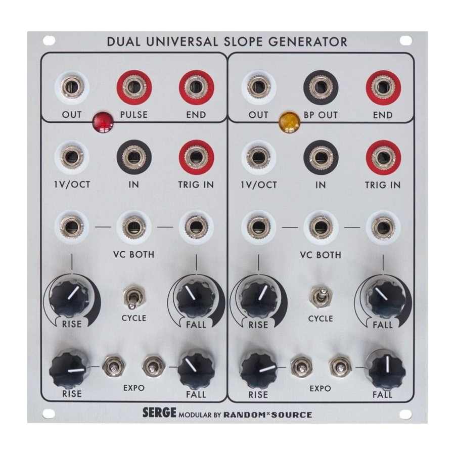
SERGE Slopes (DTG)
2" DSG
Patch the red (GATE) out into TRIG IN on either side for cycle mode - of course the left side can also
achieve this with the switch. Both rise and fall can be manually set to create anything from a sawtooth
wave to triangle to a reverse sawtooth (or anything in between). By using the lower switch, a control
voltage can be set to affect RISE, FALL or BOTH slopes. Both sides feature (black) audio INs for filter-
ing effects etc.
The 4U pcb kit consists of a panel pcb serving as an interface to the front panel as well as a main pcb
which
already contains most of the parts in surface-mount technology (SMT).
mk2
RANDOMSOURCE.NET
RANDOM*SOURCE
Slopes is a 2" wide version of the Dual
Universal Slope Generator mk2 that is
designed to cover both oscillator / audio as
well as clock generator and envelope duties.
All Random*Source Serge modules are
brought to you under license and in coop-
eration with Serge Tcherepnin.
The power of the DSG mk2
This 2" version of the Dual Universal Slopes
Generator features a cycle switch and an
1V/Octave input for the left side for easy
use as an oscillator (that tracks over a bass
range of up to 4 octaves or more). Best
tracking is achieved with the Rise set to
max and Fall controlling the pitch. The right
side is essentially identical except for those
extras.
Outputs are the normal (unipolar / DC)
output (white) and a gate output underneath
the pulse width of which depends on the
ratio of the rise and fall of the normal output.
1
Advertisement
Table of Contents

Summary of Contents for Random*Source SERGE DSG mk2
- Page 1 Universal Slope Generator mk2 that is designed to cover both oscillator / audio as well as clock generator and envelope duties. All Random*Source Serge modules are brought to you under license and in coop- eration with Serge Tcherepnin. The power of the DSG mk2 This 2”...
- Page 2 RANDOM*SOURCE Serge Slopes (DTG) Please note: The main DSG pcb is the same as used for other incarnations of the DSG mk2 - whether the • DSG pcb is a “contemporary version” or a “classic” version does not matter. However, both...
- Page 3 RANDOM*SOURCE Serge Slopes (DTG) Bill of Materials Trimmers 2 100k DSG: Offset Trimpot (Bourns 3362P, Vishay T73YP104KT20 or similar) DSG: to adjust the uni-polar output to a range of 0V to 5V 2 5k DSG: 1V/Oct Trimpot (Bourns 3362P, Vishay T73YP502KT20 or anything that matches the footprint) to adjust the tracking of the 1V/Oct input.
- Page 4 RANDOM*SOURCE Serge Slopes (DTG) DSG mk2 Configuration The DSG mk2 might be pre-configured to be used in a (full) DSG with separate control over Rise and Fall. This is perfect for use in a 3” wide DSG, however, to use the pcb in a 2” version, you (may) have to change this setting: SEParate control of Rise / Fall: two 0R resistors (SEP) act as links / jumpers and COM is open.
- Page 5 RANDOM*SOURCE Serge Slopes (DTG) Mount the pots onto the component pcb. Pots should sit on the side marked on the pcb - this side faces the front panel. Don‘t solder them in yet. Stick the LEDs into the component pcb - the long leg must be at the + side. Carefully mount component pcb (with the pots and LEDs inserted) onto the front panel. First slide / push the LEDs into the LED lens - all the way, this may take a bit of force. You may then have to wiggle each pot a bit to get the pots through. Make sure the threads of the pots go through com- pletely and the pots sit right at the front panel. Screw the pots to the panel to make sure of that. Once everything is nicely in place, especially the LEDs sitting inside (and not on top) of the LED lenses, solder the LEDs and the pots onto the component pcb (while the front panel is attached). Solder the switches in by soldering the air-wires onto the correcponding contacts: 10. Solder the banana jacks in. You can either solder them directly to the surrounding vias (rings around) or - which makes removing easier should you ever need to do that - by inserting a stiff (bare) wire into the little hole (via) and solder that wire to the top of the banana jack: 11. Solder the through-hole parts onto the main board. 12. Attach any screws / spacers if desired and mount the main pcb onto the component pcb. 13. Connect a power cord supplying +12V, GND, GND, -12V to the MTA-header on the main board and you should be ready to go :-) RANDOMSOURCE.NET...
- Page 6 (up to 440Hz). Power Consumption DSG mk2: ≈ 85mA @ +12V and ≈ 65mA @ -12V (Version 25. September 2017, 9:36 PM) SERGE Modular by Random*Source. Module and circuit under license from Serge Tcherepnin. All rights reserved. RANDOMSOURCE.NET...
Need help?
Do you have a question about the SERGE DSG mk2 and is the answer not in the manual?
Questions and answers