Table of Contents
Advertisement
Advertisement
Table of Contents

Related Manuals for AxleTech PSS165

Summary of Contents for AxleTech PSS165
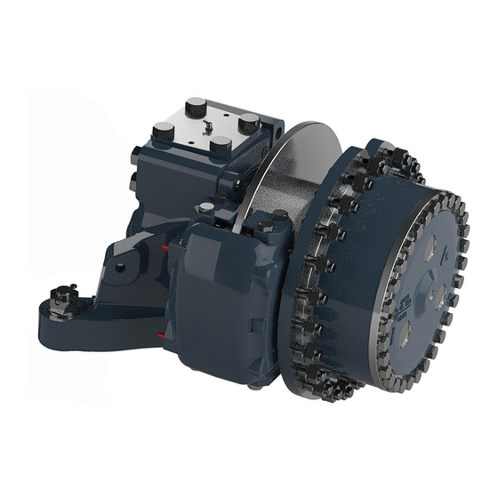
- Page 1 SERVICE MANUAL ASM-0910E October 2019 Planetary Steer Axle Knuckle Designs PSS165 PSC353 PSC825 PSC1614 PSC1875 PSS166 PSC594 PSC826 PSC1615 PSC1876 PSC204 PSC822 PSC1044 PSC1617 PSC4564 PSC205 PSC824 PSC1045 PSC1764 PSC4565 PSOC205 PSTC824 PSC1485 PSC1794 PSC5494...
-
Page 2: Table Of Contents
Table of Contents Table of Contents Disassembly ............ 9 Service Notes ...........ii Steering Universal Joint ........9 Asbestos and Non-Asbestos Fibers Warning ..iii Wing Bearing Yokes ..........9 Service Precautions .......... v Round Bearing Yokes or Cardan Joint ..... 10 Towing ............. v Constant Velocity Joint ........ -
Page 3: Service Notes
AxleTech shall have no liability of any kind for damages arising out of (or in connection with) any other use of the information contained in this manual. -
Page 4: Asbestos And Non-Asbestos Fibers Warning
Asbestos and Non-Asbestos Fibers Warning Asbestos and Non-Asbestos Fibers Warning OSHA Toxic and Hazardous Substances 29 CFR 1910.1001 Work practices and engineering controls for automotive brake and clutch inspection, disassembly, repair and assembly -- Mandatory This mandatory appendix specifi es engineering controls (4) A HEPA-fi... - Page 5 Asbestos and Non-Asbestos Fibers Warning (5) The brake support plate, brake shoes and brake com- [D] Wet Method ponents used to attach the brake shoes shall be thor- (1) A spray bottle, hose nozzle, or other implement capa- oughly washed before removing the old shoes. ble of delivering a fi...
-
Page 6: Service Precautions
INJURY OR DEATH. REFER TO THE VEHICLE Due to the wide range of environments and applications MANUFACTURER FOR PROPER JACKING AND for AxleTech axles, it is recommended to follow the towing SUPPORT METHODS. instructions from the vehicle Original Equipment Manufac-... -
Page 7: Repair Warnings
• A stronger tightening torque may lead to yielding of • Always use genuine AxleTech replacement parts. the bolt or an increasing risk of cracking. -
Page 8: Repair Welding
Please contact AxleTech if you believe that repair welding will work for your particular situation. Omissions Every eff ort has been made to ensure the accuracy of all information in this manual. -
Page 9: General Assembly Instructions
General Assembly Instructions General Assembly Instructions During disassembly: • Remove bearings with pullers designed for this Tapered Roller Bearings purpose to avoid damaging the bearing. • Carefully wash and re-lubricate all bearings as CAUTION removed and protectively wrap until ready for use. •... -
Page 10: Seals
General Assembly Instructions Seals During assembly: • Verify the seal bearing surface edges are free of burrs WARNING and nicks that may damage seals. • Lubricate properly: WHEN APPLYING SOME SILICONE GASKET MATERIALS, • Lubricate the entire interior surface of the ring SMALL AMOUNTS OF ACID VAPOR ARE PRESENT. -
Page 11: Fasteners
• Clean excess material off all surfaces as thoroughly as a special tool to split the taper and separate the com- possible. ponents. AxleTech Service recommends that ball joint tapered joints housed within steel or ductile iron com- • Clean and carefully degrease surfaces (any lubricant ponents can be split using a “shock method”. -
Page 12: Introduction
When replacing parts, only use factory original parts and parts sets. Parts must be ordered from AxleTech International. Any damage to parts not described in this manual must be repaired or replaced using original parts. -
Page 13: Axle Designs Covered In This Manual
Introduction Axle Designs Covered in This Manual Identifi cation Tag The following knuckle and king pin designs are covered in All products are identifi ed by the model and serial num- this manual. ber. This information is stamped on the identifi cation tag and affi... -
Page 14: Exploded Views
Introduction Exploded Views ALTERNATE STEERING ARM Item Description Item Description King Pin Bushing Steer Knuckle Upper King Pin Cap Steer Knuckle Stop Screw Upper King Pin Cap with Integral Steer Arm Steer Knuckle Stop Screw Lock Nut Upper King Pin Cap Capscrew (Long) Lower King Pin Cap Thrust Washer or Grease Seal Upper King Pin Cap Capscrew (Short) Lower King Pin Cap Shims... - Page 15 Introduction NON-SEALED KING PIN DESIGN SHOWN Item Description Item Description Upper King Pin Cap Lower King Pin Cap Thrust Washer or Grease Seal Upper King Pin Cap Capscrew (Long) Lower King Pin Cap Shims Upper King Pin Cap Capscrew (Short) Lower King Pin Cap Upper King Pin Cap Grease Fitting Lower King Pin Cap Capscrew...
-
Page 16: Removal And Disassembly
Removal and Disassembly Removal and Disassembly Steer Knuckle Removal 1. Remove the hydraulic powering steer cylinder from the WARNING knuckle. TO PREVENT SERIOUS EYE INJURY, ALWAYS WEAR EYE 2. Remove the tie rod assembly from the knuckle. PROTECTION WHEN PERFORMING VEHICLE MAINTE- NANCE OR SERVICE. -
Page 17: Axle Shaft Assembly Removal
Removal and Disassembly 9. Remove the king pin cap thrust washer and grease • For sealed king pin bushing with seal piloted in seals. knuckle: The grease seals will remain in the knuckle bore • For non-sealed king pin bushing: when removing the king pin caps. - Page 18 Removal and Disassembly Item Description Item Description Planetary Spider Steer Knuckle Tie Rod Nut Cotter Pin Wheel Hub Steer Knuckle Tie Rod Assembly with Ball Stud Ends Upper King Pin Capscrews (4) Lower King Pin Cap Thrust Washer or Grease Seal Upper King Pin Cap Lower King Pin Cap Shims...
-
Page 19: King Pin Bushing Inspection
Removal and Disassembly King Pin Bushing Inspection 3. Use a sleeve slightly smaller than the housing bore to remove the king pin bushing by driving it TOWARD the Inspect the king pin bushings in the axle housing. outside of the trunnion. •... -
Page 20: Axle Shaft Oil Seal And Bushing
• NEVER disassemble Permalube universal joints. oil seal installation depth “X” for later reinstallation of Disassembly will void the AxleTech warranty. This style new oil seal assembly. has no grease fi tting on the center parts assembly. -
Page 21: Round Bearing Yokes Or Cardan Joint
Disassembly Round Bearing Yokes or Cardan Joint 4. Turn the vertical yoke over. Repeat Step 3 to remove the needle bearing and retainer on the opposite side. 1. Use a suitable tool to remove the snap rings from the two ears in each yoke. 5. -
Page 22: Constant Velocity Joint
Preparing Parts for Assembly Constant Velocity Joint Preparing Parts for Assembly Remove the rubber boot using the following instructions. Cleaning If the balls or raceways are worn or damaged: Replace the entire shaft and joint assembly. WARNING 1. Cut the strapping band from the outside diameter SOLVENT CLEANERS CAN BE FLAMMABLE, POISON- of the rubber boot. -
Page 23: Parts Inspection
Assembly and Installation Parts Inspection Assembly and Installation Carefully inspect all disassembled parts before assembly WARNING and replace any worn, cracked, or damaged parts. Check for cracks using dye penetrant, magnetic fl ux, or fl uores- TO PREVENT SERIOUS EYE INJURY, ALWAYS WEAR EYE cent particle testing methods. - Page 24 5. Use the vise to press the bearing cap into the yoke Constant Velocity Joint and onto the arm of the cross. The cross must move NOTE: AxleTech kit number MPS 4707 is available for the freely in both caps. PSC205 axle model. The kit contains a new boot, outer...
-
Page 25: Axle Shaft Bushing & Seal Installation
Assembly and Installation 8. Have a second person use a blunt-edged tool, such as Installation of Axle Shaft Bushing & Seal a fl at-blade screwdriver, to depress the lock ring into 1. Use an appropriate driver to install a new axle shaft the groove while pushing the long shaft partially into bushing in the axle housing. -
Page 26: Installation Of King Pin Bushings
Assembly and Installation Installation of King Pin Bushings CAUTION NEVER APPLY EXCESSIVE FORCE WHEN INSTALLING Non-Sealed King Pin Bushings THE SEAL THAT BOTTOMS ON THE BORE SHOULDER. 1. Verify the housing bore is clean. Use an emery cloth to EXCESSIVE FORCE CAN DAMAGE THE SEAL AND LEAK- remove burrs. - Page 27 Assembly and Installation Sealed King Pin Bushings NOTES: • Kit MPS 4470 has KP bushings, KP caps, grease seals, WARNING grease fi ttings, and shims for two wheel ends of the PSC1485 axle. TAKE CARE USING LOCTITE ADHESIVE TO AVOID SE- •...
-
Page 28: Assembly Of Steer Knuckle
Assembly and Installation Assembly of Steer Knuckle 1. Use AxleTech specifi cation number O-617-A or O-617-B grease to lubricate the king pin bushing bores. For fl anged bushings, also lubricate the thrust WARNING faces. TO AVOID SERIOUS PERSONAL INJURY AND POSSIBLE 2. -
Page 29: Steer Knuckle Adjustment
2. Use a feeler gauge to measure the gap. 1. Install the original shim pack on the cap. 2. Apply a liberal coating of AxleTech specifi cation For fl anged-type sealed king pin bushings: number O-617-A or O-617-B grease into the grooved Measure between the upper king pin cap shoulder face of the thrust washer. -
Page 30: Adjust Knuckle Vertical End Play
Assembly and Installation Dial Indicator Method Adjust Knuckle Vertical End Play 1. Attach a dial indicator to a fi nished surface on the 1. Remove the upper and lower king pin caps. Remove knuckle to record the knuckle vertical movement the shim packs and measure the total shim pack relative to the axle housing. -
Page 31: Final King Pin Cap Installation
Assembly and Installation Final King Pin Cap Installation Non-Sealed King Pin 1. Install the new shim pack on the upper king pin cap. Sealed King Pin 2. Install the upper king pin cap into the knuckle. Use the 1. Install the grease seal. mounting capscrews to drive the cap into the knuckle. -
Page 32: Axle Components
• ESM-0095 - Planetary Axle Wheel Ends: Covered Planetary Spider Design Service Manual 1. Apply AxleTech specifi cation number O-617-A or O-617-B grease to the oil seal lip and bushing in the • ESM-0100 - Planetary Axle Wheel Ends: Coverless axle housing. -
Page 33: Torque Specifi Cations
Torque Specifi cations Torque Specifi cations Torque Item Fastener Location Size lbs. ft. N·m 9/16"-12 130-165 176-224 King Pin Cap Capscrew 3/4"-10 310-400 420-542 7/8"-14 575-750 780-1017 PSOC205 Only: 1"-12 850-1100 1152-1491 Apply Adhesive STF 02-462 M14x2.0 150-170 203.4-230.5 5/8"-18 60-115 81-156 7/8"-14... -
Page 34: Lubrication Specifi Cations
Lubrication Specifi cations Lubrication Specifi cations Typical Axle Housing Oil Capacities for Planetary Steer Axle Models* Axle Housing Lube Capacity (estimated) Axle Model Pints Liters PSS165 PSS166 PSC204 13.7 PSC205 13.7 PSOC205 13.7 PSC353 11.8 PSC594 13.2 PSC822 PSC824 14.2 PSTC824 14.2... -
Page 35: Appendix
Appendix Appendix Torque Specifi cations... - Page 36 Appendix...
-
Page 37: Torque Values For Fasteners
Appendix Torque Values for Fasteners Measuring Metric Fasteners 1. The torque values in the previous tables are for fasteners with a light application of oil on the threads. 2. If the fasteners are dry, increase the torque values by ten percent (10%). 3. - Page 38 © 2018 AxleTech International LLC. All rights reserved. AxleTech and AxleTech International are registered trademarks of AxleTech International LLC. All other brands and product names are trademarks or registered trademarks of their respective owners. Information supplied by AxleTech is believed ASM-0910E 10/19 to be accurate and reliable.
Need help?
Do you have a question about the PSS165 and is the answer not in the manual?
Questions and answers
Hi, I Required Axle Tech 4000 Series Steerable rigid Axle Service Manual and Maintenance Manual.