Table of Contents
Advertisement
Quick Links
Advertisement
Table of Contents

Summary of Contents for IST ATEX HR 600
- Page 1 SOLVENT RECLAIMER ATEX HR 600 USE AND MAINTENANCE GUIDE...
- Page 3 CAUTION OPERATORS AND SERVICE TECHNICIANS SHALL READ THIS HANDBOOK THOROUGHLY BEFORE STARTING TO USE THE MACHINE OR CARRYING OUT MAINTENANCE. THIS HANDBO- OK MUST BE KEPT NEAR THE MACHINE SO THAT IT MAY BE READILY CONSULTED AND MUST ALWAYS ACCOMPANY THE MACHINE EVEN IF SOLD ON AT A LATER DATE.
-
Page 4: Table Of Contents
CONTENTS CAUTION This use and maintenance guide is to be considered as a part of the system itself. Read the notes and instructions it contains carefully, as they supply important information concerning safe operation and maintenance. Keep the guide in a safe place for further reference. 1 INTRODUCTION ........................ - Page 5 CONTENTS 4.7 HYDRAULIC CONNECTION ................... 33 4.7.1 NITROCELLULOSE KIT (optional) ................34 4.8 DEMISTER KIT (optional) ....................34 4.9 ELECTRIC CONNECTION ....................35 4.10 FILLING LIQUID RING VACUUM AND VERIFY ROTATION DIRECTION ....36 5 OPERATING INSTRUCTIONS ................... 37 5.1 CONTROLS........................37 5.1.1 EXTERNAL CONTROL PANEL .................
- Page 6 CONTENTS 6.4 TEFLON BLADE REPLACEMENT ................... 90 6.5 DEMISTER MAINTENANCE (optional) ................91 6.6 WATER CONDENSER ..................... 91 6.7 TANK LID SEAL ........................ 91 6.8 SAFETY VALVE........................ 91 7 ALARMS - TROUBLE SHOOTING ..................93 7.1 ALARM MESSAGES ON THE DISPLAY ................93 7.2 PROBLEMS AND SOLUTIONS ..................
-
Page 7: Introduction
Use Maintenance Manual must be communicated, by the ordered, by fax (in letterhead) to IST S.p.A. In case of staff turnover for the IST RECLAIMER, the customer has to send always by fax (in letterhead) the names of the formed operators about the Use and Maintenances Manual. -
Page 8: How To Read And Use The Guide
UNDERSTANDING BY THE OPERATORS OF THE USER MANUAL AND MSDS OF THE SOLVENTS THAT ARE TO BE RECLAIMED. The assumption of the IST RECLAIMER by the customer means that they must comply with the above exposed. 1.2 HOW TO READ AND USE THE GUIDE The guide is divided into sections, chapters and paragraphs, so that information is structured in the clearest possible manner. -
Page 9: Symbols Used In The Guide
INTRODUCTION 1.4 SYMBOLS USED IN THE GUIDE Indicates situations or problems that can jeopar- DANGER dise the users’ safety due to risk of industrial accidents or death. Indicates situations or problems concerning the CAUTION system’s effi ciency of operation, which do not jeopardise the users’... -
Page 10: Conditions For Warranty Validity - Responsibility
INTRODUCTION 1.6 CONDITIONS FOR WARRANTY VALIDITY - LIABILITY I.S.T. S.p.A. warrants that the products supplied are as established in the agreement in terms of quality and type and that they are free of defects which may cause them to be unsuitable for their specifi... -
Page 11: General Information 2
GENERAL INFORMATION 2 2.1 DETAILS ABOUT THE SYSTEM AND THE MANUFACTURER Manufacturer: I.S.T. - ITALIA SISTEMI TECNOLOGICI S.p.A. via S. Anna, 590 41122 MODENA (MO) - ITALIA Phone +39.059.314305 - Fax +39.059.315726 V.A.T. Number: 02799130360 Equipment: SOLVENT RECLAIMER type: HR model: 600 2.2 IDENTIFICATION PLATE The identifi... -
Page 12: Pictographs On The System
GENERAL INFORMATION 2 2.3 PICTOGRAPHS ON THE SYSTEM Prohibition, necessity and danger pictographs are present on the system. Follow the instructions carefully, as non-observance may cause serious personal injury. Make sure that the pictographs are always present and legible, if not apply or replace them. DANGER OF ELECTROCUTION Presence of electrically powered components. - Page 13 GENERAL INFORMATION 2 GLOVES MUST BE USED FOR PROTECTING THE HANDS. A MASK MUST BE USED TO PREVENT INHALING TO- XIC SUBSTANCES. GOGGLES OR SHIELDS MUST BE USED TO PRO- TECT THE EYES AND FACE. OBLIGATION TO USE SECURITY SHOES TO PROTECT THE FEET.
-
Page 14: Safety Instructions
GENERAL INFORMATION 2 2.4 SAFETY INSTRUCTIONS Non-observance of the most elementary care and safety precautions is almost always the main cause of industrial injuries. - Read this Guide carefully before starting up, operating and carrying out maintenance opera- tions on the system; - Use the machine within the established limits defi... -
Page 15: Dangerous Chemical Reactions
GENERAL INFORMATION 2 2.5 DANGEROUS CHEMICAL REACTIONS The operator must have suffi cient knowledge of the solvent‘s characte- ristics and reactions, the dangers it can provoke and the precautions to be taken. This information is contained in the technical and safety data sheet which must be supplied together with the solvent. -
Page 16: Nitric Substances And Nitrates
GENERAL INFORMATION 2 2.5.2 NITRIC SUBSTANCES AND NITRATES It is forbidden to use the system with substances and solvents which may cause reactions due to the heating of nitric substances (Nitromethane, Aromatic nitrates) and nitrates (Nitric Acid Ester) as there is risk of explosion. 2.5.3 NITROCELLULOSE Special care must be exercised in the case of solvents contaminated with Nitro- cellulose as a residual component, as in some types of ink or paint. -
Page 17: Precautions Against Electrostatic Charges
GENERAL INFORMATION 2 2.5.5 PRECAUTIONS AGAINST ELECTROSTATIC CHARGES - The operator must not use clothing which could provoke electrostatic charges (for example, clothes made of synthetic fi bres). - Clean the tank and other parts of the system using a slightly damp cloth (not made of synthetic fi... -
Page 18: Common Reclaiming Solvents List
GENERAL INFORMATION 2 2.5.7 COMMON RECLAIMING SOLVENTS LIST (TECHNICAL REGULATION CEI EN 500 14: 1998-06) Subdivision A 1. HYDROCARBONS - Alkanes: E.g.: hexane, cyclohexane, etc. - Alkenes: E.g.: propene (propylene). Aromatic hydrocarbons: E.g.: styrene, etc. - benzenoids: E.g.: toluene, xylene, etc. - Mixed hydrocarbons: E.g.: cleaning solvent, kerosene, etc. -
Page 19: System Description 3
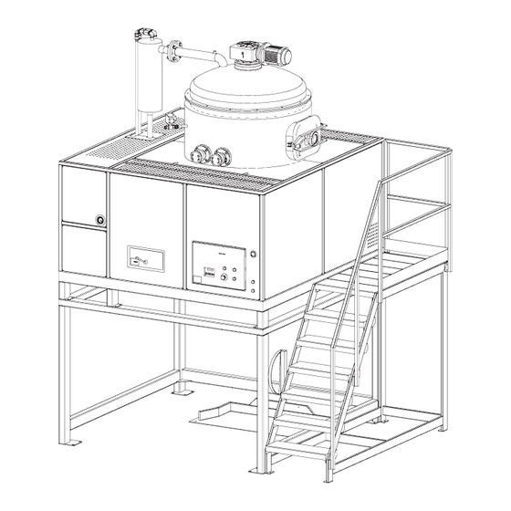
SYSTEM DESCRIPTION 3 3.1 GENERAL DESCRIPTION 6 - TANK WITH SCRAPER 1 - CONTROL BOARD 7 - WATER COOLED CONDENSER 2 - GENERAL SWITCH 8 - HIGH SPEED RECIRCULATING 3 - SCRAPPER MOTOR PUMP 4 - GAUGE VACUUM INDICATOR 9 - HEAT EXCHANGER 5 - BODY BASE SUPPORT 10 - LIQUID RING VACUUM... - Page 20 SYSTEM DESCRIPTION 3 11 - RESIDUAL COLLECTING TANK (OPTIONAL) 12 - RESIDUAL UNLOADING VALVE 13 - OIL PRESSURE VALVE...
-
Page 21: Dimensions And Overall Sizes
SYSTEM DESCRIPTION 3 3.2 DIMENSIONS AND OVERALL SIZES 2850 2300 3700 HR 600 HR 600 with Demister 2850 2300 4300... -
Page 22: Technical Data And Features
SYSTEM DESCRIPTION 3 3.3 TECHNICAL DATA AND FEATURES Reclaimer ATEX HR 600 Tank capacity 580 litres Power supply 380 - 415V/3/50 Hz +/- 2% optional: 400/3/60 Hz +/- 2% 460/3/60 Hz +/- 2% Supply voltage Low voltage 24V = Rated power Heater 44000W Oil pump 1100W Scraper 550W... -
Page 23: General Machine Description And Its Use
SYSTEM DESCRIPTION 3 3.4 GENERAL MACHINE DESCRIPTION AND ITS USE The SERIE HR Reclaimer is a machine composed by: - Solvent loading equipment through a liquid ring vacuum pump; - Solvent tank with scraper - heating system - condensation system - reclaimed solvent and polluted residual unloading The SERIE HR reclaimer has been engineered and build to reclaim some polluted solvents, after they have been used, in order to obtain the clean solvent to be re-used. -
Page 24: Emissions Of Hazardous Materials Or Substances
For any further information see part 9 and 11 of the technical manual. 3.5 EMISSIONS OF HAZARDOUS MATERIALS OR SUBSTANCES The IST Reclaimer, in its different confi gurations and versions, has been engineered and built to reclaim contaminated solvents after they have been used, in order to obtain a clean solvent ready to be re-used. -
Page 25: Improper Use Of The System
Liquid residues/muddy at temperature between 40°and 70°C (limited exposition). To give the emission value generated by the IST RECLAIMER at this stage it is not possible because they are tied to the solvent the customer is going to use and the environment where the IST RECLAIMER is installed. -
Page 27: Delivery And Set-Up 4
DELIVERY AND SET-UP 4 4.1 DELIVERY Storage temperature 0°C/ + 40°C The material is carefully checked before delivery to the shipping agents. On receiving the system, make sure that it has not been damaged during transport, that the packing has not been tampered with, and that no material has been removed. In the event of damage, or items found to be missing, inform the forwarding agent and the ma- nufacturer immediately. -
Page 28: Machine Installation
DELIVERY AND SET-UP 4 4.4 MACHINE INSTALLATION The reclaimer is assembled at customer plant by qualifi ed technicians from the construct company. The reclaimer cannot be assembled by the customer. 4.4.1 POSITION COLLECTING TANKS (optional) Position the tanks on both the reclaimer sides at about 30 cm. distance. On the right side the dirty solvent collecting tank (17) and on the left the clean solvent collecting tank (19). -
Page 29: Installing The System
DELIVERY AND SET-UP 4 4.5 INSTALLING THE SYSTEM Install the system in a spacious well-ventilated room, away from other working sta- tions and installations. The installation inside the factory involves a room classifi cation that following rule EN60079-10 is zone 2. Zone 2 extends around the reclaimer for a 1 meter fi eld. Avoid installing the reclaimer inside containers, cellars, understairs, basement, or places without natural ventilation. -
Page 30: Environmental Lighting Minimum Level
DELIVERY AND SET-UP 4 If installed outside, the system must be suitably protected against the weather conditions and secured to prevent tampering or interference by unauthorised persons. In order to ensure correct use of the system, it is advisable to leave a free space of 1000 mm on the sides 1000 mm at the rear for unloading the residues,1500 mm in front and 5000 mm in height above the fl... -
Page 31: Connection Dirty Solvent Tank
DELIVERY AND SET-UP 4 4.5.3 CONNECTION DIRTY SOLVENT TANK - HYDRAULIC CONNECTION Connect pipe (A) to junction (B). - PNEUMATIC CONNECTION Connect pipe (C) to junction (D) and pipe (E) to junction (F). - ELECTRIC CONNECTION Fix the sheath (O) to support (M). Unplug (G) from the control level (L) taking care to the fi xing screw (I). -
Page 32: Connection Clean Solvent Tank
DELIVERY AND SET-UP 4 4.5.4 CONNECTION CLEAN SOLVENT TANK - HYDRAULIC CONNECTION Connect pipe (A) to junction (B). - PNEUMATIC CONNECTION Connect pipe (C) to junction (D). - ELECTRIC CONNECTION Fix the sheath (O) to support (M). unplug (G) from the control level (L) taking care to the fi xing screw (I). -
Page 33: Pneumatic Connection
DELIVERY AND SET-UP 4 4.6 PNEUMATIC CONNECTION For the pneumatic connection insert in the rapid junction a 6-8 Rilsan pipe. The pneumatic supply should be unregu- lated. That is, the air supply from the air compres- sor should not have any pressure regulators. Caution: max. -
Page 34: Nitrocellulose Kit (Optional)
DELIVERY AND SET-UP 4 4.7.1 NITROCELLULOSE KIT (optional) Attention: be sure that your hydraulic plant which is connected to the solvent reclaimer has a minimum batch of 20 lt/min Connect the batch of your hydraulic plant to the rubber holder using a 20 mm inside diameter pipe (C), fi... -
Page 35: Electric Connection
DELIVERY AND SET-UP 4 4.9 ELECTRICAL CONNECTIONS Any operation on the electrical system, even minor ones, must be carried out by professionally qualifi ed persons. - While connecting the system, it is necessary to respect the standards defi ned by the competent Institutions and follow the accident prevention specifi... -
Page 36: Filling Liquid Ring Vacuum And Verify Rotation Direction
DELIVERY AND SET-UP 4 4.10 FILLING LIQUID RING VACUUM AND VERIFY ROTATION DIRECTION Remove the protection (D), remove the cap (A) and pour virgin solvent until it fl ows out from the connection (B). Press Reset button (7), press start button (3) and check motor (C) direction is clockwise. In case of black out or bad-functioning, always restore the solvent into the vacuum pump. -
Page 37: Operating Instructions
OPERATING INSTRUCTIONS 5 5.1 CONTROLS 5.1.1 EXTERNAL CONTROL PANEL 1 - DISPLAY 2 - EMERGENCY BUTTON. 3 - START BUTTON 4 - AIR PRESSURE GAUGE. 5 - MANUAL OPEN BUTTON – discharging valve. 6 - MANUAL CLOSE BUTTON – discharging valve. 7 - RESET BUTTON. -
Page 38: Internal Control Panel
OPERATING INSTRUCTIONS 5 5.1.2 INTERNAL CONTROL PANEL 1 - MEMORY EXPANSION (CAN BUS). 2 - TERMINAL BOARD. 3 - STABILIZED POWER SUPPLY. 4 - DIGIT TOUCH 2004 ELECTRONIC CARD. 5 - INTRINSICS BARRIERS. 6 - TRANSFORMER. 7 - FUSES. - Page 39 OPERATING INSTRUCTIONS 5 5.1.2 INTERNAL POWER PANEL 1 - HEATING ELEMENT CONTAC- 8 - VACUUM PUMP CONTACTOR. TOR. 9 - OIL PUMP CONTACTOR. 2 - HEATING ELEMENT CONTAC- TORS. 10 - SCRAPER CONTACTOR. 3 - HEATING ELEMENTS PROTEC- 11 - TERMINAL BOARD. TION.
-
Page 40: Operating And Functioning
OPERATING INSTRUCTIONS 5 5.2 OPERATING AND FUNCTIONING Before starting up the system, make sure that the contents of this Guide have been fully understood. For further clarifi cation, contact the manufacturer. The equipment can be started up only if it conforms to the protection standards defi... -
Page 41: Menu Functions Out From The Program
OPERATING INSTRUCTIONS 5 5.3.1 MENU FUNCTIONS OUT FROM THE PROGRAM - Rotate the switch (2) (chap. 3.1) illuminates the display and shows the following writing: DIGIT TOUCH 2004 DIGIT TOUCH 2004 HR RELEASE Vxxx HR RELEASE Vxxx V3.2e MODENA-ITALY PROGRAM ENTER STOP SELECTION - After a few seconds on the display shows tem-... -
Page 42: Programmed Parameters With Password
OPERATING INSTRUCTIONS 5 5.3.2 PROGRAMMED PARAMETERS WITH PASSWORD This program paragraph explains how to update some parameters which modify the solvent reclaimer functioning. Do not give this information to personnel not in charge of the machine. - Turn the main swithch (1) in 1 position keeping pressed PROGRAM until in the display appears PASSWORD PASSWORD 0000. - Page 43 OPERATING INSTRUCTIONS 5 - Re-press ENTER and in the display it will ap- pear SELEZIONE LINGUA ITALIANO (SELECT SELEZIONE LINGUA LANGUAGE) ITALIANO MODENA-ITALY PROGRAM ENTER STOP SELECTION - To modify the parameter, press ENTER, and with SELECTION select the language. SELEZIONE LINGUA ITALIANO MODENA-ITALY...
- Page 44 OPERATING INSTRUCTIONS 5 - Press SELECTION button until in the display is seen “SELECT AUTOMATIC CYCLE”. CYCLE SELECTION TIMED MODENA-ITALY PROGRAM ENTER STOP SELECTION I.S.T. solvent reclaimer enables the operator to choose the program most suitable for the solvent to be reclaimed. 1 - AUTOMATIC: this is the most versatile program, with the distillation cycle is based on solvent steam reading-out.
- Page 45 OPERATING INSTRUCTIONS 5 - Pressing many times SELECTION button, suc- cessive or previous cycle will be selected SELECTION MULTI SET POINT MODENA-ITALY PROGRAM ENTER STOP SELECTION - Once selected the chosen cycle, press ENTER and the rectangle will switch off SELECTION CYCLE AUTOMATIC MODENA-ITALY...
- Page 46 OPERATING INSTRUCTIONS 5 - Press SELECTION untill on the display appears: SCRAPER MAINTENANCE SCRAPER MAITEN. MODENA-ITALY PROGRAM ENTER STOP SELECTION ATTENTION to use this program check paragraph 5.5.5 MANUAL SCRAPER - Press SELECTION untill on the display appears: TEMP. OLIO OK AP. 050° OIL TEMP OK OPEN (OIL TEMP.
- Page 47 OPERATING INSTRUCTIONS 5 - Select the temperature, press ENTER. OIL TEMP OK OPEN 070° MODENA-ITALY PROGRAM ENTER STOP SELECTION - Press SELECTION and on the display it will appear: OK T2 TEMP. DELAY DELAY TEMPERATURE CONTROL T2 00 min MODENA-ITALY PROGRAM ENTER STOP SELECTION...
- Page 48 OPERATING INSTRUCTIONS 5 - Select the time, press ENTER. OK T2 TEMP. DELAY 60 min MODENA-ITALY PROGRAM ENTER STOP SELECTION - Press SELECTION and on the display it will appear: OK T2 TEMP. BAND REGULATION TEMPERATURE BAND T2 1° MODENA-ITALY PROGRAM ENTER STOP SELECTION...
- Page 49 OPERATING INSTRUCTIONS 5 - Select the temperature, press ENTER. OK T2 TEMP. BAND 5° MODENA-ITALY PROGRAM ENTER STOP SELECTION - Press SELECTION button and on the display the following writing appears: EXIT TEMP. T3= 45° SOLV. OUTLET TEMP T3= 45° MODENA-ITALY PROGRAM ENTER STOP...
- Page 50 OPERATING INSTRUCTIONS 5 This parameter modifi es the alarm time security of automatic loading. It has been set by I.S.T. based to the type of the loading dirty solvent system, but it may be modifi ed to improve the working time. EXAMPLE: After the START, chronometer how long it takes to fi...
- Page 51 OPERATING INSTRUCTIONS 5 This parameter inserts enable the security nitrocellulose This parameter is enabled only if the nitrocellulose option is installed in the re- claimer. - If this parameter has to be modifi ed, press ENTER, and with SELECTION select the tem- NITROCELL.ENABLE perature.
-
Page 52: Programmed Parameters
OPERATING INSTRUCTIONS 5 5.3.3 PROGRAMMED PARAMETERS Press ENTER button and the display shows: SCRAPER (only for models ROTOPLUS) This option enables the operator to choose how to use the installed scraper. MODENA-ITALY 1 - 0: scraper out of use. 2 - AUTOMATIC: scraper on automatically. 3 - PRE-CYCLE DELAY: program not activated. -
Page 53: Scraper Delay
OPERATING INSTRUCTIONS 5 5.3.4 SCRAPER DELAY (Only with option 4 Chapter 5.3.3) This option enables the operator to program the scraper delay during the cycle phase selected in the previous menu. - Press SELECTION button and the display shows SCRAPER DELAY. SCRAPER DELAY 001 min MODENA-ITALY... -
Page 54: Precycle Selection
OPERATING INSTRUCTIONS 5 5.3.5 PRECYCLE SELECTION (only available if CYCLE SELECTION = REFILL) (First phase of REFILL CYCLE) This option enables the operator to choose the working method to use during the pre-cycle phase. 1 - LOADING Nr.: the precycle time is determined from the solvent tank automatic fi lling numbers (if selected see paragraph 5.3.6). -
Page 55: Charge Nr
OPERATING INSTRUCTIONS 5 5.3.6 CHARGE Nr. (only available if CYCLE SELECTION = CHARGE Nr.) (To be used only for special products, previously discussed with IST) This program enables the operator to program the loading numbers to be done during the pre- cycle phase. -
Page 56: Pre-Cycle Duration
OPERATING INSTRUCTIONS 5 5.3.7 PRE-CYCLE DURATION (ONLY IF PRE-CYCLE SELECTION = TIMED) This program enables the operator to program how long will last each pre-cycle phase. - Press SELECTION button and the display shows PRE-CYCLE DURATION. PRE-CYCLE DURATION C=200 MODENA-ITALY PROGRAM ENTER STOP SELECTION... -
Page 57: Set Nr. Selection
OPERATING INSTRUCTIONS 5 5.3.8 SET NR. SELECTION (only if PRE-CYCLE SELECT = MULTISETPOINT) (To be used only for special products, previously discussed with IST) This program gives the operator a choice of three divided pre-cycle, different times and temperatures. - Press SELECTION button and the display shows SET NR. -
Page 58: Oil Temperature 01° Pset
OPERATING INSTRUCTIONS 5 5.3.9 OIL TEMPERATURE 01° pSET (only if SELECT PRE-CYCLE = MULTISETPOINT) This program enables the operator to program the oil heating temperature during the fi rst pre- cycle fraction. The process must be repeated for each programmed fraction. - Press SELECTION button and the display shows OIL TEMPERATURE 01°... -
Page 59: Precycle Duration 01° Pset
OPERATING INSTRUCTIONS 5 5.3.10 PRECYCLE DURATION 01° pSET (only if SELECT PRE-CYCLE = MULTISETPOINT) This program enables the operator to program how long will last the fi rst precycle fraction. The process must be repeated for each programmed fraction. - Press SELECTION button and the display shows the PRE-CYCLE DURATION 01°... -
Page 60: Time "On" Loading
OPERATING INSTRUCTIONS 5 5.3.11 TIME “ON” LOADING (Shows only if CYCLE SELECTION = REFILL chapter 5.3.2) This program enable the operator to program the valve opening time which controls the automatic dirty solvent inlet during the pre-cycle phase. - Press SELECTION button and the display shows TIME ON LOADING. -
Page 61: Time "Off" Loading
OPERATING INSTRUCTIONS 5 5.3.12 TIME “OFF” LOADING (only if CYCLE SELECTION = REFILL chapter 5.3.2) This program enables the operator to program the valve opening time which controls the automatic dirty solvent inlet during the pre-cycle phase. - Press SELECTION button and the display shows TIME OFF LOADING. -
Page 62: Refill End Cycle Selection
OPERATING INSTRUCTIONS 5 5.3.13 REFILL END CYCLE SELECTION (Second phase of REFILL CYCLE) (Shows only if CYCLE SELECTION = REFILL chapter 5.3.2) This program enables the operator tto choose the working method to use during the end-cycle phase 1 - AUTOMATIC: is the most versatile program, the reclaimer cycle is based on the solvent vapour reading. -
Page 63: Select Cycle Numbers
OPERATING INSTRUCTIONS 5 5.3.14 SELECT CYCLE NUMBERS This program enables the operator to choose the continuously distillation cycle numbers to be done. 1 - NR. OF CYCLE: is the program to select from a minimum of 1 to a maximum of 9 distillation continuous cycles. -
Page 64: Residues Unload
OPERATING INSTRUCTIONS 5 5.3.15 RESIDUES UNLOAD This program enables the operator to choose when the residual unload must be done. 0 - Makes the residual discharge after the programmed cycles are over. TIMED – make the residues discharge at the end of each distillation cycle for a max. selected time of 15 min. -
Page 65: Final Discharge
OPERATING INSTRUCTIONS 5 5.3.15.1 FINAL DISCHARGE This program allows the operator to select the last residue discharge. TIMED – make the fi nal residue discharge for a pre-selected time of 15 minutes and then closes the unloading valve. WITH SOAKING make the fi nal residue discharge for a pre-selected time of 15 min., closes the discharge valve and fi... -
Page 66: Temperatures And Times Selection
OPERATING INSTRUCTIONS 5 5.3.16 TEMPERATURES AND TIMES SELECTION. For temperatures and times settings, method proposed by I.S.T. in the next para- graph is indicative. Solvent multitude may involve different setting method. In any case contact I.S.T. company. Diathermic oil temperature must be set 30°- 40° higher than solvent boiling point (example: Acetone boiling point: 56°... - Page 67 OPERATING INSTRUCTIONS 5 - After T1 temperature setting, press ENTER button, the rectangle switches off and the tem- OIL TEMPERATURE perature is memorized. T1= 96° MODENA-ITALY PROGRAM ENTER STOP SELECTION - Press SELECTION button, on the display the following writing appears : SOLVENT TEMPE- SOLV.
- Page 68 OPERATING INSTRUCTIONS 5 - Pressing SELECTION button you can raise or lower T2 temperature setting. SOLV. VAPOUR TEMP. T2= 46° MODENA-ITALY PROGRAM ENTER STOP SELECTION - After T2 temperature setting, press ENTER button, the rectangle switches off and the tem- SOLV.
- Page 69 OPERATING INSTRUCTIONS 5 - Press ENTER button and a rectangle will fl ash in the display. CYCLE DURATION M = 120 MODENA-ITALY PROGRAM ENTER STOP SELECTION - With SELECTIONS buttons you can raise or lower CYCLE TIME SET. CYCLE DURATION M = 125 MODENA-ITALY PROGRAM ENTER...
-
Page 70: Temperatures And Times Setting For Multi Set Point Cycle Program
OPERATING INSTRUCTIONS 5 - ATTENTION when we escape from the program and it has been selected the program NR. OF T1= 23° T3= 20° CYCLES, on the display it will appera the tem- T2= 20° M= 240 C=3 perature, the time and C= (number of selected cycles ex. - Page 71 OPERATING INSTRUCTIONS 5 The number of Set to select is determined by how many mixed type of solvents with VERY different boiling point between them you have. (Example if the mixtures is made of 4 solvents with boiling points 50°- 100°- 150°- 200°...
- Page 72 OPERATING INSTRUCTIONS 5 - After Nr Set has been memorized, press two times SELECTION button, and on the display the OIL TEMPERATURE following writing appears: OIL. TEMPERATURE T1= 100° T1=100°. MODENA-ITALY PROGRAM ENTER STOP SELECTION When programming the T1 temperature (diathermic oil) in the 1st. Set it is always lowest and in the last selected Set it is always the highest.
- Page 73 OPERATING INSTRUCTIONS 5 - After T1 temperature setting press ENTER but- ton, rectangle switches off and the temperature OIL TEMPERATURE is memorized. T1= 96° MODENA-ITALY PROGRAM ENTER STOP SELECTION - Press SELECTION button, on the display the fol- lowing writing appears: CYCLE TIME MIN.120. CYCLE DURATION M = 120 MODENA-ITALY...
- Page 74 OPERATING INSTRUCTIONS 5 - Press ENTER button, on the display the rectan- gle switches off and the time is memorized. CYCLE DURATION M = 180 MODENA-ITALY PROGRAM ENTER STOP SELECTION - Press SELECTION button, on the display the following writing appears: OIL TEMP. 02^ SET OIL TEMPERATURE T1=100°...
- Page 75 OPERATING INSTRUCTIONS 5 - Press SELECTION button on the display the following writing appears: 02^SET MIN. CYCLE CYCLE DURATION TIME MIN.=120 M = 120 02^ SET Set 02^ SET cycle time basing on MODENA-ITALY solvent quantity with the highest boiling point (in this example it must be set to 60 min.) PROGRAM ENTER STOP...
-
Page 76: Cleaning Residues
OPERATING INSTRUCTIONS 5 If more than 2 Set have been selected. Press SELECTION and in the display it will appear the next Set which will be programmed in the same way of 02^SET. - To exit the program, press PROGRAM button, the led upon it will switch off. - Page 77 OPERATING INSTRUCTIONS 5 - Press PROGRAM button, the LED on this button lights and on the display “AUTOMATIC CYCLE SELECTION SELECTION” is visualized. CYCLE AUTOMATIC MODENA-ITALY PROGRAM ENTER STOP SELECTION - Press button SELECTION until the display shows the selected cycle. CYCLE SELECTION Ej.: “SELECT AUTOMATIC CYCLE”.
- Page 78 OPERATING INSTRUCTIONS 5 - With the SELECTION button go to 0113 PASSWORD 0113 MODENA-ITALY PROGRAM ENTER STOP SELECTION - Press ENTER and the rectangle will switch off and on the display it will appear: CYCLE SELECTION SELECT CYCLE SCRAPS CLEANING SCRAPS CLEANING MODENA-ITALY PROGRAM ENTER...
-
Page 79: Reclaiming Cycle
OPERATING INSTRUCTIONS 5 5.4 RECLAIMING CYCLE When the operator has made statements of Chapters 5.3, 5.4 and 5.5 pressing the button Start (3) the programmed distillation cycle begins, if the reclaimer has the option of automatic load when pressing the Start button (3), at the same time with the programmed distillation cycle, the pneumatic pump turns-on to load the dirty solvent and the pneumatic valve it opens in order to allow the dirty solvent to enter in the reclaimer tank. -
Page 80: Cycle Start
OPERATING INSTRUCTIONS 5 5.4.1 CYCLE START If the reclaimer has the LIQUID RING VACUUM PUMP or the SCRAPER, before beginning the fi rst reclaiming cycle, check the vacuum pump and scraper for correct rotation – (4.8 ELECTRIC CONNECTION) Press START BUTTON (3) , the ENTER button lights up, and the solvent steam cooling electrofan starts. -
Page 81: Unloading Residues
OPERATING INSTRUCTIONS 5 5.5 UNLOADING RESIDUES The residual unload will be done automatically but in case of a malfunction or service (see Chapter 7.1), perform the unload manually as described in Chapter 5.5.1. Do not carry out any operation when you read WAIT OK OPEN on the Display. 5.5.1 MANUAL RESIDUAL DISCHARGING At the end of the cycle open the residual unload doors, press for few second the button to open residual discharge valve (5) and wait some minutes. -
Page 82: Manual Scraper
OPERATING INSTRUCTIONS 5 5.5.3 MANUAL SCRAPER This paramenter allows to activate the scraper and not begin the distillation cycle. Enters in the program under password (see chapter 5.3.2) - Press SELECTION untill on the display appears: SCRAPER MAINTENANCE SCRAPER MAITEN. MODENA-ITALY PROGRAM ENTER STOP... - Page 83 OPERATING INSTRUCTIONS 5 - Press again the button ENTER, the led turns off and the scraper begins to rotate. SCRAPER MAITEN. MODENA-ITALY PROGRAM ENTER STOP SELECTION - Press button PROGRAM the scraper stops and automatically re-starts the programmed distilla- tion cycle MODENA-ITALY PROGRAM ENTER STOP...
-
Page 84: Checking Residues
When you have fi nished using the reclaimer, move the switch to the position “ 0 ”. 5.8 HAZARDS FROM WORKING USE Based on our experiences, the IST reclaimer, used in a NON correct form, may cause to the operator... -
Page 85: Maintenance 6
MAINTENANCE 6 6.1 SAFETY INSTRUCTIONS All maintenance operations must be carried out with the system switched OFF, after disconnecting the electric power line wall switch; (if there is no wall switch, take the plug out of the power socket). All operations on the electric system must be carried out by qualifi ed, expe- rienced personnel. -
Page 86: Replacing Diathermic Oil
MAINTENANCE 6 6.3 REPLACING DIATHERMIC OIL This procedure must be carried out by qualifi ed maintenance personnel with the machine turned off and with an oil temperature of less than 50°. After 1000 hours of activity the reclaimer blocks and on the display you read “ALARM SERVICE OIL CHANGE”. - Page 87 MAINTENANCE 6 When the machine has no more oil close the valves (B) and (C), disconnect the connection that were previously screwed to the valves and screw the caps. Connect a pump to the valve pipe (A) and position it on right corner of the residual unload zone. Start the pneumatic pump and load enough oil quantity as per the identifi...
- Page 88 MAINTENANCE 6 - Follow the instructions in paragraph 5.3.2 to enter in the parameters under PASSWORD, OIL CHANGE press the reset button (7) and press some times SELECTION button, until it displays: OIL CHANGE MODENA-ITALY PROGRAM ENTER STOP SELECTION - Press ENTER button and on the display a rec- tangle fl...
- Page 89 MAINTENANCE 6 - Press button SELECTION. SCRAPER MAITEN. MODENA-ITALY PROGRAM ENTER STOP SELECTION - Press button START (3) and then press STOP. SCRAPER MAITEN. MODENA-ITALY PROGRAM ENTER STOP SELECTION - Press button SELECTION and in the display is seen: OIL CHANGE CHANGE OIL MODENA-ITALY PROGRAM ENTER...
-
Page 90: Teflon Blade Replacement
MAINTENANCE 6 - Press button SELECTION some times until it displays: NEXT SERVICE NEXT SERVICE 1000 H MODENA-ITALY If it displays NEXT SERVICE 1000H, the RESET process was well done. PROGRAM ENTER STOP SELECTION 6.4 TEFLON BLADE REPLACEMENT Open the lid (A), remove the screws (B) that fi x the drive shaft to the blades support. Place the blade support connected with the lid, by turning it. -
Page 91: Demister Maintenance (Optional)
MAINTENANCE 6 6.5 DEMISTER MAINTENANCE Unscrew the knob (A), open the cover (B) and remove the fi lter (C), wash it with clean solvent and put it back into the Demister. 6.5 WATER CONDENSER Control at regular intervals the hydraulic plant depurator fi lter. 6.6 TANK LID SEAL Check the tank lid seal periodically (at least once a month): make sure that it is clean, intact and not cracked. -
Page 93: Alarms - Trouble Shooting
ALARMS - TROUBLE SHOOTING 7.1 ALARM MESSAGES ON THE DISPLAY In case of breakdown or maintenance, on the display will appear the following writing: To reset alarms we must remove the cause and press STOP button on the display. Meaning Consequences TEMPERATURE CONTROL Functioning blocks... - Page 94 ALARMS - TROUBLE SHOOTING 7 Meaning Consequences THERMOCOUPLE FAULT Probe interrupted. FAULT THERMOC. T1 T1 or T2 or T3 Contact assistance. Thermocouple bad operation MODENA-ITALY indicated by wrong reading. PROGRAM ENTER STOP SELECTION Meaning Consequences THERMOCOUPLE FAULT Possible probe unthreaded ERROR THERMOC.
- Page 95 ALARMS - TROUBLE SHOOTING Meaning Consequences ALARM WARNING NEXT Press Stop button to OIL CHANGE ADVIS SERVICE switch the alarm off. It indicates at the end of every MODENA-ITALY cycle that the expiry date for maintenance is near. PROGRAM ENTER STOP SELECTION Meaning...
- Page 96 ALARMS - TROUBLE SHOOTING 7 Meaning Consequences - Loading pump does not ALARM MAX. LOADING MAX. LEVEL ALARM function. LEVEL - Loading pump functions (just with automatic loading MODENA-ITALY in a speed lower than option) normal: check the flow regulator on the compres- It blocks the functioning of the sed air inlet.
- Page 97 ALARMS - TROUBLE SHOOTING Meaning Consequences WAIT ENABLE WAIT ENABLE As soon as these condi- tions are reset, the system (only with continuous cycle will start again the automa- option) MODENA-ITALY tic functioning. It stops the continuous fun- ctioning of the reclaimer. During the continuous functio- ning, passing from a cycle to another, the set conditions...
- Page 98 ALARMS - TROUBLE SHOOTING 7 Meaning Consequences T3 MAX TEMP. ALARM OUTPUTTING SOL- - The electro-fans do not VENT TEMPERATURE T3 function correctly. T3=050° SET=45° It stops the functioning of the - The room temperature is MODENA-ITALY reclaimer. the same as T3 set tem- perature.
-
Page 99: Problems And Solutions
ALARMS - TROUBLE SHOOTING 7.2 PROBLEMS AND SOLUTIONS PROBLEMS SOLUTIONS The display does not turn on and the - Verify there is input power. reclaimer does not work. - Check that the eventual main switch of the electric installation is connected. - Open the control panel and verify the fuses conducti- vity. - Page 100 ALARMS - TROUBLE SHOOTING 7 PROBLEMS SOLUTIONS - The vapours collecting pipe inside the tank is obstructed The machine has become less productive. and blocks the passage. Check the conditions of this pipe. - The distillation tank is too dirty and the residue left on the walls does not allow the necessary thermic exchange.
-
Page 101: Commissioning The System
DE-COMMISSIONING THE SYSTEM 8 8.1 DISASSEMBLY / SCRAPPING The user shall handle the dismantling and scrapping of the materials comprising the machine, in accordance with the EU standards or the legislation applicable in the country where the sy- stem is installed. In the European Community contact your seller to selling off the reclaimer. -
Page 103: Wiring Diagram 9
WIRING DIAGRAM 9... - Page 104 WIRING DIAGRAM 9...
- Page 105 WIRING DIAGRAM 9...
- Page 106 WIRING DIAGRAM 9 PRESENCE RESIDUAL TANK TANK CLOSED RESIDUAL UNLOAD OPEN RESIDUAL UNLOAD CLOSED...
- Page 107 WIRING DIAGRAM 9 MAX CONTROL LEVEL CLEAN SOLVENTE CONTROL LEVEL PRESENCE DIRTY SOLVENT...
- Page 108 WIRING DIAGRAM 9...
- Page 109 WIRING DIAGRAM 9...
- Page 110 WIRING DIAGRAM 9 OIL HEATING...
- Page 111 WIRING DIAGRAM 9 AUXILIARY TENSION ON OIL HEATING FEED BACK (2 REGULATION) RESIDUAL UNLOAD CLOSED MIN LEVEL TANK MAX TANK LEVEL THERMIC RELAY INTERVENTION OIL HEATING FEED BACK (1 REGULATION) OIL HEATING FEED (ENABLE) VACUUM PUMP OIL HEATING (2 REGULATION) OIL PUMP OIL HEATING (1 REGULATION)
- Page 112 WIRING DIAGRAM 9 EV RESIDUAL UNLOAD CLOSED EV RESIDUAL UNLOAD OPEN EV AIR SICURITY EV SOLVENT LOAD...
- Page 113 WIRING DIAGRAM 9 LEVEL CLEAN SOLVENT CONTROL LEVEL PRESENCE DIRTY SOLVENT PRESENCE RESIDUAL TANK TANK CLOSED RESIDUAL UNLOAD OPEN MIDDLE LEVEL TANK AIR PRESSURE CYCLE START GREEN LIGHT RED LIGHT EV NITROCELLULOSE SCRAPER...
- Page 114 WIRING DIAGRAM 9 EV VACUUM SOFT LIQUID EV VACUUM SOFT EV SOLVENT SEPARATION...
-
Page 115: Pneumatic Diagram
PNEUMATIC DIAGRAM... -
Page 117: Diathermic Oil Msds
DIATHERMIC OIL SPECIFICATIONS SAFETY DATA SHEET SECTION 1 PRODUCT AND COMPANY IDENTIFICATION As of the revision date above, this (M)SDS meets the regulations in the United Kingdom & Ireland. PRODUCT Product Name: ....MOBILTHERM 605 Product Description: ..Severely Treated Base Oils Product Code: ....201560802020, 400411, 680538-60 Intended Use: ....Heat transfer COMPANY IDENTIFICATION... - Page 118 DIATHERMIC OIL SPECIFICATIONS SECTION FIRST AID MEASURES INHALATION Remove from further exposure. For those providing assistance, avoid exposure to yourself or others. Use adequate respiratory protection. If respiratory irritation, dizziness, nausea, or unconsciousness occurs, seek immediate medical assistance. If breathing has stopped, assist ventilation with a mechanical device or use mouth-to-mouth resuscitation.
- Page 119 DIATHERMIC OIL SPECIFICATIONS SECTION ACCIDENTAL RELEASE MEASURES NOTIFICATION PROCEDURES In the event of a spill or accidental release, notify relevant authorities in accordance with all applicable regulations. SPILL MANAGEMENT Land Spill: Stop leak if you can do so without risk. Recover by pumping or with suitable absorbent.
- Page 120 DIATHERMIC OIL SPECIFICATIONS ENGINEERING CONTROLS The level of protection and types of controls necessary will vary depending upon potential exposure conditions. Control measures to consider: No special requirements under ordinary conditions of use and with adequate ventilation. PERSONAL PROTECTION Personal protective equipment selections vary based on potential exposure conditions such as applications, handling practices, concentration and ventilation.
- Page 121 DIATHERMIC OIL SPECIFICATIONS SECTION 9 PHYSICAL AND CHEMICAL PROPERTIES Typical physical and chemical properties are given below. Consult the Supplier in Section 1 for additional data. GENERAL INFORMATION Physical State: ......................Liquid Colour: ........................Amber Odour: ......................Characteristic Odour Threshold: ....................... N/D IMPORTANT HEALTH, SAFETY, AND ENVIRONMENTAL INFORMATION Relative Density (at 15 C): ..................
- Page 122 DIATHERMIC OIL SPECIFICATIONS SECTION 11 TOXICOLOGICAL INFORMATION Acute Toxicity Route of Exposure Conclusion / Remarks INHALATION Minimally Toxic. Based on test data for structurally similar Toxicity: LC50 > 5000 mg/m3 materials. Irritation: No end point data. Negligible hazard at ambient/normal handling temperatures. Based on assessment of the components.
- Page 123 DIATHERMIC OIL SPECIFICATIONS BIOACCUMULATION POTENTIAL Material - Has the potential to bioaccumulate, however metabolism or physical properties may reduce the bioconcentration or limit bioavailability. SECTION 13 DISPOSAL CONSIDERATIONS Disposal recommendations based on material as supplied. Disposal must be in accordance with current applicable laws and regulations, and material characteristics at time of disposal.
- Page 124 DIATHERMIC OIL SPECIFICATIONS SECTION 15 REGULATORY INFORMATION Material is not dangerous as defi ned by the EU Dangerous Substances/Preparations Directives. EU LABELING: Not regulated according to EC Directives REGULATORY STATUS AND APPLICABLE LAWS AND REGULATIONS Complies with the following national/regional chemical inventory requirements: AICS, KECI, ENCS, TSCA, EINECS, PICCS, DSL SECTION 16 OTHER INFORMATION...
- Page 125 DIATHERMIC OIL SPECIFICATIONS The information and recommendations contained herein are, to the best of ExxonMobil’s knowledge and belief, accurate and reliable as of the date issued. You can contact ExxonMobil to insure that this document is the most current available from ExxonMobil. The information and recommendations are offered for the user’s consideration and examination.
-
Page 127: Ec Declaration Of Conformity Of A Machine
EC DECLARATION OF CONFORMITY OF A MACHINE We, ITALIA SISTEMI TECNOLOGICI S.p.A. headquartered in Strada S. Anna, 590 41122 Modena, ITALY Referring to the person of Mr. Palmiro Debbia, authorized to issue the present technical fi le in Strada S. Anna, 590 41122 Modena, ITALY Declare under our sole responsibility that: The SOLVENT RECLAIMER...
Need help?
Do you have a question about the ATEX HR 600 and is the answer not in the manual?
Questions and answers