Advertisement
Advertisement
Table of Contents

Related Manuals for Peavey FX 2 Series


Summary of Contents for Peavey FX 2 Series
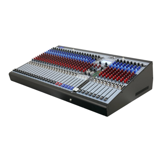
- Page 1 2 Mixer Series ™ 2 32 Channel • Four-Bus Mixing Consoles ™ www.peavey.com...
- Page 2 Congratulations on purchasing the Peavey FX 2 32, four-bus console mixer. These studio-quality mixing ™ consoles are designed to meet diverse needs and feature Peavey-exclusive technology that enhances live studio reproduction as well as project studio recording. FX ™ Series mixers also feature built-in DSP effects that are useful in real-world recording and sound reinforcement, while parameter controls allow you to tailor each effect to meet your needs.
-
Page 3: Mono Input Channels
Front Panel MONO INPUT CHANNELS Gain This control establishes the nominal operating level for the channel. The input gain can be adjusted over a wide range (0 dB – 60 dB) to compensate for soft voices or very loud drums. To maximize the signal-to-noise ratio, the gain should be set to the proper level, with the Channel Fader (13) set to 0. - Page 4 Front Panel This control determines the signal’s position with respect to the assigned L/R and Group 1–4 buses. Rotating the control counterclockwise increases the amount of signal sent to L and odd-numbered groups; rotating clock- wise increases the amount sent to R and even-numbered groups. For ex- ample, with the channel Bus Assign switch (10) in the 1/2 position, rotating the control counterclockwise increases the amount of signal sent to Group 1, while rotating clockwise increases the amount sent to Group 2.
-
Page 5: Stereo Input Channels
Front Panel STEREO INPUT CHANNELS Mic Gain This control establishes the nominal operating level for the mic input Stereo Input Channels (XLR) of the channel. The mic gain can be adjusted over a wide range (0 ONLY dB – 60 dB) to compensate for soft voices or very loud drums. To maxi- mize the signal-to-noise ratio, the gain should be set to the proper level, with the Channel Fader (13) set to ø. - Page 6 Front Panel Phantom Power Switch This switch applies +48 VDC voltage to the input XLR con- nectors to power condenser microphones requiring phantom power. This switch is recessed into the console and requires a small “tool” such as a pencil or pen tip to activate.
- Page 7 Front Panel AFL Switch/Signal-AFL LED This switch connects the Group’s post-fader signal to the PFL/AFL mix. When the AFL button is in, the Group’s signal can be monitored through the headphones and/or on the PFL/AFL display. A yellow LED in the Master section will blink to indicate that the signal on the Master LED display and the Headphone Output is the PFL/AFL mix.
-
Page 8: Digital Processor
This LED indicates that AC power is supplied to the unit‚ the power switch is on, and the unit is function- ing properly. Lamp 12Vdc These outputs are designed to power gooseneck lamps such as the Peavey ML-1. DIGITAL PROCESSOR Page Select Switches (A-B-C) Use these three switches to select the desired digital processor page that is shown in the LCD Graphics User interface (47) and controlled by the encoders (45) and the soft switches (46). - Page 9 Keep in mind that until you confirm your changes by pressing "save," no alterations have been made to the presets. Peavey engineers programmed your mixer with a variety of the most commonly used presets, which are ready to use right out of the box. However, your FX 2 mixer will only reach its full digital processing potential through your acquired expertise.
-
Page 10: Output Processing
Effects Button. OUTPUT PROCESSING: The Peavey FX series mixers are equipped with Digital output processing on the Left and Right mains outputs. The processing may not be switched to the aux busses. Modes: The FX mixers can operate in any of three (3) output modes. -
Page 11: Processor Modules
DIGITAL PROCESSING ARENA so that an adjustment made to the L output will not make that same adjustment to the R output. This would be handy should the L & R outputs of your system be set up in an asymmetrical fashion (e.g., one speaker stack is set up near a corner and the other centered along a wall). - Page 12 DIGITAL PROCESSING ARENA Delay: Highlight the third box from the left to select the “Delay” and press the “edit” knob down to ad- just the amount of delay desired. You can select the “Lib” button to save the current adjustments to the library or to load from the library.
-
Page 13: Firmware Update
Aux Sends or Bus assignment buttons on that channel strip. FIRMWARE UPDATE From time to time, there will be firmware updates that will address bugs or make performance improve- ments. To update the mixer to the latest firmware, please go to www.peavey.com for instructions. - Page 14 Rear Panel CONNECTIONS Inserts: These jacks are 1/4” Tip/Ring/Sleeve (TRS) connectors that allow external signal processors to be inserted into the Input Channel signal path. Tip=Send; Ring=Return; Sleeve=Ground. One of the on- board effects processors can be patched to any channel with an Insert. Line (1/4”) Inputs: These jacks are 1/4”...
- Page 15 Rear Panel Media In Jacks: The Media Input jacks are set up for a +4 dBu input from a stereo audio media source. The signal feeds the Media In level control (34). Record Output Jacks: The output jacks can provide a +4 dBu output signal to a stereo recording device. The output level is controlled by the Record Output level control (36).
- Page 16 2 Series Specifications ™ Inputs Input Levels Function Input Z Input Gain Bal/ Connector (Ohms min) Setting Min* Nominal** Unbal Max Gain -76 dBu -56 dBu -40 dBu XLR Pin 1 Gnd Microphone 2.2k (60 dB) Pin 2 (+) (150 Ohms) Pin 3 (-) Min Gain -16 dBu...
- Page 17 Outputs Output Levels Function Min Load Connector Bal/ Z (Ω) Nominal Unbal +4 dBu +22 dBu XLR Pin 1 Gnd Pin 2 (+), Pin 3 (-) Master Left/Right +4 dBu +22 dBu 1/4" TRS; Tip (+), Ring (-) Sleeve Ground Groups 1-4 and +4 dBu +22 dBu...
- Page 18 Test Conditions: 120 VAC 60 Hz maintained throughout testing Features and specifications are subject to change without notice. Peavey Electronics Corporation • 5022 Hartley Peavey Dr • Meridian, MS 39305 (601) 483-5365 • FAX (601) 486-1278 • www.peavey.com © 2012 EX000165...
- Page 19 LEFT RIGHT GROUP1 GROUP2 GROUP3 GROUP4 AUX1 AUX2 AUX3 AUX4 AUX5/EFX1 AUX6/EFX2 PFL/AFL PFLCTRL...
Need help?
Do you have a question about the FX 2 Series and is the answer not in the manual?
Questions and answers