Table of Contents
Advertisement
TM
READ AND SAVE THESE INSTRUCTIONS
INTAC
®
Microprocessor Humidifier Controller
Installation Instructions
—————————————————
Operation and Maintenance Manual
% Power 68%
Heaters 1 2 3
002
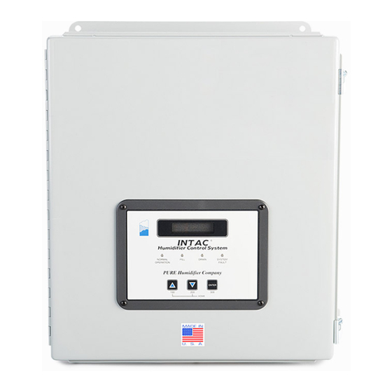
INTAC
®
Humidifier Control System
NORMAL
FILL
DRAIN
SYSTEM
OPERATION
FAULT
PURE Humidifier Co.
ENTER
100
200
300
HOME
Our results are comforting
®
®
PURE HUMIDIFIER
and INTAC
are registered trademarks of PURE Humidifier Co.
1
Form No: INOM-12-19
Advertisement
Table of Contents

Summary of Contents for Pure Humidifier INTAC
- Page 1 Heaters 1 2 3 INTAC ® Humidifier Control System NORMAL FILL DRAIN SYSTEM OPERATION FAULT PURE Humidifier Co. ENTER HOME Our results are comforting ® ® PURE HUMIDIFIER and INTAC are registered trademarks of PURE Humidifier Co. Form No: INOM-12-19...
-
Page 2: Table Of Contents
Table of Contents ® INTAC Specifications ………………………………………………………………... 1 ® INTAC Keypad Features …………………………………………………………….. 2 ® INTAC Menu Overview - How to Navigate ………………………………………… 3 ® INTAC Menus - How to Navigate - Home Display ………………………………... 4 ® INTAC Menus - How to Navigate - 100 & 200 Menus ……………………………. 5 ®... -
Page 3: Intac ® Specifications
INTAC ® Specifications Specifications Supply Voltage: 24VAC ± 20% at 50/60 Hz, ± 1HZ, 9.33VA max. Current Input Impedance: 93 Ohms Voltage Input Impedance: 5000 Ohms Minimum Output Voltage Impedance: 1kOhm Maximum Output Current Impedance: 800 Ohm Termination: Removable screw terminal block... -
Page 4: Intac ® Keypad Features
NORMAL FILL DRAIN SYSTEM OPERATION FAULT PURE Humidifier Co. ENTER HOME Enter Key: Used to toggle/confirm setting once it has been changed and to access the 300 menu “Down” & 200 Menu Key: “Up”... -
Page 5: Intac
® INTAC Menus Overview HOW TO NAVIGATE: Press simultaneously to exit any menu and reach the home display at any time. Press to move up or down through the home display or menu screens. To access a menu, press and hold the corresponding numbered menu key for three (3) seconds. -
Page 6: Intac
® INTAC Menus HOME DISPLAY NORMAL < Normal Operation DISPLAY Safety Circuit Open ERROR AND < ALARM DISPLAYS RH Alarm Low RH Accumulated Run SYSTEM < Time 60 Days OPERATION DISPLAYS Time to Clean 30 Days PRESS TO MOVE Control... - Page 7 HL RH Set Pt THE HOME PARAMETERS 80% RH DISPLAY RH Set Pt 45% RH INTAC Baud Rate 38400 INTAC Address Note: This is a complete listing of all Clean Reset the displays and menu prompts. Not all displays and menu...
- Page 8 RH Input Filter 1 Seconds Duct Derivative 0.00 Minutes Duct Integral 0.00 Minutes per repeat 308 Duct Hysteresis 3% RH PRESS TO MOVE UP OR Duct Prop Band DOWN THRU 25% RH THE HOME DISPLAY Cycle Time 1.0 Seconds Room Derivative 0.00 Minutes Note: This is a complete listing of all...
- Page 9 Menu Access All Menus Unit Capacity Air Process Hi 40 Lbs/Hr 20.00 Milliamps Capacity Unit Air Process Lo Lbs/Hr 4.00 Milliamps Temperature Unit Air Sensor Fahrenheit Current Dedicated Input HL Process Hi Pnl Lockout 10.0 Volts Out Process Hi HL Process Lo 10.00 Volts 0.0 Volts Out Process Lo...
-
Page 10: Intac
Pressurized steam is introduced through a steam control valve into a heat exchanger submerged ® in water. The valve modulation is controlled by an electric actuator. The INTAC will control the electric actuator with an analog control signal to modulate the amount of steam entering the heat exchanger which will in turn control the amount of steam production on the outside of the heat exchanger. -
Page 11: Intac
The process the ® INTAC goes through to accomplish this is called the Automatic Timed Drain. By default the humidifier begins counting run time whenever the humidifier output is greater than 0%. -
Page 12: Pid Control Loop Tuning
PID CONTROL LOOP TUNING For most humidification applications, the parameters in a humidifier control loop that are based off of a room humidity sensor or return air humidity sensor should be set so that the % demand signal changes relatively slowly. This is due to the high thermal inertia involved with boiling water. - Page 13 ® humidistat when the supply air temperature or volumetric flow are change abruptly. The INTAC is always comparing the room/return air humidity and the supply air humidity and choosing control loop the results in the lowest power level.
- Page 14 Low range limits are set correctly. If a slight calibration is desired, proceed as follows: ® First, determine if the INTAC indication is too high or too low and by how many degrees. This can be checked by using a probe-type thermometer located near the air temp sensor and comparing the readings.
-
Page 15: Intac ® Terminal Board Connections
Gold Gold White White Green Green OUTER BOARD ® ® BACK SIDE OF THE INTAC CONTROLLER MOUNTED ON THE PANEL DOOR * Factory Option - This is a fixed value and can not be field modified. Factory set option only. - Page 16 For job specific wiring diagram please reference the materials packet or control panel shipped with the equipment. COMMON (-) MODULATING HIGH LIMIT RELATIVE HUMIDITY INPUT * Factory Option Enabled in menu 707 and Configured in Menus 508 thru 510 CURRENT (+) Input is functional only when menu 502 is set to "Transmitter"...
-
Page 17: Intac ® Hardware Layout
INTAC ® Hardware Layout (HC Model Shown) XFMRS 0004-0330-0000 0726 Inner Circuit Board Outer Circuit Board Terminal Strips DCLMB - Dual Control Loop Module B WLCM - Water Level Control Module DCLMA - Dual Control Loop Module A... -
Page 18: Modbus Modbus Register Map
® INTAC Modbus Map Modbus ® Register INTAC Menu Number Number Number Menu Title Description Accumulated Run Time 0-365 days Outdoor Air Temp Actual -1000-10,000 implied tenths Water Temp Actual -130- 2660, implied tenths High Limit RH Actual 0-1000, implied tenths... -
Page 19: Intac ® Error Code Summary
® INTAC Error Code Summary E01 Safety Circuit Open An open circuit exists in the Safety Circuit. Check the following: Terminals J6-5 & J6-6 High Limit Humidistat Terminals J6-4 & J6-3 Air Flow Switch Terminals J6-2 & J6-1 Over-Temp Switch*... - Page 20 E04 High Limit RH Under Range Check for lost signal from the Hi-Limit Humidistat or Building Management System. Verify that Menus 502, 508, 509, & 510 match the type of input Check signal at the input terminals: Terminal J4-5 = Voltage (+) Input Terminal J4-7 = Voltage (-) / Current (-) Input Terminal J4-6 = Current (+) Input E04 High Limit RH Over Range...
- Page 21 Check water source supply. Verify that water is actually filling the tank to the TOP water level probe. Note: To reset this alarm message, momentarily switch the power off and ® on to the INTAC Controller. E07 H2O Level-Low Tri-Probe application only...
- Page 22 Check water source supply. Verify that water is actually filling the tank to the TOP water level probe. Note: To reset this alarm message, momentarily switch the power off and on to the INTAC ® Controller. E07 H2O Level-Drain Fault Unit did not drain properly during drain cycle.
-
Page 23: Intac
® INTAC Configuration Codes Complete Listing ® INTAC DISPLAY OPTIONS DESCRIPTION MENU DEFAULT RH Set Pt RANGE: 0% to 100% RH Space or return air humidification setpoint HL RH Set Pt RANGE: 0% to 100% RH Supply air high-limit setpoint... - Page 24 DISPLAY OPTIONS DESCRIPTION MENU DEFAULT INTAC Address RANGE: 1 to 247 Modbus Address for external RS-485 network INTAC Baud Rate 9600 19200 38400 Room Prop Band* RANGE: 0% to 100% RH Space or return air proportional band Room Hysteresis* RANGE: 1 to 50...
- Page 25 Offset to calibrate temperature sensor to outside air temp in degrees Celsius ® Process Output Current Output signal (mA DC) for device or actuator—INTAC Plug J3 terminal 5 and 6 ® Voltage Output signal (VDC) for device or actuator—INTAC Plug J3 terminal 4 and 6 Out Process Lo RANGE:0.00 to 8.00 mA...
- Page 26 ® INTAC DISPLAY OPTIONS DESCRIPTION MENU DEFAULT Out Process Hi RANGE: 10.00 to 20.00 mA 20.00 Process output signal—High range in Milliamps RANGE: 3.00 to 10.00 10.00 Process output signal—High range in Volts Dedicated Input Not Used Dedicated input turned off ®...
- Page 27 No tank drain available Hi-Limit Enable Option Modulating Hi-Limit sensor input OFF ® (Factory option only) Modulating Hi-Limit sensor input ON (INTAC plug J4 termi- nals 5,6 and 7) Clean Time Accum Time Auto drain timer counts down when heater output is on...
- Page 28 ® INTAC DISPLAY OPTIONS DESCRIPTION MENU DEFAULT Burner 3 Set Point RANGE: 5 to 100% % power at which burner #3 turns on (Factory option only) Burner 3 Hys RANGE: 1 to 99% % power below Burner #3 set point at which burner #2 turns...
-
Page 29: Notes
Notes Action Performed Date... - Page 32 141 Jonathan Blvd. North Chaska, MN 55318 Tel: (952) 368-9335 Fax: (952) 368-9338 www.purehumidifier.com...
Need help?
Do you have a question about the INTAC and is the answer not in the manual?
Questions and answers