
Related Manuals for Grundfos Conex DIA-2Q

Summary of Contents for Grundfos Conex DIA-2Q
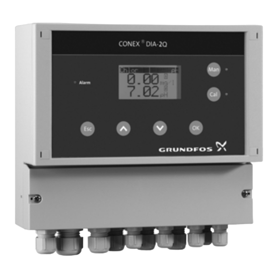
- Page 1 GRUNDFOS INSTRUCTIONS Conex DIA-2Q ® Instrument amplifier and controller Installation and operating instructions...
-
Page 2: Table Of Contents
Applications practice. Safety Obligations of the owner/operations These complete installation and operating manager Note instructions are also available on Avoidance of danger www.Grundfos.com. Identification 1. Symbols used in this document Nameplate ® Type key, Conex DIA-2Q controllers ® Warning Type key, Conex... -
Page 3: A Few Words In Advance
2. A few words in advance ® The Conex DIA-2Q is a multipurpose device designed to carry out high-precision measurements and controls of the following: • a value from parameter group 1: – chlorine, chlorine dioxide, ozone, hydrogen peroxide or peracetic acid •... -
Page 4: Instrument Settings
3. Instrument settings Parameter 1 Setup Controller Alarm Proportional Xp Alarm Parameter Controller On:_ Off:_ Proport. contrl. Chlorine:_ Current input Reset time TN Alarm value 1 Chlorine dioxide:_ Proport. variable (PI/PID control) Switching point Ozone:_ Off:_ Peroxide:_ 0-20 mA:_ sec. Peracetic acid:_ 4- 20 mA:_ Others:_ ________... - Page 5 Parameter 2 Setup Controller Alarm Proportional Xp Alarm Parameter Controller On:_ Off:_ Proport. contrl. Current input Reset time TN Alarm value 1 Proport. variable (PI/PID control) pH:_ Switching point Off:_ Redox:_ 0-20 mA:_ sec. 4- 20 mA:_ Others:_ _______ Deriv. action TV Alarm value 1 Temp.
-
Page 6: General Information
Grundfos. We • They have been trained in use of the device. shall be pleased to support you with our comprehensive know-how in the fields of measuring •... -
Page 7: Identification
7. Identification 7.1 Nameplate DIA-2Q-A D2-X-AU-PCX-Q5-T, W-G 314-935-18008 S/N: 07/33675 Conex DIA-2Q, pre-assembled 230/240V 50/60Hz, 15VA IP 65 95700433P1107190733675 ® Fig. 1 Nameplate, Conex DIA-2Q Pos. Description Type designation Model Product name Voltage [V] Frequency [Hz] Product number Country of origin Year and week of production Marks of approval, CE mark, etc. -
Page 8: Type Key, Conex ® Dia-2Q Controllers
® 7.2 Type key, Conex DIA-2Q controllers Type key example: DIA-2Q, 1-D/HP/PA 2-P/R/F, Q-W-G Example: DIA -2Q 1-D/HP/PA 2-P/R/F Measuring amplifier and controller Dosing Instrumentation Advanced with 2 inputs + flow DIA-2Q measurement Input parameter 1 Chlorine (Cl ), chlorine dioxide (ClO ) or ozone (O Hydrogen peroxide (H Peracetic acid (PAA) - Page 9 Example: DIA -2Q -A -X -AU -PCX -QS Disinfection electrodes Gold Platinum No disinfection measuring Other electrodes pH, ceramic diaphragm, incl. buffer solution pH, PTFE diaphragm, incl. buffer solution pH, KCl filling, incl. buffer solution pH, gel filling incl. buffer solution pH, ceramic diaphragm, excl.
-
Page 10: Technical Data
8. Technical data 8.3 Electronic data and functions 8.3.1 Electronics 8.1 Design/enclosure class Electronics 16-bit microprocessor Wall-mounted High-resolution graphics LCD enclosure Display with background light (distance from IP65 sensors up to three 1 alarm relay, 2 controller Potential-free relay metres) relays (250 V/6 A, maximum outputs 550 VA) - Page 11 8.3.3 Proportional controller functions 8.3.4 Setpoint controller functions Limit monitor, interpulse 0-20 mA/4-20 mA or other Proportional value controller (P, PI, PID), pulse value (freely adjustable input Controller output frequency controller (P, PI, between 0 mA and 20 mA) PID), continuous controller (P, Proportional or inversely PI, PID) Controller output...
-
Page 12: Measuring Ranges
8.4 Measuring ranges Peracetic Redox (ORP) Pt100 acid mg/l mg/l mg/l mg/l mg/l °C 0.00 - 0.50 0.00 - 0.50 0.00 - 0.50 0-100 0-100 0.00 - 14.00 - 1500 to + 1500 -5 to +120 0.00 - 1.00 0.00 - 1.00 0.00 - 1.00 0-500 0-500... -
Page 13: Installation
9. Installation 9.4 Installation in control panel 9.1 Transport and storage > 20 • Transport the device carefully, do not drop! • Store at dry and cool location. +0.8 9.2 Unpacking +0.8 • Check the device for damage. Install as soon as possible after unpacking. >... -
Page 14: Installation Of Wall-Mounted Enclosure
9.5 Installation of wall-mounted enclosure Warning Switch off the power supply before installing! Enclosure class IP65 is only guaranteed if the terminal cover is correctly sealed, if the front panel of the terminal enclosure is closed and the appropriate cable glands or dummy caps fitted. -
Page 15: Commissioning/Electrical Connections
10. Commissioning/electrical connections Warning Switch off the power supply before installing! Enclosure class IP65 is only guaranteed with the front panel of the terminals enclosure closed and with appropriate cable glands or dummy caps. Warning Switch off the power supply before connecting the power supply cable and the relay contacts! For safety reasons, the protective conductor must be connected... -
Page 16: Terminals
10.1 Terminals ® 10.1.1 Wall-mounted enclosure Conex DIA-2Q Fig. 8 Terminals of wall-mounted enclosure... - Page 17 ® 10.1.2 Control panel enclosure Conex DIA-2Q Fig. 9 Terminals of control panel enclosure...
-
Page 18: Power Supply Connection
Legend of terminals 10.2 Power supply connection 1. Control panel enclosure: Plug the plug strip into Pos. Description the corresponding terminal strip at the rear side of the device. Ensure correct orientation. Relays Relay 1 + 2 2. Connect the protective earth conductor (PE) to Alarm relay terminal 5 (wall-mounted enclosure) or terminal –... -
Page 19: Current Output
10.4 Current output Output 4: continuous control parameter 1 This current output shows the calculated actuating Make sure that the polarity of the current variable signal as an analog current signal. output is correct! Caution Use of actuating variable signal: Maximum load: 500 Ω. -
Page 20: Connection Of Measuring Cells
10.6 Connection of measuring cells 37 38 39 40 Jumper setting • All cell types: position 1 (standard). Standard Fig. 11 Jumper setting 10.6.1 Connection of wall-mounted enclosure ® Conex DIA-2Q 15 17 19 21 23 25 27 29 31 33 35 37 38 39 40 41 42 Fig. - Page 21 M B/R Pt 100 37 38 39 40 41 42 Fig. 17 Connection to single-rod measuring chains for pH, redox Pos. Description Conex Sensor interface Brown White Black Blue Fig. 19 Connection to measuring cell Screen AQC-D11 Outer conductor (screen) Inner conductor M B/R Pt 100...
- Page 22 Pos. Description M B/R Pt 100 Brown White Black Blue Screen Outer conductor (screen) Inner conductor Reference electrode Measuring electrode Counter electrode Conex Pt100 temperature sensor Sensor interface Water sensor Outer conductor Yellow Green Fig. 21 Connection to measuring cell AQC-D13 Peculiarities for the connection at the control ®...
- Page 23 ® Connecting the sensor interface to the Conex DIA-2Q (see back side of device) • Measuring cells AQC-D1/-D11/AQC-D2/-D12/AQC-D3/-D13, PAA (peracetic acid)/HP (peroxide) Connect terminals 4/1 to 4/14 of the sensor interface to the corresponding terminals of the ® Conex DIA-2Q. •...
-
Page 24: Operation
11. Operation 11.1 Control and display elements 7 8 1 6 5 4 Fig. 25 Wall-mounted enclosure and control panel enclosure 11.2 Display elements during initial Pos. Description commissioning When connected to the power supply on the device’s Control elements initial commissioning and following the start-up Red alarm LED indication, the display shows the "Sprache/language"... - Page 25 The translations for the words "setup" and • On upward or downward violation of the selected "language" into the currently available languages measuring range, the display will show the upper are: or lower limit and flash. See sections 8.4 Measuring ranges Deutsch 11.5.4 Setting the measuring ranges for chlorine, chlorine dioxide, ozone, peroxide, peracetic acid,...
-
Page 26: Software Overview
Display with one parameter 11.3 Software overview Provided that the code numbers for access right have been set, some menus (and submenus) as well as the functions Cal 0.30 Note and Man are protected against mg/l unauthorised access. The protected menus are marked with "C"... -
Page 27: Main Menu
Setup Selecting the functions "calibration" and "manual operation" "F" (full rights) See the buttons [Cal] and [Man] to the right of the • Selecting language display. • Parameter 1/2: selecting measured values • Calibration: Press [Cal] to switch to the •... -
Page 28: Setup
11.5 Setup All standard settings of the device can be defined in the "setup" menu. During initial commissioning, basic functions are configured which after that should only be altered rarely or even not at all. The "setup" menu can only be accessed by persons having full rights. - Page 29 11.5.2 pH and temperature compensation 11.5.3 Selection of measuring cell pH compensation with chlorine measurement The "measuring cell" submenu is shown The dissociation of hypochlorous acid (HOCl) into only if the measured values chlorine, Note the hypochlorit-anion (OCl ) leads to a loss of slope chlorine dioxide or ozone were selected (loss of sensitivity) of the sensor for chlorine during the parameterisation.
- Page 30 11.5.4 Setting the measuring ranges for chlorine, 11.5.7 Setting the current time (date/time/summer chlorine dioxide, ozone, peroxide, time) peracetic acid, pH, redox 1. Switch from the "setup" menu to the "date/time" In the "measuring ranges" menu, the corresponding menu. measuring ranges are assigned to the measured values which have been selected in the "parameters"...
- Page 31 11.5.8 Code function • If no code was entered previously, the desired menu can be accessed without restrictions. The The code function is designed to protect the device code number 0000 will not be displayed/the from unauthorised access. operator will not be asked to enter it. Entering the four-digit code number and changing it If a wrong code is entered, access to the...
- Page 32 11.5.11 Factory setting reset ® In the "factory setting" submenu, the Conex DIA-2Q can also be reset to the factory setting using code 6742. Only use this function in an emergency. All device settings are lost and must be re-entered! Caution Do not disconnect the device from the power supply during the reset!
- Page 33 2 program version • Output 4: continuous controller for parameters from group 1. Assignment of the current outputs to the Conex DIA-2Q measuring range (example: chlorine measurement) v0.20.1 20030304 There are two standard ranges, "0-20 mA" and "4-20 mA"...
-
Page 34: Selection, Configuration And Parameterisation Of The Controller
11.6 Selection, configuration and parameterisation of the controller It takes two steps to set up the controller: • First: selection and configuration of the controller type in the "setup" menu, "controller" submenu. • Second: parameterisation of the selected controller type in "main menu", "controller" submenu. - Page 35 Selection and configuration of the proportional 5. Use the [Up] and [Down] buttons to select the controller control response as one of the following: 1. Mark the "proport. contrl" line using the [Up] and – P (proportional controller), [Down] buttons, and select using [OK]. –...
- Page 36 11.6.2 Setting the controller parameters 1. Select a controller in the "setup" menu and configure it. See section 11.5.5 Controller parameters 1/2. 2. Select the line "controller" in "main menu" using the [Up] and [Down] buttons, and press [OK] to switch to the "controller"...
- Page 37 main menu controller parameter 1/2 settings in the setup menu setpoint contrl setpoint contrl setpoint contrl setpoint contrl cont. controller interpulse ctrl. pulse freq. contrl. limit contact limit setpoint setpoint setpoint hysteresis prop. band xp prop. band xp prop. band xp stop reset time TN** reset time TN**...
- Page 38 11.6.3 Controller control fields on the display 1. Press [Esc] once or twice to switch to the display "measured value". See sections 8.2 General data 11.2.1 Display modes. controller control fields chlorine continuous controller output relay 1 or 2 0.43 mg/l proportional disturbance variable 5.20 pH...
- Page 39 11.6.4 Adaptation An adaptation can be started to simplify the setting of the controller parameters. The adaptation is only available for PI and PID controllers. 1. Start adaptation in the "controller" menu (main menu) under "adaptation" by pressing "start". chlorine 0.43 mg/l adaptation...
-
Page 40: Alarm" Menu
11.7 "Alarm" menu With the help of the alarm function, the measured value can be monitored and compared with the permitted range. If the measured value exceeds the limits of the measuring range, an alarm is triggered. • The alarm relay is deactivated after the selected alarm delay time. - Page 41 11.7.2 Setting the upper and lower switching 9. Select the line "alarm delay" in the "alarm values" point (limits) menu, and press [OK] in the corresponding submenu. 1. Select the line "alarm value 1" or "alarm value 2". Press [OK] to confirm and switch to the desired menu.
-
Page 42: Checking The Settings In The "Service" Menu
11.8 Checking the settings in the "service" menu In the "service" menu, the operator can check all important settings and test the functions of the device in the event of problems that make service necessary. In the "service" menu, calibration data and controller settings cannot be altered. - Page 43 Notes to figures in fig. 37: Under water sensor, the following data are displayed: "cal temp." will only be displayed if • speed of the water sensor during the last temperature measurement or temperature calibration compensation has been switched on in the •...
-
Page 44: Calibration
Caution reference value. Therefore the pH value must be calibrated first! Only then calibrate the chlorine value! 11.9.2 Calibrating the pH value "Cal" cal. meas. GRUNDFOS value temperature DIN/NIST of buffer buffer 1/2 solution automatic reading of others... - Page 45 Selecting buffer types and buffer values, reading buffer value 2 in buffer values and calibrating Three optional buffer types are available: • GRUNDFOS: buffer values pH 4.01, 7.00, 9.18. • DIN/NIST: buffer values pH 4.01, 6.86, 9.18. 7.00 pH •...
- Page 46 Error messages during the reading in of the Cal. cycle voltage signal of the pH electrode • Following selection of "cal. cycle" in the The calibration may be aborted in the following "measured value" menu, a countdown function is cases: started which triggers the alarm signal "calibrate sensor"...
- Page 47 If redox is selected, the [Cal] button is out of 0.45 mg/l function. • To check a single-rod measuring chain for redox, I-cell 10.4 µA use a special redox buffer (for example Grundfos redox buffer 220 mV, product number: 96609166).
-
Page 48: Manual Operation
11.10 Manual operation The manual operation mode is used to switch off the automatic control and run the control relays manually. Manual operation is only possible after a controller has been configured. Note Manual operation can only be accessed with calibration rights or full rights. 1. - Page 49 11.10.1 Manual operation with configured two-position and continuous controllers "Man" controller dosing flow manual relay 1 stop 0-100 % operation dosing flow relay 2 0-100 % Fig. 40 Manual operation with configured two-position and continuous controllers With configured two-position controllers, the relay 3.
- Page 50 11.10.2 Manual operation with configured limit contact and continuous controller "Man" manual controller relay 1/2 operation stop cont. controller dosing flow 0-100 % Fig. 41 Manual operation with configured limit contact and continuous controller Manual operation with configured limit contacts is largely similar to manual operation with two-position controllers and continuous controllers.
-
Page 51: Fault Finding
This product or parts of it must be disposed of in an environmentally sound way. Use appropriate waste Repairs can only be carried out in the factory by collection services. If this is not possible, contact the authorised personnel. nearest Grundfos company or service workshop. - Page 52 Declaration of conformity GB: EU declaration of conformity BG: Декларация за съответствие на EO We, Grundfos, declare under our sole responsibility that the products Ние, фирма Grundfos, заявяваме с пълна отговорност, че Conex® DIA-1, DIA-2, DIA-2Q, to which the declaration below продуктите...
- Page 54 Argentina China Germany Bombas GRUNDFOS de Argentina S.A. Grundfos Alldos GRUNDFOS Water Treatment GmbH Ruta Panamericana km. 37.500 Centro Dosing & Disinfection Reetzstraße 85 Industrial Garin ALLDOS (Shanghai) Water Technology D-76327 Pfinztal (Söllingen) 1619 - Garin Pcia. de B.A. Co. Ltd.
- Page 55 Phone: +40 21 200 4100 Telefax: +66-2-725 8998 Phone: +82-2-5317 600 Telefax: +40 21 200 4101 Turkey Telefax: +82-2-5633 725 E-mail: romania@grundfos.ro GRUNDFOS POMPA San. ve Tic. Ltd. Latvia Russia Sti. SIA GRUNDFOS Pumps Latvia ООО Грундфос Россия Gebze Organize Sanayi Bölgesi Deglava biznesa centrs ул.
- Page 56 96681468 0419 ECM: 1260226 www.grundfos.com...
Need help?
Do you have a question about the Conex DIA-2Q and is the answer not in the manual?
Questions and answers