Table of Contents
Advertisement
Swing-Away Grain Auger
MKX 13
Assembly Manual
This manual applies to:
MKX 13-64, MKX 13-74
Original Instructions
Read this manual before using product. Failure to
follow instructions and safety precautions can
result in serious injury, death, or property
damage. Keep manual for future reference.
Part Number: 30796 R7
Revised: January 2020
Advertisement
Table of Contents

Related Manuals for AGI WESTFIELD MKX 13 Series

Summary of Contents for AGI WESTFIELD MKX 13 Series
- Page 1 Swing-Away Grain Auger MKX 13 Assembly Manual This manual applies to: MKX 13-64, MKX 13-74 Original Instructions Read this manual before using product. Failure to Part Number: 30796 R7 follow instructions and safety precautions can Revised: January 2020 result in serious injury, death, or property damage.
- Page 2 New in this Manual The following changes have been made in this revision of the manual: Description Section New spout design Section 4.11 – Install the Spout on page 33 Hubs pre-installed on axle Section 4.14 – Assemble the Frame on page 39 Added 15' swing tube assembly Section 4.19 –...
-
Page 3: Table Of Contents
SWING-AWAY GRAIN AUGER – MKX 13 CONTENTS 1. Introduction ............................5 2. Safety............................... 6 2.1 Safety Alert Symbol and Signal Words..................6 2.2 General Product Safety ......................6 2.3 Rotating Flighting Safety ......................7 2.4 Rotating Parts Safety......................... 7 2.5 Hand Winch Safety ........................7 2.6 Hydraulic Winch Safety ...................... - Page 4 SWING-AWAY GRAIN AUGER – MKX 13 6.1 Bolt Torque..........................59 30796 R7...
-
Page 5: Introduction
SWING-AWAY GRAIN AUGER – MKX 13 1. INTRODUCTION 1 1 . . I I n n t t r r o o d d u u c c t t i i o o n n This manual describes how to assemble a Westfield Swing-Away Grain Auger. Before assembling, please read this manual. -
Page 6: Safety
2. SAFETY SWING-AWAY GRAIN AUGER – MKX 13 2 2 . . S S a a f f e e t t y y 2.1. Safety Alert Symbol and Signal Words This safety alert symbol indicates important safety messages in this manual. When you see this symbol, be alert to the possibility of injury or death, carefully read the message that follows, and inform others. -
Page 7: Rotating Flighting Safety
SWING-AWAY GRAIN AUGER – MKX 13 2. SAFETY 2.3. Rotating Flighting Safety • KEEP AWAY from rotating flighting. • DO NOT remove or modify flighting guards, doors, or covers. Keep in good working order. Have replaced if damaged. • DO NOT operate the auger without all guards, doors, and covers in place. -
Page 8: Hydraulic Winch Safety
2. SAFETY SWING-AWAY GRAIN AUGER – MKX 13 2.6. Hydraulic Winch Safety When Equipped: • Keep away from rotating cable drum and winch cable. Do not touch or grab cable while winch is being operated or use hands to guide the cable. Failure to heed could result in serious injury. -
Page 9: Hydraulic Power Safety
SWING-AWAY GRAIN AUGER – MKX 13 2. SAFETY 2.7.2 Hydraulic Power Safety Power Source • Refer to the rules and regulations applicable to the power source operating your hydraulic drive. • Do not connect or disconnect hydraulic lines while system is under pressure. -
Page 10: Tire Safety
2. SAFETY SWING-AWAY GRAIN AUGER – MKX 13 2.8. Tire Safety Failure to follow proper procedures when mounting a tire on a wheel or rim can produce an explosion that may result in serious injury or death. • DO NOT attempt to mount a tire unless you have the proper equipment and experience to do the job. -
Page 11: Safety Equipment
SWING-AWAY GRAIN AUGER – MKX 13 2. SAFETY Steel-Toe Boots • Wear steel-toe boots to protect feet from falling debris. Work Gloves • Wear work gloves to protect your hands from sharp and rough edges. Dust Mask • Wear a dust mask to prevent breathing potentially harmful dust. Hearing Protection •... -
Page 12: Decal Installation/Replacement
2. SAFETY SWING-AWAY GRAIN AUGER – MKX 13 2.11.1 Decal Installation/Replacement 1. Decal area must be clean and dry, with a temperature above 50°F (10°C). 2. Decide on the exact position before you remove the backing paper. 3. Align the decal over the specified area and carefully press the small portion with the exposed sticky backing in place. - Page 13 SWING-AWAY GRAIN AUGER – MKX 13 2. SAFETY Table 1. Safety Decals Part Number Description 20813 DANGER ROTATING FLIGHTING HAZARD To prevent death or serious injury: • KEEP AWAY from rotating auger flighting. • DO NOT remove or modify auger flighting guards, doors, or covers.
- Page 14 2. SAFETY SWING-AWAY GRAIN AUGER – MKX 13 Table 1 Safety Decals (continued) Part Number Description 20816 DANGER ELECTROCUTION HAZARD To prevent death or serious injury: • When operating or moving, keep equipment away from overhead power lines and devices. •...
- Page 15 SWING-AWAY GRAIN AUGER – MKX 13 2. SAFETY Table 1 Safety Decals (continued) Part Number Description 17094 DANGER ROTATING FLIGHTING INSIDE To prevent serious injury or death, do not operate auger unless swing- hopper is securely attached to boot. 30796 R7...
- Page 16 2. SAFETY SWING-AWAY GRAIN AUGER – MKX 13 Table 1 Safety Decals (continued) Part Number Description 20807 WARNING To prevent serious injury or death: • Read and understand the manual before assembling, operating, or maintaining the equipment. • Only trained personnel may assemble, operate, or maintain the equipment.
- Page 17 SWING-AWAY GRAIN AUGER – MKX 13 2. SAFETY Table 1 Safety Decals (continued) Part Number Description 20811 WARNING UPENDING HAZARD To prevent death or serious injury: • Anchor intake end and/or support discharge end to prevent upending. • Intake end must always have downward weight. Do not release until attached to tow bar or resting on ground.
- Page 18 2. SAFETY SWING-AWAY GRAIN AUGER – MKX 13 Table 1 Safety Decals (continued) Part Number Description 20805 WARNING HIGH PRESSURE FLUID HAZARD Hydraulic fluid can cause serious injury if it Hydraulic fluid can cause serious injury if it penetrates the skin. If it does, see a doctor penetrates the skin.
- Page 19 SWING-AWAY GRAIN AUGER – MKX 13 2. SAFETY Table 1 Safety Decals (continued) Part Number Description 20804 WARNING ENTANGLEMENT HAZARD To prevent serious injury or death: • Keep body, hair, and clothing away from rotating pulleys, belts, chains, and sprockets. •...
- Page 20 2. SAFETY SWING-AWAY GRAIN AUGER – MKX 13 Table 1 Safety Decals (continued) Part Number Description 17107 CAUTION To prevent personal injury or damage to equipment, close valve in lift cylinder hydraulic line after raising equipment into position. 19960 NOTICE To prevent damage, wheels must be free to move when raising or lowering equipment.
- Page 21 SWING-AWAY GRAIN AUGER – MKX 13 2. SAFETY Table 1 Safety Decals (continued) Part Number Description 17531 NOTICE To prevent damage during auger- to-tractor hookup: • Follow dimensions above for correct auger-to-tractor hookup. • Auger must be on level ground and in full down position when measuring.
-
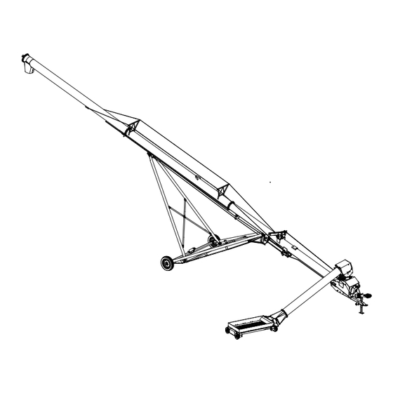
Page 22: Features
3. FEATURES SWING-AWAY GRAIN AUGER – MKX 13 3 3 . . F F e e a a t t u u r r e e s s This section covers the main features of the auger. Discharge Spout Stabilizer Brace Truss Tower Track Boot... - Page 23 SWING-AWAY GRAIN AUGER – MKX 13 3. FEATURES Swing Features Spout Head Swing Arm Maintenance Hatch Hopper Flights and Flight Guarding Grain Transfer Boot Features Hitch Jack Hitch PTO Driveline Ball Valve Clean-Out Hatch Grain Transfer Boot Manual Winch (Hopper) Manual Holder 30796 R7...
-
Page 24: Assembly
4. ASSEMBLY SWING-AWAY GRAIN AUGER – MKX 13 4 4 . . A A s s s s e e m m b b l l y y Before continuing, ensure you have completely read and understood this manual’s Safety section, in addition to the safety information in the section(s) below. 4.1. -
Page 25: Brand And Model Decal Placement
SWING-AWAY GRAIN AUGER – MKX 13 4. ASSEMBLY 4.4. Brand and Model Decal Placement Important Do not cover any existing safety or instruction decals with the model decals. 1. Apply decals to both sides of auger tube. 2. Center decals vertically and apply to auger tube. Brand Decal Location UPPER TUBE BRAND DECAL... -
Page 26: Install Hydraulic Lift Cylinders
4. ASSEMBLY SWING-AWAY GRAIN AUGER – MKX 13 64' Models LOWER TUBE MIDDLE TUBE UPPER TUBE 74' Models LOWER TUBE LOWER MIDDLE TUBE UPPER MIDDLE TUBE UPPER TUBE 4.6. Install Hydraulic Lift Cylinders 1. Identify the tube section where the hydraulic lift cylinders install, and rotate the section so that the cylinder mount brackets are facing up. -
Page 27: Connect Auger Tube Sections Together
SWING-AWAY GRAIN AUGER – MKX 13 4. ASSEMBLY 5. Strap the tube in place and proceed with connecting auger tube sections together. Figure 1. Installing Lift Cylinders 7/16” X 1-1/4” BOLTS 7/16” LOCKNUTS 4.7. Connect Auger Tube Sections Together Important Always strap tubes to the support stands to prevent the tubes from rolling off the stands. -
Page 28: Install The Track Shoe, Trackstop, And Cable Roller
4. ASSEMBLY SWING-AWAY GRAIN AUGER – MKX 13 Figure 2. Connecting Auger Tubes Sections and Flights 1/2” X 4” BOLT 7/16” X 1-1/4” BOLTS 1/2” LOCKNUT 7/16” LOCKNUTS USE A STRAIGHT EDGE TO ALIGN TRACKS AT JOINT TO ENSURE SMOOTH SLIDE FOR TRACK SHOE 4.8. - Page 29 SWING-AWAY GRAIN AUGER – MKX 13 4. ASSEMBLY Figure 3. MKX13–64 Track Shoe, Cable Roller, and Track-Stop NOTE: ALL BOLTS ARE 7/16” X 1-1/4” ALL NUTS ARE 7/16” LOCKNUTS TRACK SHOE CABLE ROLLER ANGLE TRACK-STOP FLAT-IRON TRACK-STOP 30796 R7...
- Page 30 4. ASSEMBLY SWING-AWAY GRAIN AUGER – MKX 13 Figure 4. MKX13–74 Track Shoe, Cable Roller, and Track-Stop NOTE: ALL BOLTS ARE 7/16” X 1-1/4” ALL NUTS ARE 7/16” LOCKNUTS TRACK SHOE CABLE ROLLER ANGLE TRACK-STOP 30796 R7...
-
Page 31: Install The Boot On The Auger Tube
SWING-AWAY GRAIN AUGER – MKX 13 4. ASSEMBLY 4.9. Install the Boot on the Auger Tube Components are heavy and create a crushing hazard if improperly handled. Be sure to use proper hoisting equipment and procedures, and ensure lifting apparatus is secure. Lock out the lifting apparatus before working around or under the raised components;... - Page 32 4. ASSEMBLY SWING-AWAY GRAIN AUGER – MKX 13 Assembly Notes: • Ensure that the flight shaft shoulder is seated against washer and bearing. • Position the lock collar tightly against the bearing, then tighten the collar set screw. • Align lower sprocket face with upper sprocket face using a straight edge, then tighten set screws. •...
-
Page 33: Install The Boot Tow Bar
SWING-AWAY GRAIN AUGER – MKX 13 4. ASSEMBLY 4.10. Install the Boot Tow Bar Tow Bar Reducer/Reverser Reverser U-Bolt, 3/4" x 3-1/2" x 5" Regular Bolt, 3/4" x 5-1/2" Locknut, 3/4" 4.11. Install the Spout Assembly Note: • Apply caulking to seal the seam of spout to tube. -
Page 34: Set The Thrust Adjuster
4. ASSEMBLY SWING-AWAY GRAIN AUGER – MKX 13 4.12. Set the Thrust Adjuster 1. Remove the upper bearing lock collar (if necessary). Ensure that flight shaft slides freely in/out of bearing. 2. Slide the lock collar and bushing onto the shaft and attach the 1-1/2” nut. 3. - Page 35 SWING-AWAY GRAIN AUGER – MKX 13 4. ASSEMBLY 5. Pull the cable over the truss brackets, around upper truss anchor and back over truss support brackets to the lower truss anchor bracket, holding it loosely in place with one 5/16" cable clamp at upper truss anchor bracket, and two 5/16"...
- Page 36 4. ASSEMBLY SWING-AWAY GRAIN AUGER – MKX 13 Figure 5. MKX13–64 Truss Support and Truss Cable Brackets 7/16” X 1-1/4” BOLTS STANDARD TRUSS BRACKETS 7/16” LOCKNUTS 7/16” LOCKNUTS TRUSS CABLE BRACKET 7/16” X 1-1/4” BOLTS 30796 R7...
- Page 37 SWING-AWAY GRAIN AUGER – MKX 13 4. ASSEMBLY Figure 6. MKX13–64 Truss Cables 5/16” CABLE CLAMP 1/2” EYEBOLT LOWER TRUSS ANCHOR BRACKET UPPER TRUSS ANCHOR BRACKET 1/2” LOCKNUT 5/16” CABLE CLAMP 3/8” CABLE CLAMPS 30796 R7...
- Page 38 4. ASSEMBLY SWING-AWAY GRAIN AUGER – MKX 13 Figure 7. MKX13–74 Truss Support and Truss Cable Brackets STANDARD TRUSS BRACKET 7/16” X 1-1/4” BOLTS HIGH TRUSS BRACKET 7/16” LOCKNUTS 7/16” LOCKNUTS TRUSS CABLE STANDARD TRUSS BRACKET BRACKET 7/16” X 1-1/4” BOLTS 30796 R7...
-
Page 39: Assemble The Frame
SWING-AWAY GRAIN AUGER – MKX 13 4. ASSEMBLY Figure 8. MKX13–74 Truss Cables 5/16” CABLE CLAMP 1/2” EYEBOLT LOWER TRUSS ANCHOR BRACKET UPPER TRUSS ANCHOR BRACKET 5/16” CABLE CLAMP 1/2” LOCKNUT 3/8” CABLE CLAMPS 4.14. Assemble the Frame 1. Fasten the lower reach arms (1, 2) to the axle (3) with three 5/8" x 2" bolts and locknuts on each side. 2. - Page 40 4. ASSEMBLY SWING-AWAY GRAIN AUGER – MKX 13 Figure 9. MKX13-64/74 Lower Frame Table 2. MKX13–64/74 Lower Frame Parts Item Item Description Description Lower Reach Arm, LH Bolt, 1/2" x 1-1/4" Lower Reach Arm, RH Locknut, 1/2" Axle Bolt, 5/8" x 2" Frame Cross Brace Locknut, 5/8"...
-
Page 41: Connect The Auger Tube To The Frame
SWING-AWAY GRAIN AUGER – MKX 13 4. ASSEMBLY 4.15. Connect the Auger Tube to the Frame 1. Raise the discharge end of auger with a front end loader and a strong sling/chain or block and tackle. The height should be sufficient to clear the undercarriage assembly. Do not remove tube support until the assembly in this section has been completed. - Page 42 4. ASSEMBLY SWING-AWAY GRAIN AUGER – MKX 13 Figure 10. Connecting the Auger Tube to Frame (MKX13–64/74) 30796 R7...
-
Page 43: Install The Auger Tube Lift Cylinders And Cables
SWING-AWAY GRAIN AUGER – MKX 13 4. ASSEMBLY Table 3. Parts Required to Connect the Auger Tube to the Frame (MKX13–64/74) Item Item Description Description Stabilizer Bracket, LH Bolt, 1" x 3-1/2" (64' Only) Stabilizer Bracket, RH Bolt, 1" x 3-3/4" (74' Only) Bolt, 1"... -
Page 44: Connect Hydraulic Hoses And Ball Valve
4. ASSEMBLY SWING-AWAY GRAIN AUGER – MKX 13 Figure 11. Connecting the Lift Cylinder Cables to the Track Shoe 5/16” CABLE CLAMPS (THREE PER CABLE) RIGHT-ANGLE TRACK STOP TRACK SHOE CABLE ROLLER HYDRAULIC LIFT CYLINDERS 4.17. Connect Hydraulic Hoses and Ball Valve Note Determine right or left side of auger by standing at intake end facing top discharge end. - Page 45 SWING-AWAY GRAIN AUGER – MKX 13 4. ASSEMBLY 5. Secure the ball valve to the boot using the valve holder and two 1/4” x 3/4” bolts and locknuts (see Figure 14 on page 46). 6. Recheck that bolts on undercarriage, lift cylinders, and cable clamps are tight, then remove auger tube support.
- Page 46 4. ASSEMBLY SWING-AWAY GRAIN AUGER – MKX 13 Figure 13. Hydraulic Diagram for MKX13–64/74 Augers Figure 14. Installing the Ball Valve on the Boot Item Item Description Description Cylinder Hose Assembly Bolt, 1/4" x 3/4" Ball Valve Locknut, 1/4" Valve Holder 30796 R7...
-
Page 47: Connect The Pto Driveline
SWING-AWAY GRAIN AUGER – MKX 13 4. ASSEMBLY 4.18. Connect the PTO Driveline Assembly Note: • Clean paint or dirt off of PTO driveline and flighting shaft ends. PTO Bracket Roll Pin, 3/8" x 2-1/2" Transport Saddle Bolt, 1/2" x 1-1/2" Sprocket Cover Locknut, 1/2"... -
Page 48: Install Low Profile Intake Hopper
4. ASSEMBLY SWING-AWAY GRAIN AUGER – MKX 13 4.19. Install Low Profile Intake Hopper Components are heavy and create a crushing hazard if improperly handled. Be sure to use proper hoisting equipment and procedures, and ensure lifting apparatus is secure. Lockout the lifting apparatus before working around or under the raised components. - Page 49 SWING-AWAY GRAIN AUGER – MKX 13 4. ASSEMBLY Assembly Notes: • Tighten set screws on u-joints, then close and secure the service door. • There are 3 height settings for the hopper wheels that can be used according to preference. Door Pin Wheel Lynch Pin...
- Page 50 4. ASSEMBLY SWING-AWAY GRAIN AUGER – MKX 13 Assembly Notes: • Open the spring clasps and rotate the spout lid open, so that it lies down on the top of the swing tube. • Clean the u-joint spline and splined shaft on the lower gearbox, then apply a light film of grease on this splined shaft.
-
Page 51: Install The Frame Deflector Plates
SWING-AWAY GRAIN AUGER – MKX 13 4. ASSEMBLY 4.20. Install the Frame Deflector Plates For the MKX13-64 auger, install a frame deflector plate assembly on each side of the auger frame to prevent the hopper from impacting the frame when it is lifted into transport position. For both lower reach arms (left side and right side): 1. -
Page 52: Install The Hopper Lift Arm And Winch
4. ASSEMBLY SWING-AWAY GRAIN AUGER – MKX 13 4.21. Install the Hopper Lift Arm and Winch Augers with 10' Swing Tube Assembly (Standard) Assembly Notes: • Determine which side of the auger the hopper will be operating on. • Position the lift arm assembly on top of the auger tube with the arm overhanging the side that the hopper will be operating on. - Page 53 SWING-AWAY GRAIN AUGER – MKX 13 4. ASSEMBLY Augers with 15' Swing Tube Assembly (Optional) This option is only available for 74' models. Assembly Notes: • Determine which side of the auger the hopper will be operating on. • Position the lift arm assembly on top of the auger tube with the arm overhanging the side that the hopper will be operating on.
- Page 54 4. ASSEMBLY SWING-AWAY GRAIN AUGER – MKX 13 Winch Cable Assembly Notes: • Thread the cable through the hopper lift arm and pull the cable to the winch. • Wrap the cable over and around the winch spool at least three times, then insert the cable end through the hole provided in the side of the spool and secure the end with the provided cable clamp.
-
Page 55: Hopper Transport Position
SWING-AWAY GRAIN AUGER – MKX 13 4. ASSEMBLY 4.22. Hopper Transport Position Augers with 10' Swing Tube Assembly (Standard) Assembly Note: • Feed side of hopper must face the main auger when in transport. Safety Chain Winch Cable Augers with 15' Swing Tube Assembly (Optional) This option is only available for 74' models. -
Page 56: Install The Hitch Jack
4. ASSEMBLY SWING-AWAY GRAIN AUGER – MKX 13 4.23. Install the Hitch Jack The jack is attached to the auger with a pin at the pivot point. To install: 1. Elevate the auger boot (intake end) approximately 2’ (5.08 cm) with a front-end loader and sling, and install the jack in a vertical position. -
Page 57: Install The Plastic Manual Container
SWING-AWAY GRAIN AUGER – MKX 13 4. ASSEMBLY 4.24. Install the Plastic Manual Container Assembly Note: • Before beginning installation, ensure that all winch/auger lift controls are locked in place and shut down and/or lock out auger. Boot Self Tapping Screw Plastic Manual Holder 30796 R7... -
Page 58: Specifications
5. SPECIFICATIONS SWING-AWAY GRAIN AUGER – MKX 13 5 5 . . S S p p e e c c i i f f i i c c a a t t i i o o n n s s Specification 13-64 13-74... -
Page 59: Appendix
SWING-AWAY GRAIN AUGER – MKX 13 6. APPENDIX 6 6 . . A A p p p p e e n n d d i i x x 6.1. Bolt Torque Table 4 gives the correct torque values for various hardware. Tighten all bolts to the torque specified, unless otherwise noted. - Page 60 P.O. Box 39 Rosenort, Manitoba, R0G 1W0 Canada Phone: (866) 467-7207 (Canada & USA) or (204) 746–2396 Fax: (866) 768-4852 Website: www.grainaugers.com Email: sales@grainaugers.com ©Ag Growth International Inc. 2020 Printed in Canada If you have any comments or questions on this manual, or find an error, email us at comments@aggrowth.com. Please include the part number listed on the cover page in your message.
Need help?
Do you have a question about the MKX 13 Series and is the answer not in the manual?
Questions and answers