Table of Contents
Advertisement
Quick Links
JLN-740A/740N
JLN-741A/741N
DOPPLER LOG
Instruction Manual
General
Function of Each Components
Operation Method (JLN-740A/741A)
Menu Settings and Configurations
(JLN-740A/741A)
Operation Method (JLN-740N/741N)
Menu Settings and Configurations
(JLN-740N/741N)
Operation Method (Option)
Setting by Using Menus (Option)
Installation Method
Maintenance and Inspection
After-Sales Service
Disposal
Specification
Menu list
Installation Drawings
Error due to the deviation from the
irradiation angle reference value
Spare Parts List
1
2
3
4
5
6
7
8
9
10
11
12
13
APP A
APP B
APP C
APP D
Advertisement
Table of Contents

Summary of Contents for Japan Radio Co. JLN-740A
- Page 1 General Function of Each Components Operation Method (JLN-740A/741A) Menu Settings and Configurations (JLN-740A/741A) Operation Method (JLN-740N/741N) JLN-740A/740N Menu Settings and Configurations (JLN-740N/741N) JLN-741A/741N Operation Method (Option) Setting by Using Menus (Option) DOPPLER LOG Installation Method Maintenance and Inspection After-Sales Service...
- Page 3 Safety Cautions Cautions for High Voltage High voltage of hundreds volts is used inside this equipment. Touching a component inside the unit is very dangerous. Any person other than specialized maintenance staffs should not maintain, inspect, or adjust the unit. High voltages on the order of tens of thousand volts are most likely to cause instant deaths from electrical shocks.
-
Page 4: Emergency Measures
Emergency Measures Method of First-Aid Treatment Precautions for First-Aid Treatments Apply artificial respiration to the person who collapsed, minimizing moving as much as possible avoiding risks. Once started, artificial respiration should be continued rhythmically. (1) Refrain from touching the patient carelessly as a result of the accident; the first-aider could suffer from electrical shocks by himself or herself. - Page 5 Flow of Cardiopulmonary Resuscitation (CPR) A person is collapsing. A person is collapsing. - Secure the safety of the surrounding area. - Secure the safety of the surrounding area. - Prevent secondary disasters. - Prevent secondary disasters. Listen to the appeal of the Responding Check for response.
- Page 6 Specific Procedures for Cardiopulmonary Resuscitation (CPR) 1. Check the scene for safety to prevent secondary disasters a) Do not touch the injured or ill person in panic when an accident has occurred. (Doing so may cause electric shock to the first-aiders.) b) Do not panic and be sure to turn off the power.
- Page 7 b) If the injured or ill person is breathing, place him/her in the recovery position and wait for the arrival of the emergency services. • Position the injured or ill person on his/her side, maintain a clear and open airway by pushing the head backward while positioning their Roll gently in the opposite mouth downward.
- Page 8 2) Perform chest compressions Compress with these • Perform uninterrupted chest compressions of 30 parts (the heels of at the rate of about 100 times per minute. both hands). While locking your elbows positioning yourself vertically above your hands. • With each compression, depress the chest wall to a depth of approximately 4 to 5 cm. b) Combination of 30 chest compressions and 2 rescue breaths 30 times 1) After performing 30 chest compressions, give 2 rescue...
- Page 9 11. Attach the electrode pads to the injured or ill person's bare chest a) Remove all clothing from the chest, abdomen, and arms. b) Open the package of electrode pads, peel the pads off and securely place them on the chest of the injured or ill person, with the adhesive side facing the chest.
- Page 10 15. Automatic electrocardiogram analysis a) When 2 minutes have elapsed since you resumed cardiopulmonary resuscitation (CPR), the AED automatically analyzes the electrocardiogram. b) If you suspended CPR by following voice prompts and AED voice prompt informs you that shock is needed, give electric shock again by following the voice prompts. If AED voice prompt informs you that no shock is needed, immediately resume CPR.
-
Page 11: Table Of Contents
Contents ........................ix Preface........................xv Pictorial Indication ..........................xvi Usage Precautions ........................... xvii JLN-740A Overview of standard components ........... xxiii JLN-740N Overview of standard components ........... xxiv JLN-741A Overview of standard components ............ xxv JLN-741N Overview of standard components ........... xxvi Abbreviations .......................xxvii... - Page 12 SDME Advanced Settings ................4-15 4.1.3.10. Alert List ......................4-15 4.1.3.11. Alert History ...................... 4-16 4.2. Alert ..........................4-17 4.2.1. JLN-740A Alert list ....................4-17 4.2.2. JLN-741A Alert list ....................4-19 4.2.3. Sentence list that generates “ID sentence abnormal(PARSING FAIL)” ....4-20 Chapter 5 Operation Method (JLN-740N/741N) ..............
- Page 13 6.2. System setting ......................6-15 6.3. Language setting ......................6-15 6.4. Alert setting ........................6-15 6.5. Sensor setting ....................... 6-16 6.6. Date and time setting ....................6-16 6.7. Alert history display ....................... 6-16 6.8. Alert list display ......................6-17 6.9. Alert ..........................6-17 6.9.1 Alerts that occur in JLN-741N ..................
- Page 14 13.1.1. JLN-740A ......................... 13-1 13.1.2. JLN-740N ......................... 13-1 13.1.3. JLN-741A ......................... 13-2 13.1.4. JLN-741N ......................... 13-2 13.2. JLN-740A/741A Main Display NWZ-510SDW .............. 13-3 13.2.1. Display Unit ......................13-3 13.2.2. Electrical Specifications ................... 13-3 13.2.3. Environmental Requirements .................. 13-3 13.2.4. Mechanical Specifications ..................13-3 13.2.5.
- Page 15 Electrical Specifications .................. 13-12 13.10.3. Environmental Requirements ................. 13-12 13.10.4. Mechanical Specifications ................13-12 13.11. JLN-740A/N Data Format ..................13-13 13.11.1. IEC 61162-1 Input/Output Data ..............13-13 13.11.1.1. Output data ..................... 13-13 13.11.1.2. Input data ......................13-16 13.11.2. IEC 61162-450 I/F ..................13-19 13.12.
- Page 16 (This page intentionally left blank)
-
Page 17: Preface
Preface Thank you for purchasing the Japan Radio Co., Ltd. JLN-740A/740N/741A/741N Doppler Log. This equipment is an SDME (Speed and Distance Measuring Equipment), complying with the regulations of IMO (International Marine Organization), measures and displays wide-range ship speed through the water. -
Page 18: Pictorial Indication
Pictorial Indication Meanings of Pictorial Indication Various pictorial indications are included in this manual and are shown on this equipment so that you can operate them safely and correctly and prevent any danger to you and / or to other persons and any damage to your property during operation. -
Page 19: Usage Precautions
Usage Precautions DANGER Never remove the cover of this equipment. Touching the high-voltage section inside may cause an electric shock. Before conducting inspection, maintenance or parts replacement, make sure to turn off the power and breaker. Failure to comply may cause an electric shock, fire or an equipment fault. Make sure to turn the breaker off since voltage is still outputted from the distribution processor even after the displays are turned off. - Page 20 Customers shall never attempt to check or repair the inner of the equipment. Checking or repair by an unqualified person may cause a fire or an electric shock. Do not attempt to disassemble or tamper with this equipment. A fire, an electric shock, or a malfunction may occur. For maintenance, inspection of the internal section of the equipment, request the service to the store, nearest JRC agent, JRC marine service department, sales department, regional office, branch or sales office.
- Page 21 In case water or a metal object gets inside the equipment, turn off the power and the breaker immediately, unplug the power supply cable from an electric outlet, and contact the store, nearest JRC agent, JRC marine service department, sales department, regional office, branch or sales office. Keeping the equipment in operation under such condition may cause a fire, an electric shock or a malfunction.
- Page 22 Electrical work for this equipment must be requested to the store, nearest JRC agent, JRC marine service department, sales department, regional office, branch or sales office. Conducting electrical work by anyone other than specialized maintenance staff may result in an accident or an equipment fault. Use the screws that are specified in the installation manual when installing this equipment.
- Page 23 Do not use the equipment in environments other than those provided in the specifications. Doing so may result in equipment failure, malfunction, or injury. Do not use or leave the equipment under direct sunlight for a long time or in the temperatures above 55°C.
- Page 24 Adjust the brightness of the display according to the surrounding lighting conditions. In NWZ-510SDW, the using of [NIGHT] may interfere with the recognition of display information. In NWZ-4640, the using of [DARK] may interfere with the recognition of display information. Do not carry out operation of touch panel by a sharp object.
-
Page 25: Jln-740A Overview Of Standard Components
JLN-740A Overview of standard components NWZ-510SDW JLN-740A Main Display NJC-70S Signal Processor NQA-7040 Distribution Processor NKF-547 Transducer Mounting xxiii... -
Page 26: Jln-740N Overview Of Standard Components
JLN-740N Overview of standard components NWZ-4640 JLN-740N Main Display NJC-70S Signal Processor NQA-7040 Distribution Processor NKF-547 Transducer Mounting xxiv... -
Page 27: Jln-741A Overview Of Standard Components
JLN-741A Overview of standard components NWZ-510SDW JLN-741A Main Display NJC-70S Signal Processor NKF-547 Transducer Mounting... -
Page 28: Jln-741N Overview Of Standard Components
JLN-741N Overview of standard components NWZ-4640 JLN-741N Main Display NJC-70S Signal Processor NKF-547 Transducer Mounting xxvi... -
Page 29: Abbreviations
Abbreviations This section describes the main abbreviations that are used for this equipment and related general nautical terms. Alternating Current Acknowledge Advanced (Settings) Automated External Defibrillator After Alarm approx. approximate(ly) AUTO Automatic Bit per Second BUZZ Buzzer Calibrate CALC Calculation Channel COMM Communication... - Page 30 Local Area Network (Cable) LANG. Language Liquid Crystal Display Multi-Function Display Multi-information Display minute(s) Mismatch Nautical Mile National Marine Electronics NMEA Association Number Pulse Power Amplifiers Personal Computer Proc Processor PSTBD Port-Starboard Random Access Memory RECV Receive Remains Read Only Memory Remote Maintenance System Rectified Normal Rx RX...
-
Page 31: Glossary
Glossary This section describes the main terms that are used for this equipment. Maritime navigation and radiocommunication IEC 60945 equipment and systems – General requirements– Methods of testing and required test results Maritime navigation and radiocommunication equipment and systems – Marine speed and IEC 61023 distance measuring equipment (SDME) –... -
Page 32: How To Use This Manual
How to use this manual This manual describes the handling and operation procedures for four models, JLN-740A, JLN-740N, JLN-741A, and JLN-741N. Read the related sections of the required model. Model JLN-740A JLN-740N JLN-741A JLN-741N Contents Overview of the equipment P. 1-1... -
Page 33: Chapter 1 General
This equipment complies with the IMO (International Maritime Organization) regulation and measures and displays a wide range of ship speed from low speed to high speed. Four models are available for this equipment, JLN-740A/741A equipped with a 5-inch color display and JLN-740N/741N equipped with a 4.5-inch monochrome display. -
Page 34: Features
In addition, the function supports NMEA Ver.1.5, Ver.2.1, Ver.2.3, and Ver.4.0. JLN-740A/740N supports multiple versions in the same way as the IEC61162-450 sentences of Ethernet output. The switching range is the same as that of serial output. - Page 35 This function facilitates the detection of the cause of the missing values, which is difficult in the existing equipment. AC power failure detection function (JLN-740A/740N) This function outputs an alert and inputs ACK at a dedicated contact input/output when the AC power voltage drops.
-
Page 36: Components
1.3 Components The standard components and optional components (separately sold) are shown in the tables below. JLN-740A Standard components Item name Model Code Quantity Remarks Main Display NWZ-510SDW NWZ510SDW 5-inch color display Cable for Main Display communication/power supply Communication CFS-5680... - Page 37 JLN-741A Standard components Item name Model Code Quantity Remarks Main Display NWZ-510SDW NWZ510SDW 5-inch color display Cable for Main Display communication/power supply Communication CFS-6680A CFS6680A between the main display and Cable signal processor (about 1.2m) Signal Processor NJC-70S NJC70S AC power rectifier NBA-5143 NBA5143A Transducer...
- Page 38 JLN-740A, JLN-740N Optional components (Separately sold) Item name Model Code Quantity Remarks For JLN-740A Desktop frame MPBX49706 MPBX49706 Main display (NWZ-510SDW) NWZ-650SDR NWZ650SDR 6.5-inch Remote Display NWZ-840SDR NWZ840SDR 8.4-inch Color Code Multi-information CFQ-5766A NWZ-4610 N2.5 NWZ4610N2 Display (MID) 2m attached...
- Page 39 Variation of NKF-531E (Classification Society) Optional components (Separately sold) Class Item name Model Code Cable length ABS / DNV Transducer Mounting ABS/DNV NKF-531EAD-04 NA531EAD04 Transducer Mounting BV NKF-531EBV-04 NA531EBV04 Transducer Mounting CCS NKF-531ECC-04 NA531ECC04 Transducer Mounting GL NKF-531EGL-04 NA531EGL04 Transducer Mounting KR NKF-531EKR-04 NA531EKR04 Transducer Mounting LR...
-
Page 40: Construction
1.4 Construction This section provides the externals charts of the system components. Main display unit NWZ-510SDW for JLN-740A/741A Mass: 1.2kg Color: Munsell N2.5 NWZ-510SDW (Unit: mm) Main display unit NWZ-4640 for JLN-740N/741N Mass: 0.8kg Color: Munsell N2.5 NWZ-4640 (Unit: mm) - Page 41 External Buzzer CGC-300B for JLN-740N/741N Mass: 0.5kg Color: Munsell N2.5 CGC-300B (Unit: mm) Distribution processor NQA-7040 for JLN-740A/740N 4×M6 or φ8 MOUNTING HOLE CABLE IINLET Mass: 6.0kg Color: Munsell N2.5 NQA-7040 (Unit: mm) Chapter 1 Outline of the Equipment...
- Page 42 Signal processor NJC-70S Mass: 5.5kg Color: Munsell N2.5 NJC-70S (Unit: mm) Tranasducer NKF-547 Mass: 17kg NKF-547 (Unit: mm) Chapter 1 Outline of the Equipment 1-10...
- Page 43 Remote display NWZ-650SDR (optional) Mass: 1.4kg Color: Munsell N2.5 NWZ-650SDR (Unit: mm) Remote display NWZ-840SDR (optional) Mass: 2.1kg Color: Munsell N2.5 NWZ-840SDR (Unit: mm) 1-11 Chapter 1 Outline of the Equipment...
- Page 44 Desktop frame MPBX49706 (optional) Mass: 1.0kg Color: Munsell N2.5 MPBX49706 (Unit: mm) Multi Information Display NWZ-4610 (optional) Mass: 0.8kg Color: Munsell N2.5 NWZ-4610 (Unit: mm) Chapter 1 Outline of the Equipment 1-12...
- Page 45 Distance Counter NWW-7 (Optional) Terminal Cable Attached nameplate Mass: 1kg Color: Munsell N2.5 NWW-7 (Unit: mm) Analog Display NWW-24 (Optional) Model Mass Scale panel E.L panel -4 to 20 Green -5 to 25 Orange -6 to 30 Model Scale panel EL panel Coating colour Munsell N2.5 NWW-24 (Unit: mm)
- Page 46 Analog Display NWW-25 (Optional Internal Dimmer ) For dimmer For signal Model Mass Scale panel E.L panel -4 to 20 Green -5 to 25 Orange -6 to 30 Model Scale panel EL panel Coating colour Munsell N2.5 NWW-25 (Unit: mm) Analog Display NWW-26 (Optional) Scale panel E.L panel Model...
- Page 47 Table 1.1 Analog display size list NWW-24 NWW-25 NWW-26 (Flush mount type) (Wall mount type) (Panel flush mount type) Green EL Orange EL Green EL Orange EL Green EL Orange EL Range Size NWW-24L20G NWW-24L20O NWW-25L20G NWW-25L20O NWW-26L20G NWW-26L20O NWW-26M20G NWW-26M20O NWW-24S20G NWW-24S20O NWW-25S20G NWW-25S20O NWW-26S20G NWW-26S20O NWW-24L25G NWW-24L25O NWW-25L25G NWW-25L25O NWW-26L25G NWW-26L25O NWW-26M25G NWW-26M25O...
- Page 48 Dimmer Unit NCM-329 (Optional) Terminal board Mass: 0.5kg Color: Munsell N2.5 NCM-329 (Unit: mm) (Optional) Junction Box CQD-10 Calking to be colored: 4 places Mass: 1.1kg Color: Munsell N2.5 CQD-10 (Unit: mm) Chapter 1 Outline of the Equipment 1-16...
- Page 49 Transducer Mounting NKF-531E (Optional) Cable Supplied by JRC Provide a distance from the power cable. 380 or less Ship’s heading mark Mounting tolerance should be ±5° or less 2 M16 bolts Ship’s (Shipyard) heading Ship’s heading (Shipyard) φ178 (Mounting hole) Bottom of the ship Ship’s heading mark Mass: 48kg...
-
Page 50: System Configuration
1.5 System Configuration 1.5.1 JLN-740A System Configuration Diagram Chapter 1 Outline of the Equipment 1-18... -
Page 51: Jln-740N System Configuration Diagram
1.5.2 JLN-740N System Configuration Diagram 1-19 Chapter 1 Outline of the Equipment... -
Page 52: Jln-741A System Configuration Diagram
1.5.3 JLN-741A System Configuration Diagram Chapter 1 Outline of the Equipment 1-20... -
Page 53: Jln-741N System Configuration Diagram
1.5.4 JLN-741N System Configuration Diagram 1-21 Chapter 1 Outline of the Equipment... - Page 54 (This page intentionally left blank) Chapter 1 Outline of the Equipment 1-22...
-
Page 55: Chapter 2 Function Of Each Components
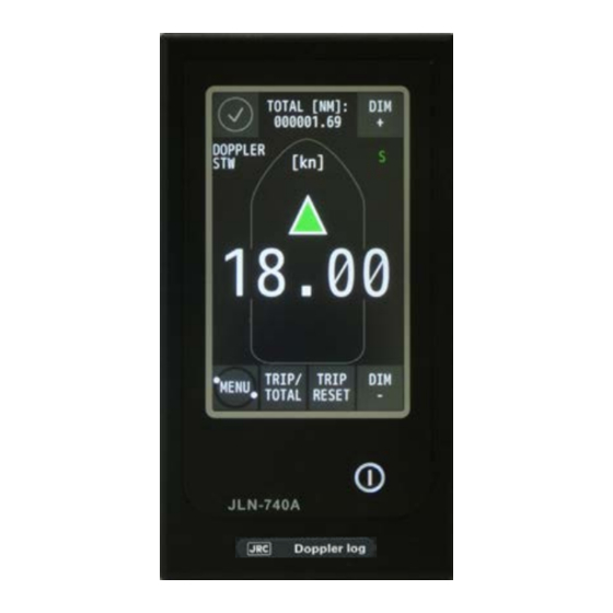
Chapter 2 Function of Each Components 2.1 Main Display NWZ-510SDW (For JLN-740A/741A) Name Function Display • Displays the following information as a display. - Operation status of the equipment (normal/abnormal) - Fore/after speed - Trip distance /total distance • The following operations are enabled on the display. -
Page 56: Main Display Nwz-4640 (For Jln-740N/741N)
2.2 Main Display NWZ-4640 (For JLN-740N/741N) Display Sounder Operation Panel Name Function Use this key to turn on the power. Adjust the contrast. Power/Contrast To turn off the power, press this key together with the Use this key to adjust the brightness of the back light. Dimmer Use this key to display the main menu. -
Page 57: Remote Display (Optional) Nwz-650Sdr/840Sdr
2.3 Remote Display (Optional) NWZ-650SDR/840SDR Remote display NWZ-650SDR (optional) Digital Analog Remote display NWZ-840SDR (optional) Digital Analog Name Function Display • Displays the following information as a display. - Operation status of the equipment (normal/abnormal) - Fore/after speed (in digital or analog) - Trip distance/total distance •... -
Page 58: Mid (Optional) Nwz-4610
2.4 MID (Optional) NWZ-4610 Display Sounder Operation Panel Name Function Use this key to turn on the power. Adjust the contrast. Power/Contrast To turn off the power, press this key together with the Use this key to adjust the brightness of the back light. Dimmer Use this key to display the main menu. -
Page 59: Distance Counter (Optional) Nww-7
2.5 Distance Counter (Optional) NWW-7 Name Function Trip reset Press this key to reset TRIP. Chapter 2 Function of Each Components... - Page 60 (This page intentionally left blank) Chapter 2 Function of Each Components...
-
Page 61: Chapter 3 Operation Method (Jln-740A/741A)
This is normal. If your ship is not on the water such as when it is docked, do not start transmission. Otherwise, the transducer will be damaged. Chapter 3 Operation Method (JLN-740A/741A) -
Page 62: Basic Operation
The power supply is turned on and the start screen is displayed. After about one minute, the START TRANSMIT screen is displayed. Chapter 3 Operation Method (JLN-740A/741A) - Page 63 When the power supply is turned off on the display unit, the equipment then starts when the on-board power supply is turned off/on. This is normal. CAUTION After the blackout test, the system would start up and the START TRANSMIT screen would be displayed. Chapter 3 Operation Method (JLN-740A/741A)
-
Page 64: Adjusting Brightness
[DIM-] button. 17 brightness levels are available. CAUTION Under the minimum brightness, the ship speed display and accumulated sailing distance/trip distance display disappear. Only each corner icons: [ALERT], [DIM+], [DIM-], [MENU] would display. Chapter 3 Operation Method (JLN-740A/741A) -
Page 65: Displaying Ship Speed/Accumulated Sailing Distance
The unit of ship speed can be set to kn or m/s by operating the menu. Ship speed unit For setting the ship speed unit of the main display, refer to “4.1.3.7 Ship Speed Unit Settings”. Chapter 3 Operation Method (JLN-740A/741A) -
Page 66: Displaying The Accumulated Sailing Distance
3.2.2 Displaying the Accumulated Sailing Distance Main Display NWZ-510SDW Chapter 3 Operation Method (JLN-740A/741A) - Page 67 Resetting of the accumulated sailing distance is unable to general users. For resetting the accumulated sailing distance, please request to the store, nearest JRC agent, JRC marine service department, sales department, regional office, branch or sales office. Chapter 3 Operation Method (JLN-740A/741A)
-
Page 68: Displaying Alert
Touch the alert icon for the buzzer sound and touch the displayed alert content to stop (ACK). Every pressing the alert icon, alert content will appear and disappear. Alert icon Alert content When speed through the water cannot be measured, --.-- kn is displayed for the ship speed value. Chapter 3 Operation Method (JLN-740A/741A) - Page 69 The Alert Icons are as follows. Warning occurred Warning silenced Active –acknowledged warning Warning responsibility transfer Rectified –unacknowledged warning Caution When multiple identical alerts occurred simultaneously, check the contents of the alerts with ALERT LIST and ALERT HIST (alert history). Chapter 3 Operation Method (JLN-740A/741A)
- Page 70 At the occurrence of a warning, a buzzer sound is emitted twice followed by an interval of 5 minutes. At the occurrence of a caution, no sound is emitted. Alert colours Warning colour is orange. Caution colour is yellowish orange. Chapter 3 Operation Method (JLN-740A/741A) 3-10...
-
Page 71: Chapter 4 Setting By Using Menus (Jln-740A/741A)
Chapter 4 Setting by Using Menus (JLN-740A/741A) In JLN-740A/741A, various settings and adjustments can be performed by using the menus that are displayed. Adjustments must be made by specialized service technicians. Incorrect settings may result in unstable operation, and this may lead to accidents or equipment failure. -
Page 72: Setting Of Nwz-510Sdw
4.1. Setting of NWZ-510SDW 4.1.1. Main Menu Touch the [MENU] button on the normal screen. [MENU] button Main Display NWZ-510SDW The main menu is displayed. Main menu JLN-740A JLN-741A Main Display NWZ-510SDW Chapter 4 Setting by Using Menus (JLN-740A/741A) - Page 73 [ALERT LIST] (Alert list) Displays the list of current alerts. Displays the history of all alerts that occurred. [ALERT HIST] (Alert history) * JLN-741A does not have the ALERT HIST (JLN-740A only) function. Chapter 4 Setting by Using Menus (JLN-740A/741A)
-
Page 74: Common Operation Of Each Menu
Delete the entered numeric value or character. (Delete) button Enter positive (plus) and negative (minus) as the entered [+/-] (Minus and plus) button numerical value. [10] Enter numbers from 0 to 9 respectively. [0] to [9] (numeric) button Chapter 4 Setting by Using Menus (JLN-740A/741A) -
Page 75: Operation Of Each Menu
Touch the [TOUCH CAL] button in the main menu. A touch position calibration confirmation screen is displayed. Touch [CONFIRM CALIBRATE THE TOUCH SCREEN]. The start screen is displayed. 5 seconds later, a touch position calibration screen is displayed. Chapter 4 Setting by Using Menus (JLN-740A/741A) - Page 76 Perform the adjustment again. Touch the [AGAIN] button and restart from Step 2. CAUTION If the calibration takes about one minute or more, the “DISPLAY COMM FAIL” alert may occur upon returning to the normal screen. This is not the system malfunction. Chapter 4 Setting by Using Menus (JLN-740A/741A)
-
Page 77: Brightness Adjustment
Change the brightness by touching the [-]/[+] buttons. DAY: High brightness (for daytime) (default value) DUSK: Medium brightness (for evening time) NIGHT: Low brightness (for night time) Touch button to apply and close the [THEME] menu. Chapter 4 Setting by Using Menus (JLN-740A/741A) -
Page 78: Date Setting
Set [YEAR], [MONTH], and [DAY] to the actual values by touching the [-]/[+] buttons. The setting ranges are as follows. [YEAR]: 2000 to 2037 (default: 2016) [MONTH]: JAN to DEC (default: JAN) [DAY]: 1 to 31 (default: 1) Chapter 4 Setting by Using Menus (JLN-740A/741A) - Page 79 Set [HOUR] and [MINUTE] to the actual values by touching the [-]/[+] buttons . The setting ranges are as follows. [HOUR]: 0 to 23 (default: 0) [MINUTE]: 0 to 59 (default: 0) Confirm the setting and close the [DATE TIME] menu by touching the button. Chapter 4 Setting by Using Menus (JLN-740A/741A)
-
Page 80: Confirming The System Information
Serial number of the distribution processor. SP ser.: Serial number of the signal processor. Transducer serial number Transducer ser. : (Note: An arbitrary serial number of the transducer must be set at installation.) Chapter 4 Setting by Using Menus (JLN-740A/741A) 4-10... -
Page 81: Advanced Settings Of The Details Of The Equipment At Installation Of This Equipment
A screen for setting the number of decimal digits is displayed. Set the number of decimal digits by touching the [-]/[+] buttons. 2: Displays two decimal digits (default value). 1: Displays one decimal digit. Close the menu by touching the button. 4-11 Chapter 4 Setting by Using Menus (JLN-740A/741A) -
Page 82: Ship Speed Unit Settings
A screen for setting a unit is displayed. Change the unit by touching the [-]/[+] buttons. kn: knot (default value) m/s: meter per second Close the [UNITS] menu by touching the button. Chapter 4 Setting by Using Menus (JLN-740A/741A) 4-12... -
Page 83: Setting The Upper Limit And The Lower Limit For Ship Speed Alerts
When the [-]/[+] button on the screen is touched, each of [UPPER] (upper limit) and [LOWER] (lower limit) decreases/increases. OFF cannot be input with the [-]/[+] button. The [UPPER] cannot be lower than the [LOWER], and the [LOWER] cannot be more than the [UPPER]. 4-13 Chapter 4 Setting by Using Menus (JLN-740A/741A) - Page 84 [UPPER]:-40 to 40, OFF (default: 40) [LOWER]:-40 to 40, OFF (default: -40) When this function is set to OFF, no ship speed alert is issued. Close the menu by touching the button. Chapter 4 Setting by Using Menus (JLN-740A/741A) 4-14...
-
Page 85: Sdme Advanced Settings
When warning is acknowledged while it is occurring, the acknowledgement is displayed. When the list contains multiple pages, the page can be switched by touching the [<]/[>] buttons. Close the [ALERT LIST] menu by touching the button. 4-15 Chapter 4 Setting by Using Menus (JLN-740A/741A) -
Page 86: Alert History
Touch the [ALERT HIST] button in the main menu. An alert list is displayed. When the history covers multiple pages, the page can be switched by touching the [<]/[>] buttons. Close the [ALTER HIST] menu by touching the button. Chapter 4 Setting by Using Menus (JLN-740A/741A) 4-16... -
Page 87: Alert
Alert with main display only. Invalid checksum of NMEA (Talker+ID). INVALID CHECKSUM OF NMEA (Talker+ID) SENTENCE Alert with main display only. (ID) timed out. (ID) TIMED OUT Alert with main display only. 4-17 Chapter 4 Setting by Using Menus (JLN-740A/741A) - Page 88 Alternatively, this warning is issued when there is a possibility for measurement being disabled. CAUTION This caution is issued when the product changed to an unintended state. Note: Some bubble cannot be detected by “Bubble detect function”. Chapter 4 Setting by Using Menus (JLN-740A/741A) 4-18...
-
Page 89: Jln-741A Alert List
Alternatively, this warning is issued when there is a possibility for measurement being disabled. CAUTION This caution is issued when the product changed to an unintended state. Note: Some bubble cannot be detected by “Bubble detect function”. 4-19 Chapter 4 Setting by Using Menus (JLN-740A/741A) -
Page 90: Sentence List That Generates "Id Sentence Abnormal(Parsing Fail)
PJRCM,VD,6 VD,6 PJRCM,VD,8 VD,8 PJRCL,VD,9 VD,9 PJRCM,VD,10 VD,10 PJRCM,VD,17 VD,17 PJRCM,VD,18 VD,18 PJRCM,VD,26 VD,26 PJRCM,VD,39 VD,39 PJRCM,VD,40 VD,40 PJRCM,VD,44 VD,44 PJRCM,VD,50 VD,50 PJRCM,VD,60 VD,60 PJRCM,VD,62 VD,62 PJRCM,VD,80 VD,80 PJRCM,VD,81 VD,81 PJRCM,VD,90 VD,90 Chapter 4 Setting by Using Menus (JLN-740A/741A) 4-20... -
Page 91: Chapter 5 Operation Method (Jln-740N/741N)
Chapter 5 Operation Method (JLN-740N/741N) The Doppler log must be used strictly as navigation aid equipment only. The final decision on navigation must be made by the pilot. If the final decision is made based on the information displayed by the Doppler log only, an accident such as collision or grounding may occur. -
Page 92: Basic Operation
5.1 Basic Operation 5.1.1 Power Supply ON/OFF Power supply button When the main power supply on the power board is turned on, the display unit power supply is turned on automatically. If the power has been turned off by pressing simultaneously, the power can be turned on by pressing The power supply is turned on and the start screen is displayed. - Page 93 When is pressed, the normal screen is displayed. Transmission starts. When are pressed simultaneously, the power supply is turned off and the screen is cleared. CAUTION After the start of the equipment, do not shut down until the START TRANSMIT screen is displayed.
-
Page 94: Adjusting Brightness
5.1.2 Adjusting Brightness Adjust the brightness to the suitable level for display. The brightness of the back light can be changed to any of the four levels, bright, medium, dark, and off by using At the factory shipment, the brightness is set to ‘bright’. Back light button Chapter 5 Operation Method (JLN-740N/741N) -
Page 95: Displaying Ship Speed/Accumulated Sailing Distance
5.2 Displaying Ship Speed/Accumulated Sailing Distance On the normal screen, the fore/after speed and accumulated sailing distance are displayed. 5.2.1 Displaying Ship Speeds Main Display NWZ-4640 Display Remarks When the ship is moving in the ahead direction, ▲ is displayed and Fore/after speed when the ship is moving in the astern direction, ▼... -
Page 96: Displaying The Accumulated Sailing Distance
5.2.2 Displaying the Accumulated Sailing Distance Main Display NWZ-4640 Display/button Remarks Accumulated sailing [Total] displays the accumulated sailing distance. distance (accumulated [Trip] displays the distance of the voyage. sailing distance or trip When the ship departed point A and returned to point A via point distance) B, point C, and point D as shown below, [Trip] is used to calculate the distance of each section. -
Page 97: Displaying Alert
5.3 Displaying Alert The Normal icon is displayed while this equipment is functioning normally. Alert icon When an alert occurs, the alert occurrence is notified by the popup window and a buzzer sound. When is pressed, the popup window and the buzzer sound stops (acknowledged). However, “... - Page 98 (This page intentionally left blank) Chapter 5 Operation Method (JLN-740N/741N)
-
Page 99: Chapter 6 Setting By Using Menus (Jln-740N/741N)
Chapter 6 Setting by Using Menus (JLN-740N/741N) On JLN-740N/741N, various configurations can be set and adjusted by pressing the buttons. Adjustments must be made by specialized service technicians. Incorrect settings may result in unstable operation, and this may lead to accidents or equipment failure. -
Page 100: Setting Nwz-4640
6.1. Setting NWZ-4640 6.1.1. Calling a main menu Press the button. Main Display NWZ-4640 Chapter 6 Setting by Using Menus (JLN-740N/741N) - Page 101 The main menu is displayed. Main Display NWZ-4640 The functions of the main menus of the display unit are as follows. Menu Function Specifies the settings for LCD, click sound, screen selection, and back DISPLAY light color. Changes system settings. SYSTEM System settings can be changed in maintenance mode only.
-
Page 102: Common Operations Of Menus Screens
6.1.2. Common operations of menus screens The following buttons perform the common functions for all the menu screens. (An example of a main menu screen is used for the explanation.) Name Function Adjust the contrast. Power/Contrast To turn off the power, press this key together with the Dimmer Use this key to adjust the brightness of the back light. -
Page 103: Operation Of Each Menu
6.1.3. Operation of each menu 6.1.3.1. Display setting When “DISPLAY” is selected on the main menu, a display menu is displayed. On the display menu, LCD (contrast and back light), click sound, screen selection, and back light colour can be set. Each submenu is outlined below. -
Page 104: Adjusting Back Light
6.1.3.1.2. Adjusting back light • Brightness of the back light can be changed by using . Four levels of brightness are available: bright, medium, dark, and off. This section shows how to set a value of each brightness level. Display a main menu by pressing Select “DISPLAY”, “LCD”, and “DIMMER MAXIMUM/TYPICAL/MINIMUM”... -
Page 105: Setting A Display Screen
6.1.3.1.4. Setting a display screen Up to six display screens can be registered in this display unit. The display screen can be switched either manually by using or automatically (auto screen function). The auto screen function enables the setting of a switching interval. Switching can also be notified by emitting a sounder. -
Page 106: Step1 Selecting A Display Screen
6.1.3.1.4.1. STEP1 Selecting a display screen Up to six display screens can be registered in this display unit. DISPLAY1 DISPLAY2 DISPLAY3 DISPLAY4 DISPLAY5 or automatic DISPLAY6 Display a main menu by pressing (normal mode). Select “DISPLAY” and “DISPLAY SELECT” in that order by using and press Select a display screen from “DISPLAY1”... -
Page 107: Step2 Selecting A Screen Structure
6.1.3.1.4.2. STEP2 Selecting a screen structure The screen structures of each display screen include customised screens that can be set freely, special screens that do not allow any setting, and graphic screens. Select a screen structure. When display structure selection is set to “OFF”, the display screen cannot be registered. Customised screen One screen can be segmented into screens 1 to 4. - Page 108 Select a display screen by referencing “STEP1”. Select a screen structure from “SEGMENTATIOIN1”, “SEGMENTATION2”, “SEGMENTATION3, “SEGMENTATION4”, “SPECIAL”, “GRAPHIC” and ‘OFF” by using and press Select SEGMENTATION1, SEGMENTATION2, SEGMENTATION3, SEGMENTATION4, SPECIAL, GRAPHIC, OFF. Chapter 6 Setting by Using Menus (JLN-740N/741N) 6-10...
-
Page 109: Step3 Selecting Display Contents
6.1.3.1.4.3. STEP3 Selecting display contents Select as many display contents as the number of screens that are created by segmentation. For instance, for a 2-segmentation screen, select the display content for one half of the screen and then select the display content for the other half of the screen (see the diagram below). First select Doppler on the customised screen, and, next, select the display contents. - Page 110 Select a screen structure by referencing “STEP1” and “STEP2”. Customized screen Select a screen section to be displayed by using and press Select the screen section from the following: 1-segmentation screen: “DISPLAY’ 2-segmentation screen: “DISPLAY 1/2” “DISPLAY 2/2” 3-segmentation screen: “DISPLAY 1/3” “DISPLAY 2/3” “DISPLAY 3/3” 4-segmentation screen: “DISPLAY 1/4”...
- Page 111 Display structure and display contents Display structure Display Display contents Segmentation 1, 2, 3, 4 DOPPLER/OFF Fore/after STW, TRIP, ODO(Odometer) Special screen STW 1/2/3 Graphic screen STW ship speed Setting an auto screen On an auto screen, set a screen switching time and whether a sounder is emitted at screen switching. Select “ON”...
-
Page 112: Select A Back Light Color
Auto range Integer part expanded Integer part expanded Display contents Normal display display (special 1) display (special 2) 10.0kn or more 1.0 to 9.9kn 0.9kn or less Accumulated sailing 10.00NM or more 1.00 to9.99NM 0.99NM or less distance/trip distance Set the display contents by using the procedure described above. Select “DISPLAY MODE”... -
Page 113: System Setting
6.2. System setting Users can check the speed unit, smoothing time and digit of speed. To select the speed unit, press to alternate “kn” and “m/s”. (see 5.2.1) If you need to change other system settings, enter the service engineer menu. (see 6.10) 6.3. -
Page 114: Sensor Setting
6.5. Sensor setting Users can check the speed correction rate, NMEA setting, speed pulse output and analog meter full scale. If you need to change sensor settings, enter the service engineer menu. (see 6.10) speed correction rate is displayed. On JLN-741N sensor setting menu, only 6.6. -
Page 115: Alert List Display
6.8. Alert list display The alert that is currently occurring and not yet ACK and unresolved is displayed until it is ACKed and restored. (A total of 40 items will be displayed.) In the JLN - 740N, 8. alert list is displayed, in JLN - 741N, 7. alert list is displayed. JLN-740N Alert list display example For the displayed contents, see section 6.9.5. -
Page 116: Alerts That Occur In Jln-741N
6.9.1 Alerts that occur in JLN-741N Alert message WARNING CAUTION Possible Cause Deterioration of received signal level or Ship speed lost STW increase of noise. Foam is formed on the surface of the transducer mounting. HW error display Main display hardware error ... - Page 117 6.9.2 Alerts that occur in JLN-741N Alert message WARNING CAUTION Possible Cause Deterioration of received signal level or Ship speed lost STW increase of noise. Foam is formed on the surface of the transducer mounting. Speed exceeded the limit STW exceeded the speed setting range.
-
Page 118: Sentence List That Generates "Id Sentence Abnormal(Parsing Fail)
6.9.3 Sentence list that generates “ID sentence abnormal(PARSING FAIL)” Sentence Wording of "ID" part PJRCM,VD,4 VD,4 PJRCM,VD,6 VD,6 PJRCM,VD,8 VD,8 PJRCL,VD,9 VD,9 PJRCM,VD,10 VD,10 PJRCM,VD,17 VD,17 PJRCM,VD,18 VD,18 PJRCM,VD,26 VD,26 PJRCM,VD,39 VD,39 PJRCM,VD,40 VD,40 PJRCM,VD,44 VD,44 PJRCM,VD,50 VD,50 PJRCM,VD,60 VD,60 PJRCM,VD,62 VD,62 PJRCM,VD,80... -
Page 119: Display Of Alert List · History Screen
6.9.4 Display of alert list · history screen On the alert history screen, an example of warning display (JLN-740N) Active warning [ HW ERR (NQA-7040) ]→ ACK → Rectified It is lining up so that new alert history is above. In JLN - 741N, the date and time of occurrence, ID is blank. -
Page 120: Installation Setting
6.10. Installation setting Maintenance menu includes system settings of JLN-740N / 741N. CAUTION Never change anything other than those described in this chapter. Changing it may cause malfunction or failure. Display a main menu by pressing the button. (normal menu) When are press and hold for 3 seconds (shift to Equipment Mode). -
Page 121: Language Setting
6.10.2 Language setting 3. In Maintenance mode of language setting, [ENGLISH] · [JAPANESE] can be switched. 6.10.3 Sensor setting 5. In the sensor setting mode of sensor setting, you can set the boat speed correction value, serial output setting, pulse output setting, and scale setting of the analog meter. Please do not change usually because it is related to equipment operation. - Page 122 (This page intentionally left blank) Chapter 6 Setting by Using Menus (JLN-740N/741N) 6-24...
-
Page 123: Chapter 7 Operation Method (Option)
Chapter 7 Operation Method (Option) The Doppler log must be used strictly as navigation aid equipment only. The final decision on navigation must be made by the pilot. If the final decision is made based on the information displayed by the Doppler log only, an accident such as collision or grounding may occur. -
Page 124: Basic Operation
7.1 Basic Operation 7.1.1 Adjusting Brightness Adjust the brightness to the suitable level for display. Adjust the brightness by touching the [DIM+] button/[DIM-] button on the display. The brightness is set to maximum initially. [DIM+] button [DIM-] button Remote Display NWZ-650SDR (Optional) [DIM+] button [DIM-] button Remote Display NWZ-840SDR (Optional) - Page 125 Lighting key Multi-information Display NWZ-4610 (Optional) The brightness of the backlight can be adjusted to four levels, DAY, DUSK, NIGHT, and OFF by pressing At the factory shipment, the brightness is set to DAY. Chapter 7. Operation Method (Option)
-
Page 126: Displaying Ship Speed/Accumulated Sailing Distance
7.2 Displaying Ship Speed/Accumulated Sailing Distance On the normal screen, the fore/after speed and accumulated sailing distance are displayed. 7.2.1 Displaying Ship Speeds Remote Display NWZ-650SDR (Optional) Remote Display NWZ-840SDR (Optional) Multi-information Display NWZ-4610 (Optional) Display Remarks When the ship is moving in the ahead direction, is displayed and Fore/after speed when the ship is moving in the astern direction, ... -
Page 127: Displaying The Accumulated Sailing Distance
7.2.2 Displaying the Accumulated Sailing Distance Remote Display NWZ-650SDR (Optional) Remote Display NWZ-840SDR (Optional) Distance Counter NWW-7 (Optional) Chapter 7. Operation Method (Option) - Page 128 Display/button Remarks Sailing distance Whenever the [TRIP/TOTAL] button is touched, the display (accumulated sailing changes between the total sailing distance and section sailing distance or trip distance) distance. As shown below, when a ship leaves point A, stopover at points B, C, and D, then goes back to point A, the [TRIP] (trip distance) is used to calculate the distance of each of the individual segments between the point.
- Page 129 Multi-information Display NWZ-4610 (Optional) Display/button Remarks Sailing distance [Total] displays the accumulated sailing distance. (accumulated sailing [ODO] displays the distance of the voyage. distance or trip distance) As shown below, when a ship leaves point A, stopover at points B, C, and D, then goes back to point A, the [ODO] (trip distance) is used to calculate the distance of each of the individual segments between the point.
-
Page 130: Displaying Alert
Normal icon Remote Display NWZ-650SDR (Optional) Normal icon Remote Display NWZ-840SDR (Optional) For the occurrence of alert, refer to “3.3 Alert display” (JLN-740A/741A) or “5.3 Alert display” (JLN-740N/JLN-741N). Resetting trip distance, refer to NWZ-4610 instruction manual. Chapter 7 Operation Method (Option) -
Page 131: Chapter 8 Setting By Using Menus (Option)
Chapter 8 Setting by Using Menus (Option) In NWZ-650SDR/840SDR, various settings and adjustments can be performed by using the menus that are displayed. On NWZ-4610, various configurations can be set and adjusted by pressing the buttons. Adjustments must be made by specialized service technicians. Incorrect settings may result in unstable operation, and this may lead to accidents or equipment failure. -
Page 132: Setting Of Nwz-650Sdr/840Sdr
8.1. Setting of NWZ-650SDR/840SDR 8.1.1. Main Menu Touch the [MENU] button on the normal screen. [MENU] button Remote Display NWZ-650SDR (Optional) [MENU] button Remote Display NWZ-840SDR (Optional) Chapter 8 Setting by Using Menus (Option) - Page 133 The main menu is displayed. Main menu Remote Display NWZ-650SDR (Optional) Main menu Remote Display NWZ-840SDR (Optional) The functions of sub-display menus are as follows. Menu Function [TOUCH CAL] (Touch position calibration) Adjusts the shift of the display position. [DISP MODE] (Display mode selecting) Selecting the display mode of remote display.
-
Page 134: Operation Of Each Menu
8.1.2. Operation of Each Menu 8.1.2.1. Touch Position Calibration When the touched position and the intended button do not match when the screen is touched, adjust the touched position in this menu. Touch the [TOUCH CAL] button in the main menu. A touch position calibration confirmation screen is displayed. -
Page 135: Brightness Adjustment
8.1.2.2. Brightness Adjustment The brightness of the screen can be adjusted by the time period of a day. Touch the [THEME] button in the main menu. A brightness adjustment screen is displayed. Change the brightness by touching the [-]/[+] buttons. DAY: High brightness (for daytime) (initial value) DUSK: Medium brightness (for evening time) NIGHT: Low brightness (for night time) -
Page 136: Date Setting
8.1.2.3. Date Setting Information on the date and time of the remote display can be set in this menu according to the actual information. Touch the [DATE TIME] button in the main menu of remote display. Set [YEAR], [MONTH], and [DAY] to the actual values by touching the [-]/[+] buttons. The setting ranges are as follows. - Page 137 Set [HOUR], [MINUTE] and [TIME ZONE] to the actual values by touching the [-]/[+] buttons. The setting ranges are as follows. [HOUR]: 0 to 23 (initial value: 0) [MINUTE]: 0 to 59 (initial value: 0) [TIME ZONE]: -12:00 to +12:00 (initial value: 00:00) Confirm the setting and close the [DATE TIME] menu by touching the button.
-
Page 138: Confirming The System Information
8.1.2.4. Confirming the system information The information relating to this equipment such as software version can be displayed. Before making an enquiry on this equipment, check the information of this equipment in the [ABOUT] menu. Touch the [ABOUT] button in the main menu. Information on the equipment is displayed. -
Page 139: Advanced Settings Of The Details Of The Equipment At Installation Of This Equipment
8.1.2.5. Advanced Settings of the details of the equipment at installation of this equipment Touch the [ADV SET] button on the main menu. A password input screen is displayed. This menu is intended for engineers who are to install this equipment. This menu is not for general users. -
Page 140: Ship Speed Unit Settings
8.1.2.7. Ship Speed Unit Settings The unit of the ship speed that is displayed on the normal screen can be set. Touch the [UNITS] button in the main menu. A screen for setting a unit is displayed. Change the unit by touching the [-]/[+] buttons. kn: knot (initial value) m/s: meter per second Close the [UNITS] menu by touching the... - Page 141 8.1.2.8. Advanced SDME Settings Touch the [ADV SDME] button on the main menu. A password input screen is displayed. This menu is intended for engineers who are to install this equipment. This menu is not for general users. 8-11 Chapter 8 Setting by Using Menus (Option)
-
Page 142: Sog And Stw Selection
8.1.2.9. SOG and STW selection The speed over the ground and the speed through the water of the remote display can be selected. Touch the [SOG/STW] button in the main menu of remote display. SOG/STW setting screen is then displayed. Touch the [-]/[+] buttons to switch the SOG and STW of the remote display GNSS SOG: Speed over the group by the satellite log (initial value) DOPPLER SOG: Display the ship speed over the ground from the Doppler. -
Page 143: Chapter 9 Installation Method
Chapter 9 Installation Method Electrical work for this equipment must be requested to the store, nearest JRC agent, JRC marine service department, sales department, regional office, branch or sales office. Conducting electrical work by anyone other than the specialized maintenance staff may result in an accident or an equipment fault. Use the screws that are specified in the installation manual when installing this equipment. -
Page 144: Installation Of The Main Display And Distribution Processor
9.1 Installation of the Main Display and Distribution Processor Installation location Install these equipment units in a place that is not susceptible to interferences since signal cables are susceptible to noise and generate noise easily. Do not install the equipment units parallel to the cable of the DSB radio or amateur radio device. Do not install the equipment units in a place that is exposed to direct sunlight (except wing displays), wave splashes, or hot air. -
Page 145: Installation Of The Transducer Mounting
9.2 Installation of the Transducer Mounting CAUTION It is necessary to choose the place where the bubble is not generated when sailing, and to install the transducer mounting. The transducer mounting is installed in place before 1/10 of the ship’s lengths in the large vessel. Moreover, the transducer mounting is installed in place before it when there is bow-thruster. -
Page 146: Connection Diagram
9.3 Connection Diagram For details of the equipment connection, refer to the Installation Manual. 9.3.1 JLN-740A inter-connection diagram Chapter 9 Installation Method... -
Page 147: Jln-740N Inter-Connection Diagram
9.3.2 JLN-740N inter-connection diagram Chapter 9 Installation Method... -
Page 148: Jln-741A Inter-Connection Diagram
9.3.3 JLN-741A inter-connection diagram Chapter 9 Installation Method... -
Page 149: Jln-741N Inter-Connection Diagram
9.3.4 JLN-741N inter-connection diagram Chapter 9 Installation Method... - Page 150 (This page intentionally left blank) Chapter 9 Installation Method...
-
Page 151: Chapter 10 Maintenance And Inspection
Chapter 10 Maintenance and Inspection Customers shall never attempt to check or repair the inner of the equipment. Inspection or repair by anyone other than the specialized maintenance staff may result in fire or electric shock. For maintenance, inspection of the internal section of the equipment, request the store, nearest JRC agent, JRC marine service department, sales department, regional office, branch or sales office. -
Page 152: Countermeasures For Abnormalities And Faults
10.2 Countermeasures for Abnormalities and Faults When any of the following symptoms is detected, contact the store, nearest JRC agent, JRC marine service department, sales department, regional office, branch or sales office. • The screen is blank or the power is not supplied to the equipment even if the power supply button is pressed. -
Page 153: Troubleshooting
10.4 Troubleshooting JLN- JLN- JLN- JLN- Fault symptom Assumed cause Countermeasure 740A 740N 741A 741N The power supply is Power is not supplied Check if the wiring not turned on even if from the on-board from the distribution the power switch is distribution board. - Page 154 JLN- JLN- JLN- JLN- Fault symptom Assumed cause Countermeasure 740A 740N 741A 741N The ship speed that is The ship speed Contact JRC Sales displayed is obviously correction setting is Department, or your slow. incorrect. nearest branch, sales ...
- Page 155 JLN- JLN- JLN- JLN- Fault symptom Assumed cause Countermeasure 740A 740N 741A 741N Alert “OVER SPEED Ship speed through Check the speed limit STW” is displayed. water exceeded the setting. (Refer to speed limit setting 4.1.3.8 and 6.1.3.4.) range.
- Page 156 (This page intentionally left blank) Chapter 10 Maintenance and Inspection 10-6...
-
Page 157: Chapter 11 After-Sales Service
Chapter 11 After-Sales Service 11.1 Requesting Repair When suspecting “fault”, stop using the equipment and contact the store, nearest JRC agent, JRC marine service department, sales department, regional office, branch or sales office. Repair under the warranty period When the equipment becomes faulty while it is used in the normal utilization condition according to the description/instruction in the instruction manual, the distributor or JRC will repair the equipment without charge. -
Page 158: Recommendation Of Inspection And Maintenance
11.2 Recommendation of Inspection and Maintenance The performance may deteriorate due to the aging of parts although the degree varies depending on the utilization condition. For the inspection and maintenance separate from the normal maintenance, contact the store, nearest JRC agent, JRC marine service department, sales department, regional office, branch or sales office. -
Page 159: Chapter 12 Disposal
Chapter 12 Disposal Disposal treatment of this equipment must comply with the rules and regulations of the Government or the local government. Disposal of this equipment Disposal treatment of this equipment must comply with the regulations or rules of the Government or the local government that controls the location of the disposal. - Page 160 (This page intentionally left blank) Chapter 12 Disposal 12-2...
-
Page 161: Chapter 13 Specification
Chapter 13 Specification 13.1. General Specification 13.1.1. JLN-740A Water speed measuring system Dual – beam pulse Doppler system Operation frequency 2 MHz Fore/after speed measurement scale -10.00 to +40.00 kn No. of digits displayed Fixed 4 or 3 digits selectable Minimum digital display unit 0.01 kn or 0.1 kn selectable... -
Page 162: Jln-741A
13.1.3. JLN-741A Water speed measuring system Dual – beam pulse Doppler system Operation frequency 2 MHz Fore/after speed measurement scale -10.00 to +40.00 kn No. of digits displayed Fixed 4 or 3 digits selectable Minimum digital display unit 0.01 kn or 0.1 kn selectable Sailing display range 0 to 999999.99NM Water speed measurable depth... -
Page 163: Display Unit
13.2. JLN-740A/741A Main Display NWZ-510SDW CAUTION JLN-741A/741N does not use NWZ-510SDW 13.2.1. Display Unit Display unit 5-inch color LCD, 480(H) × 800(V) pixels (WVGA) Pixel pitch 0.135 mm Operation buttons Touch panel and power supply button Backlight (LED) LCD and power supply button... -
Page 164: External Interface
13.2.5. External Interface [JLN-741A configuration] IEC 61162-1 Output: 2ch Chapter 13 Specification 13-4... -
Page 165: Jln-740N/741N Main Display Nwz-4640
13.3. JLN-740N/741N Main Display NWZ-4640 CAUTION JLN-741A/741N does not use NWZ-4640 13.3.1. Display Unit Display unit 4.5 inch monochrome LCD 128 × 64 dots Pixel pitch 0.74 mm Backlight White LED or orange LED (selectable) Dimmer Levels 4 levels (Bright, Medium, Dark, OFF) Dimmer control Key or external dimmer unit Contrast... -
Page 166: Distribution Processor Nqa-7040
13.4. Distribution Processor NQA-7040 CAUTION JLN-741A/741N does not use NQA-7040 13.4.1. Electrical Specifications Power supply voltage 100/230VAC (90V to 253V) Power consumption Maximum 30 W (include sensor and displays power) 13.4.2. Environmental Requirements Operating temperature range -15°C to +55°C (IEC 60945 ed.4 Protected equipment) Storage temperature range -20°C to +70°C Protection level... -
Page 167: Signal Processor Njc-70S
13.5. Signal Processor NJC-70S 13.5.1. Electrical Specifications Power supply voltage 100/230VAC (90V to 253V) Power consumption Maximum of 19 W 13.5.2. Environmental Requirements Operating temperature range -15°C to +55°C (IEC 60945 ed.4 Protected equipment) Storage temperature range -20°C to +70°C Protection level IP55 Vibration... -
Page 168: Transducer Mounting Nkf-547
13.6. Transducer mounting NKF-547 13.6.1. Electrical Specifications Operation frequency 2 MHz Oscillator CFT-022C 13.6.2. Environmental Requirements Operating temperature range -3°C to +40°C Storage temperature range -10°C to +70°C Transducer mounting water pressure resistance 600 kPa (6 bar) for 12 h 13.6.3. -
Page 169: Electrical Specifications
13.7. Transducer mounting (Option) NKF-531E 13.7.1. Electrical Specifications Operation frequency 2 MHz Oscillator CFT-023C 13.7.2. Environmental Requirements Operating temperature range -3°C to +40°C Storage temperature range -10°C to +70°C Transducer mounting water pressure resistance 600 kPa (6 bar) for 12 h 13.7.3. -
Page 170: Display Unit
13.8. Remote Display (Optional) NWZ-650SDR CAUTION JLN-741A/741N does not use NWZ-650SDR 13.8.1. Display Unit Display unit 6.5-inch color LCD, 480(H) × 640(V) pixels (VGA) Pixel pitch 0.207 mm Operation buttons Touch panel and power supply button Backlight (LED) LCD and power supply button Maximum luminance 300 cd/m or more (Default brightness value is ‘Maximum Dim+... -
Page 171: Display Unit
13.9. Remote Display (Optional) NWZ-840SDR CAUTION JLN-741A/741N does not use NWZ-840SDR 13.9.1. Display Unit Display unit 8.4-inch color LCD, 800(H) × 600(V) pixels (SVGA) Pixel pitch 0.213 mm Operation buttons Touch panel and power supply button Backlight (LED) LCD and power supply button or more (Default brightness value is ‘Maximum Dim+ Maximum luminance 300 cd/m... -
Page 172: Display Unit
13.10. MID (Optional) NWZ-4610 CAUTION JLN-741A/741N does not use NWZ-4610 13.10.1. Display Unit Display unit 4.5-inch black-and-white LCD, 128 × 64 pixels Pixel pitch 0.74 mm Backlight White LED or Orange LED (switched by setting) Dimmer function adjustments 4-level (bright, intermediate, dark, off) Dimmer control Button or dimmer unit Contrast... -
Page 173: Iec 61162-1 Input/Output Data
13.11. JLN-740A/N Data Format 13.11.1. IEC 61162-1 Input/Output Data Output data 13.11.1.1. Protocol IEC 61162-1(NMEA0183) Baud rate : 4800 Data bit : 8 bits Parity : none Start bit Stop bit interval : 1 sec version : NMEA0183 ver1.5, 2.1, 2.3, 4.0, IEC 61162-1 version is selected by installation setting menu. - Page 174 Output data format ■ VBW – Dual ground/water speed Version 1.5 $VDVBW, uxx.xx,uxx.xx,A,uxx.xx,uxx.xx,A<CR><LF> Version 2.1 $VDVBW, x.x,x.x,A,x.x,x.x,A *hh<CR><LF> 2 3 4 5 6 11 Version 2.3, 4.0, IEC 61162-1 $VDVBW, x.x,x.x,A,x.x,x.x,A,x.x,A,x.x,A*hh<CR><LF> 2 3 4 5 6 7 8 9 10 11 : Fore/after speed over water, knots “-“...
- Page 175 ■ ALR – Set alarm state $VDALR, hhmmss.ss, xxx, A, A, c-c *hh<CR><LF> 2 3 4 5 6 : Time of alarm condition change, UTC : Unique alarm number (identifier) at alarm source : Alarm condition (A = threshold exceeded, V = not exceeded) : Alarm’s acknowledge state, A = acknowledged, V = unacknowledged : Alarm’s description text...
-
Page 176: Input Data
■ ARC – Alert command refused $ VDARC, hhmnss.ss, aaa, x.x, x.x, c*hh<CR><LF> : Release time : Alert specifically defined by the manufacturer : Alert ID : Alert instance : Rejected alert command : Checksum ■ HBT – Monitoring communication enabled/disabled $ VDHBT, x.x, A, x*hh<CR><LF>... - Page 177 Serial Alarm 1 port ACK : Acknowledge alarm ACN : Alert command HBT : Monitoring communication enabled/disabled Dimmer Serial 1 port DDC : Display dimming control Input data format ■ RMC – Recommended minimum specific GNSS data $--RMC,hhmmss.ss,A,llll.ll,a,yyyyy.yy,a,x.x,x.x,xxxxxx,x.x,a,a,a*hh<CR><LF> 9 10 11 : UTC clock time : Status A=Valid V=Invalid : Latitude, N/S...
- Page 178 ■ ACK – Acknowledge alarm $--ACK, xxx*hh<CR><LF> :Alarm number :Checksum ■ ACN (Alarm command) $--ACN,hhmmss.ss,aaa,x.x,x.x,c,a*hh <CR><LF> 4 5 6 7 : Time : Manufacturer mnemonic code : Alert Identifier : Alert Instance, 1 to 999999 : Alert command, A, Q, O or S : Sentence status flag : Checksum ■...
-
Page 179: Iec 61162-450 I/F
13.11.2. IEC 61162-450 I/F IP Address 172.16.60.124 Subnet mask 255.255.255.0 Transmission group NAVD (239.192.0.4:60004 UDP) Sentence I/O $VDVBW $VDVLW $VDDDC In/Out (Receiving DDC is not always VD.) $VDALF $VDALC $VDARC $--ACN $VDHBT In/Out (Receiving HBT is not always VD.) $--RMC $--ZDA 13-19 Chapter 13 Specification... -
Page 180: Jln-741A/N Data Format
13.12. JLN-741A/N Data Format 13.12.1. IEC 61162-1 Output Data 13.12.1.1. Output data Protocol IEC 61162-1(NMEA0183) Baud rate : 4800 Data bit : 8 bits Parity : none Start bit Stop bit interval : 1 sec : NMEA0183 ver1.5, 2.1, 2.3, 4.0, IEC 61162-1 version version is selected by installation setting menu. - Page 181 Output data format ■ VBW – Dual ground/water speed Version 1.5 No VBW sentence output Version 2.1 $VDVBW, x.x,x.x,A,x.x,x.x,A *hh<CR><LF> 2 3 4 5 6 11 Version 2.3, 4.0, IEC 61162-1 $VDVBW, x.x,x.x,A,x.x,x.x,A,x.x,A,x.x,A*hh<CR><LF> 2 3 4 5 6 7 8 9 10 11 : Fore/after speed over water, knots “-“...
-
Page 182: About Chinese Version Rohs
13.13. About Chinese version RoHS 有害物质的名称及含量 (Names & Content of hazardous substances) 形式名 名称 : JLN-740A/740N/741A/741N (Type) : Doppler Log (Name) 有害物质 (Hazardous Substances) 部件名称 (Part name) 铅 汞 镉 六价铬 多溴联苯 多溴二苯醚 (Pb) (Hg) (Cd) (Cr(Ⅵ)) (PBB) (PBDE) 室外装置... -
Page 183: Appendix A Menu List
MINUTE 0 to 59 Minute Version of main Display ver.: NWZ-510SDW display Version of distribution DP Proc .ver.: NQA-7040 processor JLN-740A only) Signal processor SP Ctrl ver.: NJC-70S control version Signal processor SP Calc ver.: NJC-70S computation version Signal processor SP FPGA ver.:... - Page 184 User settings Connected Menu item Setting name Setting value Description equipment Current Change ETHERNET,UART 0,UART CENTRL DIM INPUT UART 2,UART (CENTRAL DIMMER) 3,ANY,NONE Setting of IP IP ADDRESS address ETH CONFIG Each device Setting of subnet (ETHERNET) SUBNET MASK mask GATEWAY Setting of gateway UART 0,UART 1,UART...
- Page 185 ON,OFF Setting of 18kn test SETTI SYSTEM NGS) TEST[1/2] LOST ALERT ON,OFF Setting of alert test Main NW2 HW ON,OFF JLN-740A only display TEST ALERT SYSTEM TEST[2/2] NQA HW ALERT ON,OFF JLN-740A only NJC HW ALERT ON,OFF JLN-740A only TRAN-SMIT...
- Page 186 Display reset list Main display(NWZ-510SDW) ADV SET Menu item Setting name Setting value RESET TOUCH SCREEN TOUCH CAL (TOUCH SCREEN CALIBRATION) CALIBRATION THEME ILLUMINATION DAY,DUSK,NIGHT YEAR 2000 to 2037 JAN,FEB,MAR,APR, DATE TIME MONTH MAY,JUN,JUL,AUG, (DATE/TIME[1/2]) SEP,OCT,NOV,DEC End of 1 to MONTH HOUR 0 to 23 (DATE/TIME[2/2])
- Page 187 Remote display (NWZ-650SDR, NWZ-840SDR) ADV SET Menu item Setting name Setting value RESET TOUCH SCREEN TOUCH CAL (TOUCH SCREEN CALIBRATION) CALIBRATION THEME ILLUMINATION DAY,DUSK,NIGHT YEAR 2000 to 2099 JAN,FEB,MAR,APR, DATE TIME MONTH MAY,JUN,JUL,AUG, (DATE/TIME[1/2]) SEP,OCT,NOV,DEC End of 1 to MONTH HOUR 0 to 23 (DATE/TIME[2/2])
-
Page 188: Display Menu List (Nwz-4640
A.2 Display menu list (NWZ-4640) Main menu Submenu Range Remarks 1. LCD 1. DISPLAY 1. CONTRAST 1,2,3,4,5,6,7,8,9,10,11,12,13 2. DIMMER MAXIMUM 4,5,6,7,8,9,10,11,12,13 3. DIMMER TYPICAL 3,4,5,6,7,8,9,10,11,12 2,3,4,5,6,7,8,9,10,11 4. DIMMER MINIMUM 2. CLICK SOUND ON / OFF 3. DISPLAY SELECTION 1. DISPLAY1 OFF/SEG.1/2/3/4/SPECIAL/GRA. - Page 189 2. SYSTEM 1. UNIT ADMIN( MAINTENACE 1. SPEED kn / m/s ) MODE 2. SMOOTHING ADMIN( MAINTENACE 10-240sec 1. STW ) MODE ADMIN( MAINTENACE 3. SPEED DEC. NUM ) MODE ADMIN( MAINTENACE 3. LANG. 1. LANG. English /(Japanese) ) MODE 4.
- Page 190 Maintenance menu ___: Do not change this section. Main menu Submenu Range Remarks From 1 to 6 is same as Normal MENU 7. INTERFACE 1. DATA I/O 1. DATA IN/OUT1 NMEA Change prohibited Change prohibited 1. DATA IN/OUT SEND/RECEIVE 1. VERSION 1.5/2.1/2.3/4.0 Transmission only SENTENCE...
- Page 191 8.MAINTENANCE 1. INPUT DATA 2. DIAGNOSIS 1. DISPLAY DIAG 2. MONITOR TEST 3. BUZZER TEST 3. ERROR LOG 1. ALERT 2. ERROR LOG 4. SOFT VERSION 1. DISPLAY VER 1. APP VER 2. SERIAL NUMBER 3. BARCODE ON/OFF 5. TX 9.
-
Page 192: Maintenance Software Menu List
A.3 Maintenance software menu list JLN-740A, JLN-740N Set value of the underline is the value of the factory. User settings Menu item Item name Setting name Setting value Description Current Change VD4 Start Measure Measure Stopped, Started Start of transmission... - Page 193 User settings Menu item Item name Setting name Setting value Description Current Change VD1 Main Display Display(NWZ-510SD 0 to 9999 Total operation time (Main display-Day) only W/NWZ-4640) Status Display 0 to 23 Total operation time (Main display-Hour) only Display 0 to 59 Total operation time (Main display-Minute) only Normal :...
- Page 194 User settings Menu item Item name Setting name Setting value Description Current Change Normal : Green Display Lost Speed Lost speed alert (fore/after) Abnormal : only Normal : Lost Transverse Green Display Lost speed alert (port/starboard) Speed Abnormal : only Normal : Green Display...
- Page 195 User settings Menu item Item name Setting name Setting value Description Current Change Enabled : Red LOST SPEED System test (Lost speed alert) Disabled : Green Main Display Enabled : Red System test (Main display hardware error) HW ERROR Disabled : Green VD18 System Test Distribution Enabled : Red...
- Page 196 User settings Menu item Item name Setting name Setting value Description Current Change Normal : Green Display PA Error(3) PA3 error Abnormal : only Normal : Green Display PA Error(4) PA4 error Abnormal : only Normal : Green Display RSLT Error(1) RSLT1 error Abnormal : only...
- Page 197 User settings Menu item Item name Setting name Setting value Description Current Change Normal : Software Green Display Software version abnormality (computation Version Abnormal : only CPU1) Normal : Software Green Display Software version abnormality (computation Version Abnormal : only CPU2) Normal : Software...
- Page 198 User settings Menu item Item name Setting name Setting value Description Current Change 0.0.0.0 to 172.16.0.2 to IP Address IP address 255.255.255.255 VD42 Ethernet 0.0.0.0 to 255.255.0.0 to Subnet Mask Subnet mask Configuration For Main 255.255.255.255 Display Port 00:00:00:00:00:00 to MAC Address 00:00:27:00:00:02 to MAC address...
- Page 199 User settings Menu item Item name Setting name Setting value Description Current Change DDC Talker Disable,Enable Talker filter Enable flag Filter VD48 Brightness Talker Filter AA to VD to ZZ Talker Control Configuration SFI number(For 0000 to 9999 SFI number Ethernet Date-Time Auto Static Date-Time Input,Use...
- Page 200 User settings Menu item Item name Setting name Setting value Description Current Change MISC(239.192.0.1: 60001), TGTD(239.192.0.2: 60002), SATD(239.192.0.3: 60003), NAVD(239.192.0.4: 60004), VDRD(239.192.0.5: 60005), RCOM(239.192.0.6: 60006), TIME(239.192.0.7: 60007), Transmission PROP(239.192.0.8: 60008), Multicast group for IEC 61162-450 Group(for HBT) USR1(239.192.0.9: 60009), reception (HBT) USR2(239.192.0.10: 600010), USR3(239.192.0.11: 600011), USR4(239.192.0.12: 600012),...
- Page 201 User settings Menu item Item name Setting name Setting value Description Current Change MISC(239.192.0.1: 60001), TGTD(239.192.0.2: 60002), SATD(239.192.0.3: 60003), NAVD(239.192.0.4: 60004), VDRD(239.192.0.5: 60005), RCOM(239.192.0.6: 60006), TIME(239.192.0.7: 60007), Transmission PROP(239.192.0.8: 60008), Multicast group for IEC61162-450 Group(for ZDA) USR1(239.192.0.9: 60009), reception (ZDA) USR2(239.192.0.10: 600010), USR3(239.192.0.11: 600011), USR4(239.192.0.12: 600012),...
- Page 202 User settings Menu item Item name Setting name Setting value Description Current Change Number of IEC 61162-450 tab block 4th from left 0 to 128 Display only check sum errors (maintenance) Number of IEC 61162-450 sentence 5th from left 0 to 128 Display only syntax errors (maintenance) Number of IEC 61162-450 sentence...
- Page 203 JLN-741A, JLN-741N Set value of the underline is the value of the factory. User settings Menu item Item name Setting name Setting value Description Current Change VD4 Start Measure Measure Started,Stopped Start of transmission VD6 Speed Calculation Speed -50.0 to 0.0 to 50.0 Correction of ship speed Configuration Correlation...
- Page 204 User settings Menu item Item name Setting name Setting value Description Current Change Ch2: 0 to 4096 Display only Travelling wave (Ch2: After direction) VD19 Power Detect Travelling wave (Ch3: Starboard Ch3: 0 to 4096 Display only Value direction) Ch4: 0 to 4096 Display only Travelling wave (Ch4: Port direction)
- Page 205 User settings Menu item Item name Setting name Setting value Description Current Change Channel 1 Disable,Enabled Channel 1 valid flag Channel 2 Disable,Enabled Channel 2 valid flag VD59 Channel Enable Flag All Settings Channel 3 Disable,Enabled Channel 3 valid flag Channel 4 Disable,Enabled Channel 4 valid flag...
- Page 206 (This page intentionally left blank) Appendix A Menu list A-24...
-
Page 207: Appendix B Installation Drawings
Appendix B Installation Drawings Signal Processor NJC-70S APP B Appendix B Installation Drawings... - Page 208 Transducer Mounting NKF-547 Mass: 5.5 kg Appendix B Installation Drawings...
- Page 209 AC power rectifier NBA-5143 Mass: 3.5kg APP B Appendix B Installation Drawings...
- Page 210 Distribution Processor NQA-7040 Mass: 6.0 kg Appendix B Installation Drawings...
- Page 211 JLN-740A/741A Main Display NWZ-510SDW APP B Mass: 1.2 kg Appendix B Installation Drawings...
- Page 212 JLN-740N/741N Main Display NWZ-4640 Appendix B Installation Drawings...
- Page 213 External buzzer CGC-300B Mass: 0.5 kg APP B Appendix B Installation Drawings...
- Page 214 Remote Display NWZ-650SDR (Optional) Mass: 1.4 kg Appendix B Installation Drawings...
- Page 215 Remote Display NWZ-840SDR (Optional) APP B Mass: 2.1 kg Appendix B Installation Drawings...
- Page 216 MID NWZ-4610 (Optional) Appendix B Installation Drawings B-10...
- Page 217 Distance Counter NWW-7 (Optional) APP B Mass: 1.0 kg B-11 Appendix B Installation Drawings...
- Page 218 Analog Display NWW-24 (Optional) Appendix B Installation Drawings B-12...
- Page 219 Analog Display NWW-25 (Optional) APP B B-13 Appendix B Installation Drawings...
- Page 220 Analog Display NWW-26 (Optional) Appendix B Installation Drawings B-14...
- Page 221 Junction Box CQD-10 (Optional) Caulking to be colored 4 places Mass: 1.1 kg APP B B-15 Appendix B Installation Drawings...
- Page 222 Dimmer Unit NCM-227 (Optional) Outline dimensions Permissible dimensional deviations Over ±0.5 ±1 ±1.5 ±2.5 1000 ±4 1000 2000 ±6 2000 4000 ±8 Terminal board Painting color 7.5BG7/2 Mass. 0.5 kg Mounting hole size Appendix B Installation Drawings B-16...
- Page 223 Dimmer Unit NCM-329 (Optional) APP B B-17 Appendix B Installation Drawings...
- Page 224 Transducer Mounting NKF-531E (Option) Cable Supplied by JRC Provide a distance from the power cable. 380 or less Ship’s heading mark Mounting tolerance should be ±5° or less 2 M16 bolts Ship’s (Shipyard) heading Ship’s heading (Shipyard) φ178 (Mounting hole) Bottom of the ship Ship’s heading mark Mass: 48 kg...
-
Page 225: Appendix C Error Due To The Deviation From The Irradiation Angle Reference Value
Appendix C Error due to the deviation from the irradiation angle reference value The causes of occurrence of deviation from the reference value are classified into two: hull motions, and manufacturing or installation of the oscillator. In general, in Doppler log, to minimize the errors caused by various hull motions, symmetrical sequence (dual beam) is often applied as shown in Figure 1 a). - Page 226 Trim and heel When there is a leaning of to the vertical line as shown in Figure 3, the Doppler shift frequency δ that occurs to each of beam N and beam N is as follows: C (cos θ cos δ – sin θ sin δ) C (cos θ...
- Page 227 Error by pitching and rolling When pitching and rolling occur, the results are equal to the case where δ in expression in (4) and expression (5) is replaced with the following: δ → δ (t) = δ sin ωt : Maximum deflection angle δ...
- Page 228 (This page intentionally left blank) Appendix C Error due to the deviation from the irradiation angle reference value...
- Page 229 Appendix D Spare Parts List SETS PER SHIP No. SPARE PARTS LIST FOR U S E VESSEL JLN-740A/740N/741A/741N Doppler Log QUANTITY REMARKS ITEM NAME OF OUTLINE WORKING DESCRIPTION PART (Dimension in mm) SPARE MARK OF JRC CODE No. VESS BOX No.
-
Page 230: Appendix D Spare Parts List
(This page intentionally left blank) Appendix D Spare Parts List... - Page 232 Not use the asbestos For further information,contact: URL Head office : http://www.jrc.co.jp/eng/ Marine Service Department 1-7-32 Tatsumi, Koto-ku, Tokyo 135-0053, Japan : tmsc@jrc.co.jp e - mail : +81-50-3786-9201 One - call ISO 9001, ISO 14001 Certified CODE No.7ZPNA3208 OCT. 2019 Edition 3...
Need help?
Do you have a question about the JLN-740A and is the answer not in the manual?
Questions and answers