
Related Manuals for PIKA X7602


Summary of Contents for PIKA X7602
- Page 1 Installation Manual Pika Islanding Inverter X7602/X11402 Part of the Pika Energy Island™ M00008-24...
- Page 2 Islanding Inverter Serial Number: RCP Number:...
- Page 3 © 2018 Pika Energy, Inc. All rights reserved. All information in this document is subject to copyright and other intellectual perty rights of Pika Energy, Inc. This material may not be modified, reproduced or copied, in whole or in part, without the prior written permission of Pika Energy, Inc.
-
Page 4: Table Of Contents
Table of Contents Table of Contents Section 1: Introduction About This Manual Symbols used in this Manual About Pika Islanding Inverters: X7602/X11402 Section 2: Safety Specifications General Warnings Safety Shutdown Section 3: Mounting the Inverter Section 4: Electrical Connections Wiring Guidelines... - Page 5 Table of Contents Frequency Trip Thresholds Voltage Trip Thresholds Frequency Trip Thresholds Section 8: System Configurations Required Equipment Enabling Islanding Section 9: Commissioning and Setup Commissioning the System Step 1: Inverter Power-Up Step 2: Select an Operational Mode Step 3: Optional: Configure Custom Grid Settings Step 4: Enable Devices Step 5: Enable Ethernet Registering Your System on REview...
-
Page 6: Section 1: Introduction
Pika Grid Supporting Utility Interactive Islanding Inverters (X7602/X11402) for simplified solar-plus-storage. Pika Islanding Inverters are storage-ready inverters that connect to Pika PV Link™ DC optimizers and smart batteries to form a Pika Energy Island™ system. This Installation Manual includes full details on mounting, wiring, safety, battery integration, and other key aspects of installing Islanding Inverters. -
Page 7: About Pika Islanding Inverters: X7602/X11402
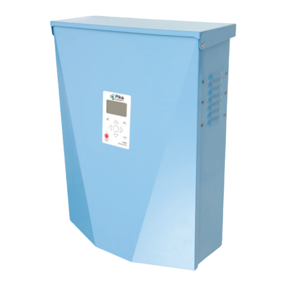
About Pika Islanding Inverters: X7602/X11402 About Pika Islanding Inverters: X7602/X11402 Islanding Inverters connect to the Pika PV Link optimizers to form the Pika Energy Island system for grid-tie solar-plus-storage. Upon the loss of grid power, Islanding Inverters disconnect from the grid and provide AC power to support protected loads. The inverter provides islanding power without an external autotransformer. -
Page 8: Section 2: Safety Specifications
FOR A LIST OF AUTHORIZED INSTALLERS IN YOUR REGION. SHOCK RISK: HIGH VOLTAGE ELECTRICITY WARNING: Before installing the Pika Energy Island, read all instructions and caution markings in this guide and installation manual. Consult installation documentation for all other REbus devices on the system. -
Page 9: Safety Shutdown
The Pika Energy Island system can signal to connected devices on REbus to shut down and limit output voltage to a safe level. The red Safety Shutdown button on the front of the Pika Islanding Inverter activates a Safety Shutdown. An external shutdown button may also be installed, given appropriate labeling. -
Page 10: Section 3: Mounting The Inverter
With an assistant, lift the inverter, center it over the bracket, and lower gently. Align the tabs on the wall bracket with the slots on the back of X7602/X11402. Secure the inverter to the wall with two fasteners through the back wall of the wiring compartment. - Page 11 8.5” 8” Wall 24.5” 28.5” 8” 36” 28” Floor Fig 5. X7602/X11402 Mounting Clearances Bracket Screws x 2 Wall Screws x 2 1. Install Bracket 2. Hang Inverter on Bracket 3. Install Internal Mounting Screws Fig 7. X7602/X11402 Hanging Bracket...
-
Page 12: Section 4: Electrical Connections
Protected Loads Panel FOR REFERENCE ONLY: System must be designed and installed by a licensed contractor or engineer in accordance with NEC and local building codes. Refer to Pika String Sizing Guide for solar module configurations with PV Link. WARNING... -
Page 13: Wiring Guidelines
Wiring Guidelines Wiring Guidelines X7602/X11402 includes an integrated AC and DC wiring compartment. As such, proper installation techniques should be employed to restrain service loops and to separate AC, DC and isolated circuits. All installed conductors must be rated for at least 420 V. -
Page 14: Knockout Dimensions And Locations
(DC) side of the wiring compartment. Use reducing washers to accommodate smaller conduit sizes. To maintain the integrity of X7602/X11402’s NEMA 3R enclosure, use raintight or wet locations hubs in compliance with UL514B, the standard for conduit, tubing, and cable fittings. - Page 15 Knockout Dimensions and Locations Fig 10. X7602/X11402 knockout configuration Islanding Inverter Installation Manual M00008-24...
-
Page 16: Grounding
8 conductors. Connect the equipment gounding conductors for all REbus devices to the ground bar. Ensure a good connection for proper REbus communication. Input and output circuits from X7602/X11402 are isolated from the enclosure. The neutral line is not bonded to ground within the enclosure. When required, system grounding is the responsibility of the installer. -
Page 17: Dc Wiring
PV must be connected via PV Link. WARNING: Do not connect raw, unregulated battery output to the inverter. Connect only REbus-compatible smart batteries. Contact Pika Energy for a list of compatible smart batteries. Connect all REbus devices to the DC wiring terminals inside the Islanding Inverter, including REbus-compatible batteries and PV Links. -
Page 18: Ac Wiring
It is the responsibility of the installer to provide sufficient overcurrent protection for the AC grid wiring terminals. Breaker size is not to exceed ampacity of installed conductors. Refer to all applicable codes and regulations when connecting the AC output of X7602/X11402 to AC distribution equipment. -
Page 19: Protected Loads
Protected Loads. This transition takes place in a fraction of a second. Note: The Islanding Inverter cannot provide full three-phase power at the Protected Loads terminals. Contact Pika Energy for design assistance when using the X11400-series to provide backup power. Islanding Inverter PV Array... - Page 20 Protected Loads terminals. An integrated 50A breaker is incorporated into X7602/X11402 to support the Protected loads panel. If you wish to back up an entire main service panel, you must use an external transfer switch. See “Section 5: External Transfer Switches”...
-
Page 21: Connecting Ethernet
Beacon and connecting to the internet. Connect the inverter to the internet to enable online system monitoring. An internet connection also allows Pika Energy to perform remote service, troubleshooting, and software updates. No data is logged onboard Islanding Inverters when internet connectivity is unavailable. -
Page 22: Connecting Current Transformers (Cts)
Zero Export capability. They also allow the inverter to provide information on utility consumption through the front panel LCD screen. CTs are optional for Grid Tie, Clean Backup, and Priority Backup modes. However, Pika recommends including CTs at all installations. -
Page 23: Connecting Cts To The Inverter
Fan out the wires from the Cat 5 cable and connect the CT leads to the appropriate colored wires. Use a RJ-45 breakout adapter (included with the Pika CT Kit), or use wire nuts or crimped splices to make the connections. Use the following pinout table. -
Page 24: Ct Calibration
LCD screen to turn off, then power on the inverter. Approved CTs Contact your distributor for information on purchasing the Pika CT Kit. Most current transformers with a 1:3000 turns ratio will work, but accuracy may vary. -
Page 25: Section 5: External Transfer Switches
During a grid outage, the system enters Islanding Mode and signals the transfer switch to change state. The Protected Loads output on the X7602/X11402 will supply power to the main panel. When grid service returns, the inverter will toggle the transfer switch and resume grid-tied operation. -
Page 26: Controlling An Automatic Transfer Switch (Ats)
Fig 55. Main panel backup configuration using external transfer switch Controlling an Automatic Transfer Switch (ATS) To control an automatic transfer switch (ATS), use the Pika ATS Control Adapter. The ATS Control Adapter is sold separately as part of the ATS Control Adapter Kit. - Page 27 Controlling an Automatic Transfer Switch (ATS) To use the ATS Control Adapter, connect the transfer switch control lines and grid sense lines as shown. Then use a Category 5 (Cat 5) ethernet cable to connect the “ATS” port on the ATS Control Adapter to the “TRANS”...
-
Page 28: Ats Behavior And Setpoints
Section 5: External Transfer Switches ATS Behavior and Setpoints In the event of a grid outage, the Islanding Inverter will immediately toggle the transfer switch to provide power to the main panel from the Protected Loads output. The switchover time is typically less than one second. -
Page 29: Section 6: Other Accessories
For instructions on installing and using the Beacon, refer to the Beacon documentation. Tech. Service Connection The Tech. Service RJ-11 jack is for use by Pika Energy service personnel only. Do not attempt to connect any device to this jack without direct instructions from Pika Energy Technical Service. -
Page 30: Section 7: Compliance
Green or bare wire Safety Shutdown X7602/X11402 is equipped with a Safety Shutdown function to help installers comply with the Rapid Shutdown requirements given in Article 690.12 of the National Electrical Code. See “Safety Shutdown” on page 9 for more information on Safety Shutdown functionality, including how to intitiate and exit a shutdown. -
Page 31: Voltage Trip Thresholds
Voltage and Frequency Trip Thresholds Voltage Trip Thresholds The following is a table of the default “As Shipped” fixed voltage trip setpoints. All over voltage and under voltage trip conditions result in a 300-second restart delay time after the trip threshold has been exceeded for the listed number of cycles. -
Page 32: Section 8: System Configurations
Section 8: System Configurations Section 8: System Configurations The Pika Energy Island is a flexible, highly customizable system which may be configured in a number of ways to meet your needs. Correct system configuration requires selecting the right equipment and also selecting the correct Operational Mode for the system. Refer to the Islanding Inverter Operation Manual for information on Operational Modes and other user- configurable settings. -
Page 33: Section 9: Commissioning And Setup
Commissioning the System Section 9: Commissioning and Setup After successful installation and wiring of X7602/X11402 and other REbus devices, the Pika Energy Island system is ready to be commissioned. All REbus devices are configured and controlled through the X7602/X11402. Connected devices will appear on the LCD display. -
Page 34: Step 2: Select An Operational Mode
Arrow right and press the center button to select “Confirm.” The X7602/X11402 will now be in the new operational mode. Confirm that the mode listed at the top of the ICM screen is the desired mode. -
Page 35: Step 4: Enable Devices
WARNING: Once the inverter is enabled, it will create high voltage at the DC terminals. All Pika Energy Island devices are enabled and configured individually through the inverter control panel. First, enable the inverter. Then follow the same steps to enable your other REbus devices, such as PV Links and smart batteries. -
Page 36: Step 5: Enable Ethernet
Refer to “Enabling Islanding” on page 32 for more information. Step 5: Enable Ethernet Press the left arrow button on X7602/X11402 until the Ethernet Status page appears appears. The MAC address is listed at the top of the screen. If the screen reads “Ethernet Disabled”, follow steps 2 through 4 to Enable ethernet capability. -
Page 37: Registering Your System On Review
All Pika Energy products use REview, a performance monitoring program developed by Pika Energy and embedded in all REbus nanogrid systems. Each Pika Energy Island has its own REview dashboard that collects and reports system performance data at 20-second intervals. -
Page 38: Rebus Cross Talk Between Multiple Inverters
Section 9: Commissioning and Setup REbus Cross Talk Between Multiple Inverters When more than one Energy Island system is installed in the same building, the systems must be configured to prevent cross talk. Cross talk is a phenomenon where separate REbus systems pick up and recieve REbus data from each other without being physically connected. - Page 39 REbus Cross Talk Between Multiple Inverters Use the left and right arrow buttons to navigate to the correct device screen and press the center button to bring up the menu. Highlight ‘Mod. Settings’ and press the center button to select. iii.
-
Page 40: Section 10: Service And Maintenance
The main fuses in the Islanding Inverter are field replacable by a qualified technican. Additionally, the Power Core may be removed and replaced. No other parts of X7602/X11402 are intended for technician replacement. Contact Pika Energy for instructions on replacing the Power Core. -
Page 41: Removing The Wiring Compartment Cover
Two main fuses are installed between the Power Core and the DC breakers. The fuses can be accessed behind the wiring compartment cover. If a main fuse has blown, contact Pika Technical Support to determine the root cause of the issue before replacing a fuse. - Page 42 DO NOT SCALE DRAWING CAUTION: Never replace the fuse with a different size or style. Failure to follow these instructions could void X7602/X11402’s warranty. See either the table on “Replacing Fuses” on page 41 or the fuse label on your inverter’s Power Core cover for required fuse specifications...
-
Page 43: Common Issues
Recovery From an Error State Error events will force X7602/X11402 into a error state where no DC power is exported, though voltage may still be present on REbus from connected devices. To recover a device from an error state, use the front control panel to Disable and then Enable the device. - Page 44 Section 10: Service and Maintenance Islanding Inverter Installation Manual M00008-24...
-
Page 45: Section 11: Technical Reference
Terminal Torques Section 11: Technical Reference Terminal Torques Torque specifications are derived from manufacturer recommendations. Wiring Terminal Torque AC Terminals 1.5 to 1.8 Nm (13.3 to 15.9 lb-in) DC Terminals 1.35 Nm (12 lb-In) Ground Bar 4 to 6 AWG: 5 Nm (45 lb-in) 8 AWG: 4.5 Nm (40 lb-in) 10 to 14 AWG: 4 Nm (35 lb-in) STOP Terminals... -
Page 46: Section 12: Specifications
Section 12: Specifications Section 12: Specifications Quick Reference Specification X7600 Series X11400 Series Units Max. cont. AC power @ 50ºC 11.4 Grid voltage 240 (1-ph) 120/208 (3-ph) Max cont. REbus current (peak) Max cont. grid output current AC terminals wire size 14 to 6 DC terminals wire size 18 to 6... -
Page 47: Detailed Ratings
Detailed Ratings Detailed Ratings Rating Type Alt Rating Name Nominal Units Maximum Input Voltage Maximum nanogrid voltage Range of Input Operating Voltage Nanogrid operating voltage range Maximum input current Maximum nanogrid input current Maximum input short circuit current Maximum nanogrid short circuit current Maximum input source backfeed current to Maximum nanogrid... -
Page 48: Notes
Notes Notes Use the following pages to record notes about your system or to document phone calls with our service department, available M-F 9AM-5PM ET at 207-808-0362. Islanding Inverter Installation Manual M00008-24... - Page 49 Quick Reference Islanding Inverter Installation Manual M00008-24...
- Page 50 Notes Islanding Inverter Installation Manual M00008-24...
- Page 52 35 Bradley Drive #1 Westbrook Maine 04092...
Need help?
Do you have a question about the X7602 and is the answer not in the manual?
Questions and answers