Advertisement
Ultra Tonic™ Pickup Version 3
Installation Instructions for Steel String Guitars
James May Engineering
December 3, 2019
Version 1.0 ©James May Engineering
Scope
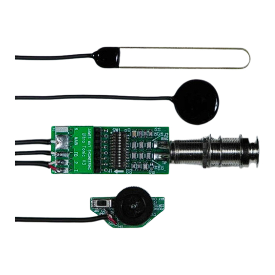
These instructions apply to Version 3 of the Ultra Tonic Pickup, shown here. This version has two sensors
and volume control wired to a disconnecting header so that they can be easily removed from the endpin
circuit board for installation convenience.
The main sensor is a 10mm x 72mm custom piezo bar. The feedback suppression sensor is a 21mm
custom piezo disc that has opposite polarity to the main sensor. They are passively mixed together in
the endpin circuit board by adjusting the 12-position switch for optimum sound quality. The exact switch
position used will vary from guitar to guitar, even of the same model. Instructions for this procedure are
given in sections 4 and 5.
Version 3 of the Ultra Tonic comes standard with a sound-hole mounted volume control. If not required,
it can be removed. See instructions for removing it is section 3.
1
Advertisement
Table of Contents

Related Manuals for James May Engineering Ultra Tonic

Summary of Contents for James May Engineering Ultra Tonic
- Page 1 Version 1.0 ©James May Engineering Scope These instructions apply to Version 3 of the Ultra Tonic Pickup, shown here. This version has two sensors and volume control wired to a disconnecting header so that they can be easily removed from the endpin circuit board for installation convenience.
- Page 2 1. Install the main bar sensor The 10mm x 72mm bar sensor has its crystal sensing area slightly offset to the treble side. This serves to strengthen the high E which would otherwise be weak. There are three important steps for correct positioning: The center line of the sensor should be aligned with the center line of the saddle.
- Page 4 It is highly recommended to use gel superglue or StewMac 30 thick superglue, generously applied so that the whole surface is covered. Press firmly and hold or clamp until the glue sets up which will typically be in about 1 minute. A little squeeze-out is normal and indicates that enough glue was used. Leave undisturbed for 15 minutes.
- Page 5 3. Install the Volume Control Peel off the protective tape and firmly press the volume control board to the underside of the top so that the thumbwheel is accessible through the sound hole. Position it as high up on the sound hole as the bracing pattern will allow.
- Page 6 4. Set the Switch Use some artist tape to protect the top of the guitar. Plug the circuit board onto the pickup connector and let it hang out of the sound hole. If the guitar is unstrung, restring it and bring it up to pitch. Plug it into a PA or full range instrument amplifier so you can judge the sound accurately.
- Page 7 Play the guitar and make a mental note of the bass response, tap the top to get an idea of the tap sensitivity. Crank it up to see where it starts to feedback. Then in turn, one at a time, set the current switch back to the inactive UP position, and activate the next switch to the DOWN position.
- Page 8 (marked R above) and the ground plane on the back. Note: Active (battery powered) secondary pickups are not supported by the Ultra Tonic, since they almost always require a connection to RING to complete the battery connection for power on. You would need to mount a second dedicated end-pin jack to accommodate this.
Need help?
Do you have a question about the Ultra Tonic and is the answer not in the manual?
Questions and answers