
Related Manuals for Powrmatic HEM-NVx Series

Summary of Contents for Powrmatic HEM-NVx Series
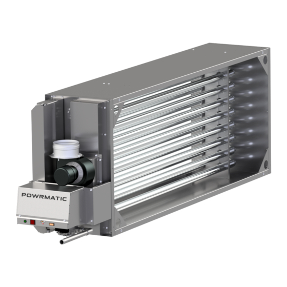
- Page 1 Doc Ref: M103 Issue 3.6 Mar 2020 ® (NVx & SL) User, Installation & Servicing Manual Issue 3.6 Mar 2020 ErP COMPLIANT S E P T E M B E R 2 0 1 8 w w w . p o w r m a t i c . c o . u k...
- Page 2 1. The appliance type and serial number. 2. The original commissioning documentation. As much detail as possible on the fault. 3. Your supplier, or installer, will then contact Powrmatic to make a guarantee claim on your behalf. Conditions of Guarantee 1.
- Page 3 Contents Users, Installation and Servicing Instructions CONTENTS Title Section Contents Page User Instructions Pre Installation Introduction Duties Dimensions Technical data General Requirements Installation Fitting the unit General Identification of Items Electrical Cable Installation Wiring Terminal Connections Wiring Diagrams Commissioning and Testing Servicing Additional Documents Fault Finding Flow Chart...
- Page 4 User Instructions D) Description of Operation If the heater has not been left operational proceed as follows. Important: The heater must NOT be controlled by switching ON and OFF the A) Checks before operating the Air main electrical supply to it. Heater 1) Standard Units The ignition sequence commences each time the...
- Page 5 * Gas Safe Registered Engineer All Powrmatic heaters use gas and electricity to power them, they may also contain moving parts such as pulleys and belts. It would be hazardous to tamper with or attempt to service unless you are a competent person in the field of Gas and Electrical work.
- Page 6 Duties & Dimensions HEM-NVx Model HEM-NVx 10-3 15-4 18-5 25-5 30-6 40-8 50-6 60-7 75-9 100-12 110-13 125-15 150-18 175-21 14.5 17.7 23.6 27.4 36.0 44.8 54.2 67.6 91.9 98.0 112.0 134.9 154.4 Output Min. 11.9 15.7 18.2 23.2 29.0 36.4 49.6 62.5...
- Page 7 Duties & Dimensions HEM-SL Model - HEM-SL 30-6 45-9 50-6 60-12 75-9 75-15 90-18 100-12 125-15 150-18 175-21 200-24 27.0 40.5 45.0 54.2 68.5 67.5 80.4 88.7 116.7 135.7 160.8 178.3 Output 15.0 23.5 23.9 36.4 44.6 41.5 41.6 62.4 70.5 79.9 82.6...
- Page 8 Pressure Drop Graph HEM-NVx Airflow m³/h page no. 8 of 44 HEMNVx & HEMSL Range Users, Installation & Servicing Instructions Doc Ref M103 issue 3.6 Mar 2020.
- Page 9 Pressure Drop Graph HEM-SL 2160 3600 5040 6480 7920 9360 10800 10800 12240 13680 15120 16560 18000 19440 20880 20880 22320 23760 25200 26640 28080 Airflow m³/h 29520 30960 30960 32400 33840 35280 36720 38160 39600 41040 41040 42480 43920 45360 46800 48240...
- Page 10 1.2 Technical Data Injector Sizes & Burner Pressures - Natural Gas - Group H - G20 Net CV (Hi = 34.02MJ/m³) Minimum Inlet Pressure = 20mbar (Max) (Min) HEM-NVx Injectors Burner Gas Rate Burner Gas Rate Pressure (nominal) Pressure (nominal) MODEL Size mm Marked...
- Page 11 1.2 Technical Data Heater Specifications cont - Natural Gas High Fire Low Fire Weights HEM-NVx Min Air Flow Input Input Module Output Output Packaging (Nett) (Nett) only MODEL m³/s m³/h HEMNVx 10-3 10.3 0.34 1220 HEMNVx 15-4 16.3 14.5 11.0 1600 HEMNVx 18-5 19.8...
- Page 12 1.3 General Requirements 1.3.1. Related Documents 1.3.3.2 Meters All HEM heaters comply with the following European An existing meter should be checked, preferably by the Directives: gas undertaking, to ensure that the meter is adequate to deal with the total rate of gas supply required by all Energy Related Product Directive: 2009/125/EC* connected equipment.
- Page 13 1.3 General Requirements 1.3.4.1 Type B flued installations. 1.3.5 Burner/Controls Enclosure. Where AHU's are installed in a plant room (ie not Where the flue system is a Type C12 or C32 the burner and controls enclosure, whether it is part of the unit the within the heated space) having combustion air drawn module is fitted in or an enclosure in its own right, must...
- Page 14 1.3 General Requirements 1.3.6. Ventilation Requirements Type C12 or C32 Installation (these refer to section 2.2 of Type B22 Installation (these refer to section these instructions) 2.2 of these instructions) Air vents shall be permanently open. Air vents shall be permanently open. Figures are for heaters in plant rooms or enclosures ONLY In all cases figures are per heater installed.
- Page 15 Flue terminals may be extended by section. the use of a Powrmatic approved flue piece with sealing Modules may be orientated so that the burner manifold(s) ring or cut down to suit the particular application ensuring is vertical or horizontal.
- Page 16 2.1 Fitting the Unit For horizontal type B flued installations a Combustion of 45° bends should be used being equivalent to 0.5m of flue Air Inlet and Flue Termination piece is supplied for each length. 90° bends may be used but each set will be equivalent module (two Combustion Air Inlets are supplied with to 1.0m of flue length.
- Page 17 2.1 Fitting the Unit 2.1.4.2 Type C Flued Installations The silicone seals supplied are not water tight and should not be used in external vertical applications. A suitable water tight seal or sealant must be used in these instances IMPORTANT: Not applicable for models 150, 175 &...
- Page 18 2.1.6 Electrical Connections 2.1.8 Flue System Only a suitably qualified operative can complete the Only flue systems supplied through Powrmatic Ltd may be electrical installation and must observe the rules in force. used with HEM modules. The flue outlet socket must be connected via the provided flue system to outside air.
- Page 19 2.2 General Identification of Items Upper Burner Set Exhaust Fan Exhaust Burner Set Probe Header Box (behind Heat Shield) Exhaust Header Box Exhaust Fan Flow Sensing Point Exhaust Fan Upper Spark Ignition Probe Gas Valves Gas Inlet Lower Burner Set Controls Panel Spark Ignition...
- Page 20 2.3 Electrical Connections The method of connection to the main electricity supply Warning: THIS APPLIANCE MUST BE must:- EARTHED. - facilitate the complete electrical isolation of the heater(s) via a suitable fused isolator that will prevent remote activation of the heater during servicing (see Warning: Lockout reset is by a switched section 1.2 for ratings).
- Page 21 2.4 Electrical Cable Installation 2.4.2 Single and Dual Modulating Burners * where used t6 t7 2.4.3 Proving Switch Enable Circuit Main fan Proving Switch (suppled by others) page no. 21 of 44 HEMNVx & HEMSL Range Users, Installation & Servicing Instructions Doc Ref M103 issue 3.6 Mar 2020.
- Page 22 2.5 Wiring Diagrams 2.5.3 HEM Single Burner Unit (with HIGH/LOW Burner) page no. 22 of 44 HEMNVx & HEMSL Range Users, Installation & Servicing Instructions Doc Ref M103 issue 3.6 Mar 2020.
- Page 23 2.5 Wiring Diagrams 2.5.4 HEM Dual Burner Unit (with HIGH/LOW Burner) page no. 23 of 44 HEMNVx & HEMSL Range Users, Installation & Servicing Instructions Doc Ref M103 issue 3.6 Mar 2020.
- Page 24 2.5 Wiring Diagrams 2.5.5 HEM Single Burner Unit (with MODULATION Burner) page no. 24 of 44 HEMNVx & HEMSL Range Users, Installation & Servicing Instructions Doc Ref M103 issue 3.6 Mar 2020.
- Page 25 2.5 Wiring Diagrams 2.5.6 HEM Dual Burner Unit (with MODULATION Burner) page no. 25 of 44 HEMNVx & HEMSL Range Users, Installation & Servicing Instructions Doc Ref M103 issue 3.6 Mar 2020.
- Page 26 2.6 Commissioning and Testing Gas Safety (Installation & Use) (Amendment) 2. Switch on the electrical supply at the isolator and Regulations the ignition sequence will commence. After a delay of approximately 45 seconds the ignition spark will be It is law that all gas appliances are installed, generated and the main gas valve(s) energised.
- Page 27 2.6 Commissioning and Testing 2.6.6 Adjustments Maximum Setting. With the controls set to high fire, use an adjustable or 10mm spanner to screw the adjustment nut in to 2.6.6.1. Burner Gas Pressures increase and out to decrease, until the required pressure is obtained.
- Page 28 2.6 Commissioning and Testing Minimum Setting 4. If it is necessary to adjust either the high fire or low fire pressures proceed as follows after removing the plastic Disconnect electrical connection to the regulator and turn cover from the Modulating regulator. the burner back on and wait until the burner pressure has stabilised.
- Page 29 2.6 Commissioning and Testing 3. After the preset 2 minutes of maximum output, the 0 to 10V input signal will take control of the gas valve drive. 4. When the 0 to 10V signal drops below 1V the signal will drop to zero and the gas valve drive signal will be de- energised.
- Page 30 2.6 Commissioning and Testing should be 1.5µA or higher. 2.6.6.2. Final Adjustments 1. In addition it is advisable to check the gas rate using the gas meter dial pointer. Ensure that no other appliances supplied through the meter are in operation. 2.
- Page 31 2.7 Servicing To commence servicing, firstly open the air handler compartment door. 2.5mm Ignition Electrode Spark 2.7.2. Main Burner Assembly Removal 1. Ensure that the gas service valve is turned OFF 2.7.4. Heat Exchanger and then unscrew the union nut situated immediately downstream of it.
- Page 32 10 - 12mm forward of the burner. Components Only parts supplied via or authorised by Powrmatic 2.7.6.4. Limit Thermostat should be used. A short list of parts and part numbers are detailed in section 3.2 of this manual. If in doubt, please contact Powrmatic.
- Page 33 2.7 Servicing 2.7.6.7. Control Box 3. Whilst supporting the fan motor remove the three screws securing the fan motor mounting plate to the fan casing and carefully withdraw the motor, mounting plate 1. Unplug all the electrical connections. and impeller. 2.
- Page 34 3.2 List of Parts Item Description Usage Part No. Gas Valve SIGMA 843 145035208HL-SIT/KIT VR4605AB 145035204HL/KIT Gas Valve Ignition Electrode 142423002 Rectification (Flame Sensor) Probe 142423003 Burner 142400240 Limit Thermostat 142403611 All High/Low 145030846 Control Box (Sequence Controller) All Modulation 145030847 High/Low Governor Head All -/HL...
- Page 35 3.2 List of Parts Item Description Usage Part No. Lockout Reset Switch 143070276 Dungs LGW Pressure Switch 142522174 Pressure Switch HUBA 604 142522177 Exhaust Fan 10-50 140210496 Exhaust Fan 60 & 75 140201505 Exhaust Fan 140210499 Exhaust Fan 110-150 140201503 Exhaust Fan 140201502 Exhaust Fan...
- Page 36 Appendices Appendix 1: HEM-NVx Information required for ecodesign (ErP) Directive 2009/125 Model 10-3 15-4 18-5 25-5 30-6 Rated Heat Capacity 14.5 17.7 23.6 27.4 Minimum Heat Capacity 11.9 15.7 18.2 High Fire 80.0 81.0 81.0 81.0 81.0 Gross Efficiency Low Fire 81.0 81.0 80.0...
- Page 37 Appendices Appendix 2: HEM-SL Information required for ecodesign (ErP) Directive 2009/125 Model 30-6 45-9 50-6 60-12 Rated Heat Capacity 27.0 40.5 45.0 54.2 Minimum Heat Capacity 15.0 23.5 23.9 36.4 High Fire 79.0 79.0 79.0 79.0 Gross Efficiency Low Fire 82.0 81.0 81.0...
- Page 38 - external location. No specific combustion air requirements - external location. Flue can be front or top. Module supplied with Powrmatic flue terminal and flashing Care must be taken to ensure that flue exit point is not in proximity of windows/doors If necessary flue to be extended to a point where it has clearance from windows/doors.
- Page 39 Stand alone application (ie HEM not within a secondary housing/ahu etc) Internal location HEM-SL & HEM-NVx - within open space (ie not plant room) Single module c/w Powrmatic burner enclosure. Combustion air to Powrmatic burner enclosure via Powrmatic combustion air intake grille. Combustion air to space where module is located in accordance with BS6230. Flue can be front or top.
- Page 40 BS6230 Single module c/w Powrmatic burner enclosure. Combustion air ventilation requirements in accordance with BS6230 Plant room ventilation in accordance with BS6230. Flue can be front or top. Powrmatic approved flue to be used. Flue only units - Combustion air to Powrmatic burner enclosure via Powrmatic combustion air intake grille.
- Page 41 Notes: page no. 41 of 44 HEMNVx & HEMSL Range Users, Installation & Servicing Instructions Doc Ref M103 issue 3.6 Mar 2020.
- Page 42 Notes: page no. 42 of 44 HEMNVx & HEMSL Range Users, Installation & Servicing Instructions Doc Ref M103 issue 3.6 Mar 2020.
- Page 43 Notes: page no. 43 of 44 HEMNVx & HEMSL Range Users, Installation & Servicing Instructions Doc Ref M103 issue 3.6 Mar 2020.
- Page 44 Energy Association Powrmatic pursues a policy of continues improvement in both design and performance of its products and therefore reserves the right to change, amend or vary specifications without notice. Whilst the details contained herein are believed to be correct they do not form the basis of any contract and interested parties should contact the Company to confirm whether any material alterations have been made since publication of this brochure.
Need help?
Do you have a question about the HEM-NVx Series and is the answer not in the manual?
Questions and answers