Table of Contents
Advertisement
M74006A.3
Instructions for Installation/Set-up, Operation, Servicing, & Storage
Portable, Outdoor Use-Only, Gasoline Generator
Can be used to power individual appliances plugged directly into the generator's outlets, or as a back-up connection to
a building's power supply (via a professionally installed UL-listed transfer switch).
READ and UNDERSTAND this manual completely before using the generator! Failure to properly set up, operate, and
maintain this generator could result in serious injury or death from carbon monoxide poisoning, electric shock,
fire/explosion, or burns. Generator has been shipped WITHOUT engine oil, Check the oil level using the dipstick and add
oil as needed. In particular, be aware of the following hazards:
Generators give off carbon monoxide, a poisonous gas that can kill you. You CANNOT smell it, see it, or taste it.
• ONLY run generator OUTDOORS and AWAY from building air intakes. NEVER run generator inside any enclosed or semi-enclosed
spaces, including homes, basements, garages, sheds, boxes, RVs, boats or pick-up truck beds. These spaces can trap poisonous
gases, EVEN if you run a fan or open windows.
• Install carbon monoxide alarms inside nearby structures/buildings (battery-operated, or plug-in with battery backup).
• High voltage electricity from generator can kill. DO NOT operate in wet locations. Be sure generator is properly grounded. Use only
UL-listed, outdoor-rated grounded extension cords of proper size.
• NEVER plug the generator directly into a wall outlet. ANY connection to a building's electrical system MUST ISOLATE THE
GENERATOR FROM UTILITY POWER via a UL-listed transfer switch installed by a licensed electrician. Otherwise, back feed from
the generator into the power grid could kill utility workers.
• DO NOT overload generator (per rated capacity), and OPERATE ONLY in an area with adequate cooling ventilation so engine does
not overheat. Exhaust can be extremely hot. Keep muffler at least 7 feet from all combustible objects.
• All fuels are flammable. Never fuel a running or hot engine. Never pump fuel directly into generator at gas station – use approved
container to transfer fuel. Ensure there are no fuel leaks, and keep sources of sparks and flames away.
•
ALWAYS keep a fire extinguisher rated "ABC" nearby.
CHOOSE THE RIGHT GENERATOR FOR YOUR NEEDS. See the "Power Load Planning & Management" section of this manual to
determine your power load requirements and then compare to the generator's rated capacity.
INSPECT COMPONENTS: Closely inspect to make sure no components are missing or damaged. See the "Unpacking & Delivery
Inspection" section for instructions on whom to contact to report missing or damaged parts.
ARRANGE FOR PROFESSIONAL INSTALLATION of a transfer switch if you will be connecting the generator to your building's
electrical system. See the "Installation/Initial Set-Up" section for more information about this requirement.
Owner's Manual
WARNING – READ THIS MANUAL
Electric shock / Electrocution
Any Questions, Comments, Problems, or Parts Orders
Call Powerhorse Product Support 1-866-443-2576
Item Number: 74006
Serial Number: _____________
CO Poisoning
Fire / Explosion
STOP!
1
Advertisement
Table of Contents

Related Manuals for Powerhorse 74006


Summary of Contents for Powerhorse 74006
- Page 1 ARRANGE FOR PROFESSIONAL INSTALLATION of a transfer switch if you will be connecting the generator to your building’s electrical system. See the “Installation/Initial Set-Up” section for more information about this requirement. Any Questions, Comments, Problems, or Parts Orders Call Powerhorse Product Support 1-866-443-2576...
-
Page 2: Hazard Signal Word Definitions
Hazard Signal Word Definitions This is the safety alert symbol. It is used to alert you to potential personal injury hazards. Obey all safety messages that follow this symbol to avoid possible injury or death. DANGER indicates a hazardous situation, which if not avoided, will result in death or DANGER serious injury. -
Page 3: Table Of Contents
Table of Contents Hazard Signal Word Definitions ........................2 About Your Generator ..........................4 Specifications ............................... 6 Safety Label Locations ..........................7 Machine Component Identification ......................9 Power Load Planning & Management ...................... 18 Installation / Initial Set-Up: 1. Unpacking & Delivery Inspection ......................21 2. -
Page 4: About Your Generator
“Maintenance & Repair” sections within this generator manual. Powerhorse is constantly improving its products. The specifications outlined herein are subject to change without prior notice or obligation. The purchaser and/or user shall assume liability for any modification and/or alterations of this equipment from original design and manufacture. - Page 5 About Your Generator Warranty Registration Please fill in the warranty registration information in the back of this manual and have it on hand when you call in on a warranty claim or replacement parts. ATTENTION: Rental companies and private owners who loan this equipment to others! All persons to whom you rent/loan this generator must have access to and read this manual.
-
Page 6: Specifications
5A is BK-ATC-5J (Orange) (Automotive Style) 20A is BK-ATC-20J (Yellow) Unit Dimensions Length 37.4" (950 mm) Width 30.1" (765 mm) Height 30.4" (773 mm) Dry Weight 322 lbs. (146 kg) Any Questions, Comments, Problems, or Parts Orders Call Powerhorse Product Support 1-866-443-2576... -
Page 7: Safety Label Locations
Always make sure safety labels are in place and in good condition. If a safety label is missing or not legible, order new labels or unsafe operation could result. To order replacement safety labels, call Powerhorse Product Support at 1-866-443-2576. - Page 8 Safety Label Locations...
-
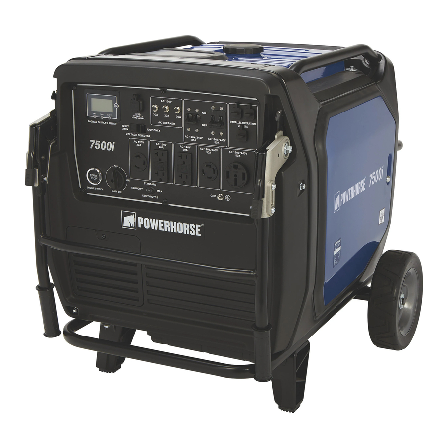
Page 9: Machine Component Identification
Machine Component Identification Ref. Description Ref. Description Fuel Tank Cap Muffler Control Panel Carbon Canister Handles Air Cleaner Battery Location Carburetor Inverter Location Left Side Cover Right Side Cover Spark Plug Rear Handle Spark Plug Cover... - Page 10 Machine Component Identification REFERENCE GUIDE Reference 1 – Fuel Tank Cap The fuel tank cap seals the fuel in the tank. Reference 2 – Control Panel An electrical device that contains receptacles, switches and other electrical devices. Reference 3 – Handles Provides a means for moving the generator.
- Page 11 Machine Component Identification Ref. Description Ref. Description Digital Display Meter Grounding Post Voltage Selector Switch 120V/240V 30 Amp Locking Receptacle (NEMA L14-30R) USB Receptacle (Type A) 120V 20 Amp Duplex Receptacles (NEMA 5-20R) GFCI AC Circuit Breakers ESC Switch (Engine Smart Control) AC 120V/240V 30A Circuit Breaker Main Switch AC 120V/240V 50A Circuit Breaker...
- Page 12 Machine Component Identification ESC Throttle/ Engine A switch used to reduce fuel consumption and noise. Control 1. STANDARD position: When the ESC switch is on STANDARD, the engine runs Switch at the rated (3100 RPM) when the electrical load is less than 4.5kW. 2.
- Page 13 Machine Component Identification Engine Switch Button used to start the generator without pulling on the recoil starter grip. (Electric Start/Stop Press the engine switch to electric start the generator. Button) Make sure the intervals between pressing the switch is longer than 10 CAUTION: seconds.
- Page 14 Machine Component Identification Liquid Crystal The main section of the LCD screen shows the operating status of the generator. Display (LCD) Screen Pushing the operation key will toggle through the status of the generator including: voltage, amperage, power, frequency, rpm, run time, cumulative time, remaining run time, and battery voltage.
- Page 15 Machine Component Identification Liquid Crystal Display (LCD) Screen (21) Battery (Voltage greater than 12V) (25) Battery (More than 8V and less than 12V)
- Page 16 Machine Component Identification Liquid Crystal When the main switch is in the “ON” position, the LCD screen will display Display (LCD) Screen maintenance tips only if the engine is not started or when the engine is running normally. Press the operating key to clear and reset.
- Page 17 Machine Component Identification Low Oil Warning When the oil level falls below the lower level, the oil warning indicator lights up Light and the engine stops automatically. The engine will not start again until oil has been added. Note: If the engine stalls or does not start, turn the engine switch to “ON” and then pull the recoil starter.
-
Page 18: Power Load Planning & Management
Power Load Planning & Management WARNING • NEVER exceed the rated wattage capacity of your generator. • OVERLOADING may cause SERIOUS DAMAGE to the generator and attached electrical devices, and may result in fire. Your generator MUST BE SIZED PROPERLY to provide both the running and starting (surge) wattage of the devices you will be powering. - Page 19 Power Load Planning & Management Running Watts Starting Watts Device (Continuous) (Surge) Clothes Dryer (gas) 1200 Clothes Washer 1150 2300 Coffee Maker 1750 Deep Freezer 1000 Desktop Computer w/ 17" monitor Dishwasher (hot dry) 1500 1500 Drill: 1/2in., 5.4 Amps Drill: 3/8in., 4 Amps DVD/CD Player Electric Fence: 25 Miles...
- Page 20 Power Load Planning & Management To calculate the running and starting wattage requirements for the devices you will be powering, follow these steps: 1. Make a list of all electrical devices you will be powering at the same time with the generator. 2.
-
Page 21: Installation / Initial Set-Up
Installation / Initial Set-Up There are a number of important steps required to set up your generator for initial use. These steps are: Steps for Installation / Initial Set-Up 1. Unpacking & delivery inspection. 2. Assembly. 3. Planning the power load to stay within the generator’s rated capacity. 4. -
Page 22: Assembly
Installation / Initial Set-Up 2. Assembly Installing Leg You must assemble your generator before it can be used. Installation of the front leg and Wheel Kit support kit and wheel kit will provide airflow space between the ground and the inlet of the generator. - Page 23 Installation / Initial Set-Up Battery Your generator is equipped with an electric starter which requires a 12-volt DC battery. The Connection battery is supplied with the generator and will need to be connected upon first use. Follow the instructions detailed below for connecting and disconnecting the battery. Batteries are hazardous because they contain caustic acid, can WARNING: emit explosive gases, and can cause electric shock.
-
Page 24: Planning The Power Load
Installation / Initial Set-Up 3. Planning the Power Load Plan your power load so that you do not exceed the generator’s rated capacity. See the “Power Load Planning & Management” section of this manual to review how to plan and manage power loads for the generator. - Page 25 Installation / Initial Set-Up In addition to isolating your generator from the utility system, the transfer switch connects your generator to a limited set of circuits in your building that have been chosen as critical to operate during a power outage. The generator may not power your entire home -- you must work with the installing electrician to determine which devices/appliances you wish to power during an outage.
- Page 26 Installation / Initial Set-Up 7. All extension and appliance cords must be in good condition and not worn, bare, frayed, or otherwise damaged. Use of damaged electric cords can cause electric shock or fire. WARNING: Note: If an extension cord becomes hot to the touch, it is overloaded or damaged and must be replaced.
-
Page 27: Selecting A Suitable Site
Installation / Initial Set-Up 5. Select a Suitable Site Before using the generator, you must select a suitable OUTDOOR location for installation and operation. This location should meet all the criteria listed below. You must choose a suitable site for operating your generator to avoid equipment WARNING: damage and/or injury and possible death from carbon monoxide poisoning, electric shock, or fire. - Page 28 Installation / Initial Set-Up Adequate Cooling The generator needs adequate, unobstructed flow of air to allow for proper Ventilation cooling of engine and generator head. Heat build-up from inadequate ventilation can result in fire, WARNING: posing a serious risk to nearby persons and structures. •...
-
Page 29: Grounding The Generator
Installation / Initial Set-Up 6. Grounding the Generator Always ensure the generator is properly grounded to prevent electrical shock. You must always ground the generator by the following method when using the generator as a portable electrical source: 1) Drive a 3/4" or 1" copper pipe or rod into the ground close to the generator. The pipe/rod must penetrate moist earth –... -
Page 30: Operation
Operation Once you have set up your generator for use, it is time to start your generator. The following are the procedures necessary for safe, successful operation of your generator. Operation Procedures 1. General Safety Rules for Operation 2. Preparing for Operation 3. - Page 31 Operation • Malfunction during operation. Immediately turn off the generator if any of the following conditions arise during operation: o Excessive change in engine speed, slow or fast o Overheating in load connecting devices o Sparking or arcs from generator o Loss of electrical output o Receptacle damage o Engine misfire...
- Page 32 Operation Static Electricity and Filling the Gasoline Tank Static electricity can initiate from ungrounded gasoline tanks or containers, from flowing gasoline, and from persons carrying a static electric charge. Static electricity can explosively ignite gasoline vapors that are present during the fueling process, resulting in serious burns to nearby persons.
-
Page 33: Preparing For Operation
Operation 2. Preparing for Operation Position generator in accordance with the instructions given in Installation & Initial Position Set-up, Step 5: Select a Suitable Site of this manual. Generator Operate outside only, on dry, level ground with adequate clearance and ventilation. Generators give off carbon monoxide exhaust, a poisonous gas WARNING: that can kill. - Page 34 Operation 4) Fill with the recommended amount and type of engine oil (See Specification section). Check oil level then install and tighten the oil filler cap. Oil Filler Cap 5) Close door and turn screw ¼ turn until secured. Screw (See the specification section for oil type and capacity.) Never open oil port while engine is running.
- Page 35 Operation Use extreme care when handling gasoline. Carefully follow all the instructions in this section to avoid the following conditions which could result in gasoline ignition: • gas vapor collection inside enclosures • static electric sparks • sparks from electric wiring, batteries, or running engines •...
- Page 36 Operation A static electric spark can explosively ignite gasoline vapor, WARNING: resulting in a flash fire that could cause serious injury or death. To avoid static electric sparking while filling the gasoline tank, the following steps must be followed to minimize and safely dissipate static electric charge build- up before and during the fueling process: •...
- Page 37 Operation Personal 1) Hearing can be damaged from prolonged, close-range exposure to the type of noise Protection produced by this generator. The use of ear plugs or other hearing protection device is recommended for persons working within 15-20 feet of the running generator for an extended period of time.
-
Page 38: Starting The Generator
Operation 3. Starting the Generator After you have completed the pre-start checklist procedures, you are ready to start the generator. To start the engine: 1) Turn the ESC throttle switch to “Standard”. 2) Turn the Main Switch to “ON”: Ignition circuit is switched on. Fuel is switched on. -
Page 39: Checking Generator Output
Operation 4) Recoil Start - Pull slowly on the recoil starter until it is engaged, then pull it briskly. Recoil Starter Note: Grasp the generator handle firmly to prevent the generator from falling over when pulling the recoil starter. 5) Under long, continuous-run operating conditions, be prepared to: a. -
Page 40: Connecting Loads
Operation 5. Connecting Loads Be careful when connecting loads so as not to overload the generator, especially if you are powering devices with motors that require a higher starting power load. Instructions are provided below for connecting loads when you are using the generator: o As a portable power source o When connecting to a building as a back-up power source Do not overload generator. -
Page 41: Ac Parallel Operation
Note: Most motorized appliances require more than their electrical rating for start-up. When an electrical motor is started, the overload indicator (red light) may come on. This is normal if the overload indicator (red light) goes off within 4 seconds. If the overload indicator (red light) stays on, contact Powerhorse Product Support at 1-866-443-2576. - Page 42 Operation Connect Parallel 1. Turn off both generators. Cables 2. Connect the parallel operation cable in the correct orientation with the red plug on the left and the black plug on the right to their corresponding parallel operation outlets designated with the red O-ring and the black O-ring on each of the generator control panels.
-
Page 43: Storage & Exercise
Operation Storage & Exercise When you are finished using the generator, you must: o Disconnect all loads. o Allow generator to completely cool down. o Store the generator properly. o Plan on exercising the engine regularly unless the generator is prepared for long-term storage. Detailed instructions are provided below. - Page 44 Operation Prepare Engine for 1 Add fuel stabilizer: to 2 Months Storage 1. Ensure gasoline tank is full. 2. Add fuel stabilizer to fuel tank. 3. Run engine at least 10 minutes after adding stabilizer to allow it to enter the fuel system.
-
Page 45: Maintenance & Repair
• Repair. Major service, including the installation or replacement of parts, should be performed only by a qualified electrical service technician. Obtain factory approved parts from Powerhorse Product Support at 1-866-443-2576. • Replacement parts. If a part needs replacement, only use factory approved repair parts. - Page 46 Maintenance & Repair (continued) d) Remove the oil filler cap Inspect the O-ring e) Place an oil pan under the engine. Remove the oil drain bolt inspect the oil filler cap packing f) Reinstall the oil drain bolt g) Reinstall the rubber plug to bottom of the generator. h) Fill with the recommend amount and type of engine oil, then install and tighten the oil filler cap .(See Specification section for oil type...
- Page 47 Maintenance & Repair (continued) Air Filter Check/Replacement a) Place the generator on a level surface. b) Open left side cover by turning screw ¼ turn. c) Remove the air filter housing cover, paper filter, and foam element. d) Replace paper filter with a new filter. DO NOT clean paper air filter with compressed air.
- Page 48 Maintenance & Repair (continued) e) Wash the foam element in a solution of household detergent and warm water, rinse thoroughly, and let air dry. f) Soak the foam element in oil and squeeze out excess oil. The foam element should be wet but not dripping. DO NOT twist or wring out the foam element when NOTICE: squeezing;...
- Page 49 Maintenance & Repair (continued) Standard Spark Plug: BPR6ES/BP6ES (NGK) F7RTC/F7TC Spark Plug Gap: 0.6-0.8mm (0.024-0.031in) e) Install the spark plug. Torque specification is 14.8 ft. lbs. If a torque wrench is not available, a good estimate of the correct torque is 1/4- 1/2 turn past finger tight.
- Page 50 Maintenance & Repair (continued) Draining the Carburetor a) Open right-side cover by turning screw ¼ turn. b) Loosen the carburetor drain screw with a flat blade screwdriver. c) Drain fuel into suitable container. d) Tighten the carburetor drain screw. e) Close side cover and tighten the screws. Screw Carburetor Drain Screw...
- Page 51 Maintenance & Repair (continued) c) Clean the flame screen and spark arrester. Replace if damaged. When cleaning, use a wire brush lightly to avoid NOTICE: damaging or scratching muffler screen and spark arrester. d) Reinstall the spark arrester, flame screen, and sparker arrester bracket. e) Secure the spark arrester bracket with securing bolts.
- Page 52 A high-altitude kit includes a carburetor jet resized to help correct air / fuel mixture at altitude. To order a high-altitude kit or if you have additional questions, go to www.northerntool.com or contact us at 1-866-443-2576 – Powerhorse. Please note, engines with the high-altitude kit installed operated at lower altitudes could cause severe engine damage and affect emissions compliance.
-
Page 53: Troubleshooting
If a part needs replacement, only use parts that meet the manufacturer’s specifications. Replacement parts that do not meet specifications may result in a safety hazard or poor operation of the generator. Contact Powerhorse Product Support at 1-866-443-2576 for any questions, problems, or parts orders. -
Page 54: Summary Of Important Safety Information For Operation
Summary of Important Safety Information for Operation This section provides a summary of the various safety procedures and measures that have been presented throughout the manual. Keep this summary handy and refer to it to refresh your memory about how to safely use your generator. - Page 55 Summary of Important Safety Information for Operation Installation / Initial Set-up Safety • Dry, level surface. Situate generator on a dry, firm, level surface. Ensure generator sits level and will not slide or shift during operation. Block wheels if applicable. •...
- Page 56 Summary of Important Safety Information for Operation • Fuel outdoors. Fill fuel tank outdoors – never indoors. Gasoline vapors can ignite if they collect inside an enclosure. Explosion can result. • Use approved container. Never pump fuel directly into engine at gas station. Static charge can build and ignite fuel. Use a UL-listed fuel container to transfer gas to the engine.
- Page 57 Summary of Important Safety Information for Operation • Malfunction during operation. Immediately turn off the generator if any of the following conditions arise during operation: Excessive change in engine speed, slow or fast Overheating in load connecting devices Sparking or arcs from generator Loss of electrical output Receptacle damage Engine misfire...
-
Page 58: Generator Exploded View
Generator Exploded View – 74006 Rev A.3... - Page 59 Generator Exploded View – 74006 Rev A.3...
- Page 60 Generator Parts List – 74006 Rev A.3 Part # Description Part # Description Bolt with flange M8x26 Kit # 7 Right leg Kit # 16 Flat washer M12 Kit # 8 Pin clip Washer M12 Kit # 8 Flat washer M18...
- Page 61 Generator Parts List – 74006 Rev A.3 Ref # Part # Description Kit # 17 Tank 800335 Rear muffler shroud Right seal ring Kit # 15 Left seal ring 800336 Rear plastic panel 800337 Bolt with flange M6X35 800338 Rear frame handle...
-
Page 62: Generator Kit Exploded View
Generator Kit Exploded View – 74006 Rev A.3 Kit #3 Kit #1 Kit #2 Kit #4 Kit #5 Kit #7 Kit #6 Kit #9 Kit #8 Kit #10 Kit #11 Kit #12 Kit #13 Kit #14 Kit #15 Kit #18... - Page 63 Generator Kit Parts List – 74006 Rev A.3 Kit Ref Kit Part # Description 800250 Battery cover kit 800251 Fuel knob kit 800252 Control panel kit 800253 Fuel filter kit 800254 Inverter assembly 800255 Battery bracket kit 800256 Front leg support kit...
-
Page 64: Engine Exploded View
Engine Exploded View - 800342... - Page 65 Engine Parts List - 800342 Part # Description Part # Description 800299 800381 Location pin Bolt with flange M6X10 Or Kit # 26 Kit # 29 Cylinder head gasket Kit # 19 Hose clamp 800382 Cylinder head 800383 Stud, Intake 800301 Bolt with flange M6X20 800384...
-
Page 66: Engine Kit Exploded View And Parts List
Engine Kit Exploded View and Parts List - 800342 Kit #19 Kit #21 Kit #22 Kit #20 Kit #23 Kit #24 Kit #25 Kit #26 Kit #27 Kit #29 Kit #28 Kit Ref Kit Part # Description 800266 Fuel pump kit 800267 Recoil starter fan kit 800268... -
Page 67: Limited Warranty
Powerhorse. Powerhorse will not provide for replacement of complete products due to defective parts. Any costs incurred due to replacement or repair of items outside of a Powerhorse approved facility is the responsibility of the buyer and not covered under warranty. -
Page 68: California Proposition 65 Information
WARNING: This product can expose you to chemicals including gasoline engine exhaust, which is known to the State of California to cause cancer, and carbon monoxide, which is known to the State of California to cause birth defects or other reproductive harm. For more information go to www.P65Warnings.ca.gov.
Need help?
Do you have a question about the 74006 and is the answer not in the manual?
Questions and answers