Table of Contents
Advertisement
Quick Links
Advertisement
Table of Contents

Related Manuals for QSI 600 Series

Summary of Contents for QSI 600 Series
- Page 1 600 Series User Guide Revision 4 July 2019 Disclaimer: The specification in this document are subject to change without notice. All trademarks are properties of their respective owners, and are used herein for informational purposes only. Quantum Scientific Imaging Phone +441603 740397...
- Page 2 Table of Contents 1. GETTING STARTED page 4 What’s in the box Get to know your camera Install software and drivers Confirm installation and camera operation A basic guide to getting started with SGP 2. CAMERA FEATURES AND OPERATION page 12 Camera attachment options Attach the camera to the telescope Electrical connections...
- Page 3 Anti-blooming CCD’s Microlenses Single shot colour CCD’s Single versus noise Reducing noise in CCD images Dark frames Flat fields Bias frames Stacking images Colour images 4. ACCESSORIES page 39 T-mount adapter 2” nosepiece 1.25” nosepiece C-mount adapter SLR lens adapter Liquid heat exchanger Recirculating pump Colour filter wheel...
-
Page 4: Getting Started
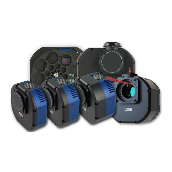
The QSI 600 Series Camera Family Showing Different Body Configurations What’s in the box Your QSI 600 Series camera was shipped in a soft travel case with custom-cut foam to provide protection. Please take a few minutes to examine your camera to make sure that it has arrived in good condition, and that the case contains the items listed below. - Page 5 • Camera body • Nosepiece - 2” or 1 ¼” depending on configuration • Mounting adapter - standard T-mount, or optional mounting adapter • Body cap - matching body cap for mounting adapter • AC Power Adapter - Universal AC power supply (100-240VAC, 50-60Hz) with detachable, region-specific AC power cord •...
- Page 6 5-position internal colour filter wheel. The depth of the Camera Cover on your camera may differ depending on the internal options installed. 8-position CFW models have a larger front cover. See the “QSI 600 Series WSG User Guide Supplement” for additional details on WSG models with Integrated Guider Port.
-
Page 7: Install Software And Drivers
Note: For the most up to date version of the software and guides please go to https://qsimaging.com/drivers-software/ The QSI 600 series cameras include either a CD or a USB flash drive containing the drivers for the cameras plus plug-in’s for Astroart and MaximDL. -
Page 8: Confirm Installation And Camera Operation
Plug in the camera. Please plug in the power supply followed by the USB cable, your computer will now finish the installation and you should see two new devices in windows device manager as shown below. Confirm installation and camera operation After the successful installation of the camera and the associated software is complete, you can quickly test your camera with SGP or the software application of choice. - Page 9 Open SGP and you will be presented with the screen as shown below. Select QSI Camera and QSI Filter Wheel as shown below and power your camera on if it isn’t already on.
- Page 10 Select the settings icon. You will be presented with the screen below. Once the camera has been correctly identified it will be named as the connected camera in the pull-down box. Please select the camera and click on OK.
- Page 11 Once your camera has booted up successfully select “connect” and the camera will connect to the software.After the camera has been set up in ASCOM you will then need to set up the filter wheel. Click on the setting button as above and you will be presented with the screen below once the filter wheel has been located.
-
Page 12: Camera Attachment Options
Attach the camera to your telescope The picture below shows a QSI 500 Series camera with 2" nosepiece being fitted to the 2" focusing tube of a refracting telescope. Always use the largest nosepiece that your telescope... -
Page 13: Electrical Connections
With the correct diameter nosepiece firmly screwed in to the front of the camera, carefully guide the nosepiece into the eyepiece adapter on your telescope. Tighten any retaining screw or screws to ensure the camera is stable and will not slip or move when the orientation of the telescope changes. -
Page 14: Usb Connector
Note: Power up initialisation can take up to 6 seconds. It is not possible to connect to the camera from an image application during this time. Any attempt to do so will cause an error message to be displayed by your imaging application. Note: The camera is designed to operate on stable, regulated 12 V DC power and Consumes less than 2 amps at full power. -
Page 15: Guider Control Port
Powered hubs are not necessary for operation. Guider Control Port All QSI 600 Series cameras have a Guider Control Port that can be used in conjunction with CCD imaging software to guide your telescope mount for long- duration astro-imaging. Ordinarily, the Port is only operational if the camera is being used as the Guider camera, or if you’re using the QSI camera as your main imaging camera and have configured your software... -
Page 16: Cooling The Camera
Peltier Effect to cool the CCD. When power is applied to a TEC, one side of the device gets cold and other side gets hot, essentially pumping heat from the cold side to the hot side. All QSI 600 Series cameras employ a two-stage TEC to increase the differential cooling effect. -
Page 17: Liquid-Assisted Cooling
Good results can be obtained with the CCD cooled to -10ºC when taking modest length exposures. This is easy to achieve with forced air cooling on a QSI 600 Series camera when the ambient air is at 25ºC (77ºF) or lower. For most CCDs used in QSI 600 Series cameras, dark current is reduced by half for every ≈6ºC drop in the temperature of the CCD. -
Page 18: Controlling The Cooler
Note: Refer to the specification sheets at the end of this guide for the exact cooling specification for your particular camera model. Keep in mind that ambient temperature changes, air movements, and even relative humidity can affect the temperature that the camera can reach and maintain. - Page 19 1.25" mounted filters or un-mounted 31mm filters. In the case of the QSI-6162 the filter wheel is designed to hold five or eight 2” mounted filters or 50.8 mm un-mounted filters. The following image shows a 5-position filter wheel with filter positions 1-4 occupied by red, green, blue and luminance filters respectively.
-
Page 20: Advanced Setup Options
SGP profile box. This will bring up the ASCOM QSI setting box. If the Camera Model list box does not indicate your QSI camera please select it from the USB Interface drop-down box. From here you can control things such as the LEDs, Sound on and off, fan mode, gain, Pre-exposure flush, Optimisation, the filter wheel setup and Enabling pixel masking. -
Page 21: Camera Selection
Camera Selection USB Interface Select the specific QSI camera that you wish to control from those listed in the USB Interface list box. Cameras are tracked by their serial number. That is the number located in parenthesis, and will match the number engraved on the camera nameplate / desiccant cover. -
Page 22: Imaging Options
CCD retains less stray charge between exposures. When using full-frame CCDs such as in the QSI 616 and 632, the Flush options correspond to 0, 1, 2, 4, and 8 flush cycles respectively. With interline transfer CCDs a variety of flushing techniques are used by the different Flush options to provide increasingly aggressive flushing of stray charge before beginning an exposure. - Page 23 Gain offers three options 1. High Gain - High Gain is optimized for 1x1 binning. 2. Low Gain - Low Gain is optimized for binning higher than 1x1. 3. Auto - Auto selects “High” gain for images with 1x1 binning and “Low” gain for images with binning higher than 1x1.
- Page 24 Click the OK button to save your changes or the Cancel button to abort them. This will return you to the Setup QSI Universal window. Click OK again and youll be returned to the Setup tab in the Camera Control window.
-
Page 25: Status And Notification
Status and notification QSI 600 Series cameras utilize a variety of methods to inform the operator of the cameras operation, status and other events. A built-in LED Status Indicator and audible Beeper provide notification at the camera. In the event of a serious internal error, the camera will also pass a descriptive error code back to the controlling application which then reports it to the user. - Page 26 Camera soft error state indication Flash Red: 1 Flash Yellow:1 The camera is over-temperature. Camera has exceeded the 40°C maximum recommended operating temperature for the internal electronics and enclosure. This sequence will repeat every four seconds as long as the camera remains “over- temperature”. Flash Red: 1 Flash Yellow: 2 The CCD is under-temperature.
-
Page 27: Audible Beeper
Many of these messages have straightforward text descriptions of the event. Others messages may include only a numeric code. If you get a message indicating an error, record the text message or numeric code in the event that you need to contact QSI Customer Support. - Page 28 A CCD is organized in a two-dimensional array of pixels. The CCDs used in the QSI 600 Series cameras at the time of printing range from roughly 400,000 pixels (768W x 512H) to 16 million pixels (4499 W x 3599 H).
-
Page 29: Anti-Blooming Ccds
a full-frame CCD. Interline transfer CCDs give up some sensitivity because a sizeable portion of the potential light gathering surface of the CCD is occupied by the masked storage columns. The key benefit of interline transfer CCDs is that the shifting of the image into the masked storage column acts like a very precise electronic shutter allowing short, accurate exposures. - Page 30 Adding microlenses to a front-illuminated CCD will raise the quantum efficiency of the CCD. Typical peak QE values for the CCDs used in QSI 600 Series cameras range from 35% to over 80%. Microlens models tend to have the highest QE, while anti- blooming gate models tend to have the lowest QE.
-
Page 31: Signal Versus Noise
Single-shot colour CCDs, like those found in almost all general use digital cameras, are made by placing red, green and blue filters over adjacent pixels in the CCD. The image processing program then has to separate the three different colour images and recombine them into a single colour image. -
Page 32: Reducing Noise In Ccd Images
from dark to light from one corner or side of an image to the other, and especially as low contrast images — the result of a reduced signal to noise ratio. Achieving high dynamic range, low noise images from a cooled CCD camera requires a basic understanding of how CCDs work and the different sources of noise that can reduce the quality of your images. - Page 33 Most pixels on a CCD build up dark current at a constant rate but that rate will vary slightly from pixel to pixel. A subset of the pixels in a CCD will build up dark current at a dramatically different rate from the average.
-
Page 34: Flat Fields
Original image Original image minus dark frame Look at the two images above. The top image is the original image as it came out of the camera. The bottom image has had the average of 5 dark frames subtracted from it. Note that the bright pixels have been virtually eliminated leaving a smooth black sky background. - Page 35 Good flat fields require an exposure time such that the pixel wells are filled to approximately half their full capacity. With a QSI 600 Series camera you should strive to achieve average pixel values between 20,000 and 30,000 out of a total of roughly 65,000. You should experiment with exposure times to yield that result.
- Page 36 dark current. Taking 16 flat fields and 16 flat-darks will yield excellent results. Luckily because flat fields tend to use fairly short exposures, you can often take a full series of flat fields and flat- darks in just a few minutes. The resulting master Flat Field is used to scale the pixel values in the light frame, eliminating the effects of pixel non-uniformity, optical vignetting and dust on the optical surfaces.
- Page 37 frames and flat fields, also take a series of at least 16 bias frames. That completes your full set of calibration frames. Stacking images After calibrating each of your raw images with dark frames, flat fields and bias frames, combining or “stacking” multiple sub-exposures can be used to further reduce the noise in your images.
- Page 38 RGB image on its own. Your processing software can be used with your QSI 600 Series camera to collect and catalogue the various filtered images that you’ll need to create LRGB images. As with any images, you’ll want to collect multiple frames through each filter and then calibrate and combine...
- Page 39 C-mount threads, 1” x 32tpi. There are two different versions of the C-mount adapter plate which provide the correct focal depth for slim and mid-sized QSI 600 Series cameras. You must use the correct version of the C-mount adapter plate for your body style in order to achieve focus at infinity.
- Page 40 The liquid heat exchanger (LHX) provides additional cooling of the CCD beyond what can be achieved using the standard air cooling. The liquid heat exchanger attaches to the back of the QSI 500/600 Series camera (excluding the QSI-6162) using four screws. Refer to the camera specifications to determine the temperature differential that can typically be maintained when using the LHX.
- Page 41 See the Care & Maintenance section below for instructions on removing and installing the colour filter wheel. See the WSG User Guide Supplement for details on accessories specific to WSG models. See the Accessories page on the QSI web site for complete details on available accessories: https://qsimaging.com/products/...
-
Page 42: Care And Maintenance
Care and Maintenance Cleaning the exterior The QSI 600 Series cameras are machined from high quality 6061 aluminium with a very durable anodized finish that resists most scratches and fingerprints. Use a soft cloth to remove dirt or spots from the exterior surface of the camera. - Page 43 Installing or removing 31/50.8mm colour filters Some QSI 600 Series colour filter wheels are configured to hold unmounted 31/50.8 mm filters. Filter wheels capable of holding 31/50.8 mm unmounted filters have a screw hole between each filter position. Note the retaining screws in the image above between each filter position which hold the unmounted filters in place.
- Page 44 The longer screws go through the 8-position CFW Adapter Plate and screw directly into the QSI 600 Series body, shown with blue arrows below. Lift the cover straight up to expose the colour filter wheel.
-
Page 45: Cleaning The Ccd Cover Glass
Cleaning the colour filters As with any precision optical surface, the optical coatings or glass of colour filters can be permanently damaged by improper cleaning procedures. For best results follow the cleaning instructions that came with your filters. It is best to clean the filters infrequently and use the least intrusive of the methods below to remove any dust or fingerprints. - Page 46 For the QSI-6162 camera please contact QSI support for the environmental chamber maintenance instructions...
-
Page 47: Technical Support
If you can’t find the answer to your question on our web site please contact QSI technical support at shown below. Email is preferred. Internet: https://qsimaging.com/support/technical-support/#... - Page 48 Appendix A 600 Series Specifications General camera specifications (I, s, ws models) Feature QSI 600i QSI 600s QSI 600 ws Electronic Shutter 100µsec to 240 minutes 100µsec to 240 100µsec to 240 minutes (Interline transfer minutes CCDs only) Mechanical Shutter 0.03 seconds to 240...
- Page 49 Temperature: 20 degC to 30 degC, Humidity: 10% to 90% non-condensing Computer Connectivity 600 series – USB 2.0 High Speed (USB1.1 compatible) Other ports Optically isolated 4 channel control port for telescope guiding (or other application specific control in some...
- Page 50 General camera specifications (wsg, ws-8, wsg-8 models) Feature QSI 600 WSG QSI 600 ws-8 QSI 600 wsg-8 Electronic Shutter 100µsec to 240 minutes 100µsec to 240 minutes 100µsec to 240 minutes (Interline transfer CCDs only) Mechanical Shutter 0.03 seconds to 240 0.03 seconds to 240...
- Page 51 Temperature: 20 degC to 30 degC, Humidity: 10% to 90% non-condensing Computer Connectivity 600 series – USB 2.0 High Speed (USB1.1 compatible) Other ports Optically isolated 4 channel control port for telescope guiding (or other application specific control in some...
- Page 52 Model 616 CCD Specifications Standard Optional Feature Kodak KAF-1603ME Kodak KAF-1603E CCD Manufacturer & Model CCD Architecture Full Frame Full Frame Blue Enhanced Microlens Anti- blooming Imager Size (W x H) 6.91 mm x4.6 mm 6.91 mm x4.6 mm Pixel Array (W x H) 1552x1032 total pixels, 1552x1032 total pixels, 1536x1024 active (visible)
- Page 53 Model 632 CCD Specifications Standard Optional Feature Kodak KAF-3200ME Kodak KAF-3200E CCD Manufacturer & Model CCD Architecture Full Frame Full Frame Blue Enhanced Microlens Anti- blooming Imager Size (W x H) 14.85mm x 10.26mm 14.85mm x 10.26mm Pixel Array (W x H) 2254x1510 total pixels, 2254x1510 total pixels, 2184x1472 active (visible)
- Page 54 Model 640 CCD Specifications Standard Optional Feature Kodak KAI-04022 Kodak KAI-04022 CCD Manufacturer & Model CCD Architecture Interline Transfer Interline Transfer Microlens Anti- blooming Yes – 300x suppression Yes – 300x suppression Colour Filters Yes - Internal RGB on CCD; Bayer colour filter mask Imager Size (W x H) 15.15mm x 15.15mm...
- Page 55 Model 683 CCD Specifications Standard Optional Feature Kodak KAF-8300 Kodak KAF-8300 (Colour) CCD Manufacturer & Model CCD Architecture Full Frame Full Frame Microlens Yes (Optional non-microlens Yes (Optional non-microlens version available) version available) Anti- blooming Yes – 1000x suppression Yes – 1000x suppression Colour Filters Yes - Internal RGB on CCD;...
- Page 56 Model 660 CCD Specifications Standard Optional Feature CCD Manufacturer & Model Sony ICX694 Sony ICX694 (Colour) CCD Architecture Interline Transfer – Exview HAD Interline Transfer – Exview HAD CCD II CCD II Microlens Anti- blooming Yes – 800x suppression Yes – 800x suppression Colour Filters Yes - Internal RGB on CCD;...
- Page 57 Model 690 CCD Specifications Standard Optional Feature CCD Manufacturer & Model Sony ICX814 Sony ICX814 (Colour) CCD Architecture Interline Transfer – Exview HAD Interline Transfer – Exview HAD CCD II CCD II Microlens Anti- blooming Yes – 800x suppression Yes – 800x suppression Colour Filters Yes - Internal RGB on CCD;...
- Page 58 Model 6162 CCD Specifications Standard Optional Feature Kodak KAF-16200 CCD Manufacturer & Model CCD Architecture Full Frame Microlens Anti- blooming Yes – 2800x suppression Colour Filters Imager Size (W x H) 27 mm x 21.8 mm Pixel Array (W x H) 4499 x3599 active Pixel size 6 µm x 6µm...
-
Page 59: Appendix B - Warranty
(1) year from the date of original purchase, or longer in some regions as required by law. QSI will, at its option, repair or replace any camera that is proven to be defective during the warranty period. - Page 60 Shipping Costs The customer is responsible for all costs in shipping to QSI. For a period of one (1) year after the date of purchase, QSI will pay reasonable shipping costs when returning a product to the customer after a warranty repair covered by the original factory warranty. All replacement/repaired products are shipped via UPS Ground unless a rush is requested.
- Page 61 FCC rules. EC Declaration of Conformity The QSI 600/RS Series conforms with the essential requirements of the EMC directive 2004/108/EC, based on the following specifications applied: EU harmonized Standards EN/KN55022 Class A Emissions EN61326-1: 2006, KN22 Emissions EN61326-1:2006, KN24 Immunity FCC part 15.b Class A...
Need help?
Do you have a question about the 600 Series and is the answer not in the manual?
Questions and answers