Table of Contents
Advertisement
Quick Links
Advertisement
Table of Contents

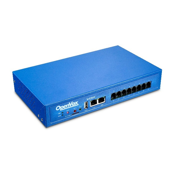
Summary of Contents for OpenVox UC501
- Page 1 OpenVox Communication Co Ltd UC501 IPPBX Quick Start...
-
Page 2: Technical Support
Information Access to data Please visit www.openvox.cn, and select the product model, get the latest support information, including datasheet and user manual. Technical Support For help, contact OpenVox Communication Co., Ltd. Technical Support: Email: support@openvox.cn Tel: +86-755-66630978 , +86-755-82535461 Fax: +86-755-83823074... -
Page 3: Packing Details
UC501 Quick Start Packing Details After unpacking, check if the contents are complete. If there are any omissions, please contact your dealer. ⚫ UC501 x 1 ⚫ Network Connection x 1 ⚫ Power Adapter x 1 ⚫ Rubber Mat x 1 ⚫... - Page 4 LED Indicator Color Status ① Power Indicator Always Green Supply Power ② System Indicator Green and Flash(1s) Work Normally Red and Flash(1s) Normal ⑩Module Indicators Always Red Connected (FXO) Red and Flash(0.1s) Communicating ⑩Module Indicators Always Green Normal (FXS) Green and Flash(0.1s) Communicating During initialization, all LED indicators will flash successively B.
-
Page 5: Install Module
Install Module After confirming the components are complete, start installing modules. 1. Unscrew the screws on both sides of the device. 2. Remove the upper casing in the direction shown in picture. - Page 6 3. Below is the top view of the inside of the chassis, and the right side is the module installation area. The upper area is for the FXO-100/FXS-100 module and the lower area is for the FXO-400/FXS-400 module. It should be noted that the module cannot be installed on the left or right side at the same time, only supports ①+②, ③+④, ①+④, ②+③.
- Page 7 Remove the screw and install the module(②+③mode). 4. After installing the module, insert the chassis vertically as the picture shows, fasten it to the upper case, and then tighten the screws.
-
Page 9: Cable Connection
① Connect the LAN port to the LAN switch using a network cable. ② Use the dedicated power cable and turn on the power, the UC501 system starts, and the power indicator is green. - Page 10 Login administrator interface 1. Connect the computer to the same network with the UC501 device; 2. Open a web browser and enter the default IP address of UC501: 172.16.101.1; 3. Use the default username(admin) and password(admin) to log in to the...
Need help?
Do you have a question about the UC501 and is the answer not in the manual?
Questions and answers