Table of Contents
Advertisement
ULTRA TEC
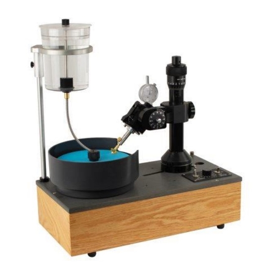
VL CLASSIC FACETING MACHINE
USER MANUAL
NOTE: Right Side Mount shown –
Left Side mount is mirror image
ULTRA TEC Manufacturing, Inc.
1025 E. Chestnut Ave, Santa Ana, CA 92701, USA
Tel: +1-714-542-0608
Fax: +1-714-542-0627
e-mail: info@ultratec-facet.com
www.ultratec-facet.com
Version 1.05 March 2020
1
Advertisement
Table of Contents

Summary of Contents for ULTRA TEC VL
- Page 1 ULTRA TEC VL CLASSIC FACETING MACHINE USER MANUAL NOTE: Right Side Mount shown – Left Side mount is mirror image ULTRA TEC Manufacturing, Inc. 1025 E. Chestnut Ave, Santa Ana, CA 92701, USA Tel: +1-714-542-0608 Fax: +1-714-542-0627 e-mail: info@ultratec-facet.com www.ultratec-facet.com...
-
Page 2: Table Of Contents
CONTROL OF FLATNESS STANDARD TOOLS AND TECHNIQUES DOP INSERTION and RETENTION THE TABLING ADAPTER 4.2.1 Tabling—some accessory choices THE TRANSFER FIXTURE MAINTAINING AND ADJUSTING YOUR ULTRA TEC THE FACETING PROCESS THE BASICS 6.1.1 SELECTING ROUGH MATERIAL LEARNING TO FACET APPENDIX 1 TABLE OF FACET ANGLES Version 1.05 March 2020... -
Page 3: Test Report And Warranty
(RMA), a completed copy of which must be included in the return-material shipment. ULTRA TEC will correct the problem by repair or replacement and return the unit to you. ULTRA TEC is not responsible or liable for unauthorized repairs, alterations, or any contingent damages. -
Page 4: Introduction
ABOUT YOUR ULTRA TEC FACETING MACHINE In using your ULTRA TEC, keep in mind that it is a precision device, capable of exceedingly fine angular and linear settings. It is, nonetheless, a rugged machine that will provide you with many years of use. Normal cleanliness with minimal care will give you many hundreds of faceted gems. -
Page 5: Unpackaging The Unit
1.0 UNPACKAGING THE UNIT The machine comes in protective packaging which you may want to save, along with its box, in the event that future shipment or storage is necessary. These are the included items: The Mast is packaged in a separate box. -Tabling Adapter, and Alignment Bar AC Adapter, Calibration Block and wrenches (if you have purchased a digital... - Page 6 Splashpan, Drip Tank The Base. To Remove the Base from the box, reach under the wood support base and lift. Anti-Splash Sponge and Clip-installed on splashguard. Version 1.05 March 2020...
-
Page 7: Setting Up
2.1 THE BASE The ULTRA TEC Base can be placed on a tabletop, or it may be mounted permanently into a workbench. For permanent mounting, the cutout dimensions are 7 7/8" by 18 1/2". As a template for the cutout, use the Wood Base—the cutout corresponds to the inside dimensions—you can trace that with a pencil... -
Page 8: The Drip Tank
When setting the Splashguard into position on the Base, be sure that the drain molded onto the Splashguard is set into the Drain Funnel in the Baseplate. To set the Splashguard in place, grip the sides of the Splashguard and push down until the Splashguard seats – to remove the Splashguard for cleaning, grip the sides and pull up. -
Page 9: The Platen
2.1.5 THE PLATEN The Platen is permanently attached to the Spindle—a sub-assembly that rides in permanently lubricated ball bearings. When a lap is placed onto the Platen, take care that the undersurface of the lap is clean and is held down by the Safety Nut. -
Page 10: The Lamp
2.1.8 THE LAMP If you have purchased a lamp, it mounts onto the stud already assembled in the base, in the corner behind the head. The lamp mounting lock has a snap-on design. Pull back the nylon ring, place the lamp onto the stud, and push down the ring. -
Page 11: The Basic Control Features Of The Faceting Mast
Loosening the Locking Knob also allows the Z-position Cylinder to rotate freely (the condition you want as the faceting proceeds). Still another function of the Locking Knob is that it binds together the several sub assemblies that make up the Mast, and when tightened –... -
Page 12: Free Rotation
3.1.1 FREE ROTATION OF THE INDEX GEAR (often called "FREE-WHEELING"--this is often used in forming a round girdle on a stone). When the Detent is retracted it can be held in its raised position – allowing free rotation of the Index Gear- by engaging the Latch (near the back of the Rocker (as shown). - Page 13 1. To change an Index Gear, first, turn in the Retention Set screw so it does not protrude above Outside diameter surface of the Quill (it’s OK – it will not fall into the inside diameter). Then, loosen the set screw in the hub of the mounted Index Gear and slide the Index Gear being removed forward and off the Quill.
-
Page 14: The Index Vernier (Cheater)
3.1.3 THE INDEX VERNIER (Cheater) The Index Vernier is for making rotational (indexing) adjustments. Each line is on the Dial is 0.1. The Index Vernier is used if there is a need to align crown facets to existing pavilion facets (after completing transfer of the stone), and, it is also used for slight adjustments when polishing (from which it gained the name of “Cheater”... -
Page 15: Verifying The 0 Position Of The Index Vernier
3.1.3.2 Verifying the 0 position of the Index Vernier It is a good idea to verify that the Index Vernier is in its 0 position before starting to facet another stone. If you suspect that the Index Vernier has been moved more than a full rotation, go back and reset 0 on the Index gear and 0 on the index Vernier, using the Alignment Bar. - Page 16 Fine Adjustment Knob (D), pointing up from the upper Yoke surface. Tightening that Lever locks the angular setting of the quill. The round central Tension Knob (C) functions as a brake - when the Knob is backed off (CCW), the quill swings down freely –...
-
Page 17: Digital Angle Dial Controls
Making this angle setting will become “automatic” for you. Practice it (it’s complicated to write this description— but performing the task quickly becomes an easy natural thing to do). 7) Positioning the stone onto the Lap. Loosen the Collar-Locking Knob so that lateral swing is easy. Set the stone above the Lap, and, loosening the Carriage Knob, gradually lower the stone position, sliding down the Z- position Cylinder, toward the Lap surface –... -
Page 18: Control Of Height-Vertical Positioning
– to about 1.5 on the calibrated scale. 3.4 CONTROL OF FLATNESS This control is built into your ULTRA TEC. The surface runout of the Platen is less than .0003 of an inch. (less than 8 microns). Laps are manufactured to be suitably flat, but their accuracies vary, and all laps have some degree of error. -
Page 19: Standard Tools And Techniques
4.0 STANDARD TOOLS AND TECHNIQUES Other than controls, there are these important "how-to's in using the machine: Inserting and holding the Dop, using the Tabling Adapter, using the Transfer Fixture: DOP INSERTION and RETENTION Dops are keyed so that they can be removed and reinserted – to the same depth and same rotary position. The back end of the Dop has a 45-degree angle chamfer (see note 1, below). -
Page 20: The Tabling Adapter
4.2 THE TABLING ADAPTER. Used to work on the table of the gem, it points the dopped gem straight down at the lap (it's often called a "45 Adapter", since, when it is used, the axial angle is set at 45). To assemble the Tabling Adapter to the Quill, turn in the Retention Set Screw so that there is no extension of it above the Quill’s outer surface. -
Page 21: Maintaining And Adjusting Your Ultra Tec
5.0 MAINTAINING AND ADJUSTING YOUR ULTRA TEC ● Your ULTRA TEC should be covered when not in use or stored in a clean place. ● All bearings are lubricated and sealed. It is not necessary to lubricate bearings. ● It is a good idea to lubricate the Dovetail occasionally. Use a tissue to clean the dovetail, and then apply a light film of grease. -
Page 22: The Faceting Process
The higher the mesh number, the finer the particle size. For initial grinding – shaping of the stone – 260 mesh Laps are commonly used – although Ultra Tec recommends that 360 mesh be the coarsest Lap used –... -
Page 23: Learning To Facet
And of course, there is the basic start-out how-to information that is in this Owner's Manual. Also, keep your eye on the ULTRA TEC Website (www.ultratec-facet.com). And not least--think about joining one of the several Faceting Guilds—even if you cannot go to their meetings, their newsletters are valuable. - Page 24 6.2.2 THE FIRST CUT – A PRELIMINARY TABLE Having determined where the table should be, hold the stone in your fingers and using a 360 grit lap (or a 600 Lap if that’s coarse enough to remove the material you want to remove), grind a "preliminary" table--you need a surface large enough for attaching the dop.
- Page 25 6.2.4 CUTTING THE GIRDLE On this step, and the ones that follow, we refer to diamond plated laps as “coarse” (360 mesh) or “medium” (600-1200 mesh). Use the coarse lap where you are removing a considerable amount of material, and switch to the medium lap to finish shaping the stone. In general—on large stones there’s a lot of work to do with the coarse lap, and on small stones, hardly any (you will quickly learn which lap is appropriate).
- Page 26 6.2.5 SHAPING THE PAVILION – BREAK FACETS Now, the pavilion can be formed – the Break Facets are done first. You are still using the coarse lap, (switch to a medium lap as you approach the target angle—or, use a medium lap all the way— it’s not so slow).
- Page 27 6.2.7 PRE-POLISH The pre-polish lap is used (for example, a BATT Lap), with a 3000 diamond compound. You repeat the sequence of the prior steps. Examine the facet surfaces – it should be starting to look good.. Let’s move directly to the final polish step. 6.2.8 POLISHING THE PAVILION The technique of polishing that is recommended here is the use of Ultra Laps (these laps have the polishing medium deposited on a mylar film).
- Page 28 6.2.9 TRANSFERRING Read the section on the Transfer Fixture which explains how the dops are set into the fixture. In setting the dops into the fixture, see that the key (chamfer) on the dops are firm against the edge of the pushers", aligning the dops radially.
- Page 29 6.2.12 CROWN MAIN FACETS Again, proceed cautiously and inspect often. Main facets – set Angle Dial at 40 degrees 96 Index at: 96 (0),12, 24, 36, 48, 60, 72, 84 Cut the Main Facets so that they meet at points along the girdle.
-
Page 30: Appendix 1 Table Of Facet Angles
APPENDIX 1 TABLE OF FACET ANGLES We thank Louis Roth for this table. Lou comments: The cutting angles in this chart represent opinions, round- offs, and compromises, so please use it as a “handy guide” and not Gospel. If you see errors, or learn some later information, we’d appreciate your communicating with us.
Need help?
Do you have a question about the VL and is the answer not in the manual?
Questions and answers