Table of Contents
Advertisement
Quick Links
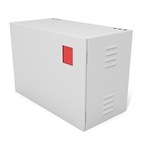
UL924 LISTED
EMERGENCY LIGHTING
EQUIPMENT
IMPORTANT SAFEGUARDS:
READ AND FOLLOW ALL SAFETY INSTRUCTIONS
When using electrical equipment, basic safety precautions
should always be followed, including the following:
1. Do not install outdoors.
2. Do not install near gas or electric heaters.
3. Mount CEPS-A securely and in locations and at heights where it will not be readily subjected
to tampering by unauthorized personnel.
4. Do not use this equipment for other than its intended use.
5. All installation and servicing of this equpiment must be performed by qualified personnel.
6. The use of accessory equipment not specified or recommended by LVS, Inc. may cause
unsafe conditions and may void the warranty.
7. Use caution when servicing batteries. Battery acid can cause burns to skin and eyes. If acid is
spilled on skin or in the eyes, flush with fresh water and seek medical attention immediately.
8. Make sure all connections are in accordance with NEC and local regulations.
9. Check AC Voltage rating on equipment label. Do not connect to any other voltage.
10. An unswitched AC power source is required (120 VAC or 277 VAC).
11. Do not use this product for other than intended use.
12. To reduce risk of electric shock, disconnect dedicated input breaker and all fuses before servicing.
13. Do not attempt to service sealed components with the exception of standard battery replacements.
U L
®
73PK
SAVE THESE INSTRUCTIONS
LVS, Inc. 2555 Nicholson Street, San Leandro, CA 94577-4216
Phone: 510-352-9600
www.lvscontrols.com
Model CEPS-A
Installation Instructions
& User Manual
500W-6000W
Emergency
Lighting Inverter
1-800-982-4587 Fax:
510-352-6707
Advertisement
Table of Contents

Related Manuals for LVS CEPS-A

Summary of Contents for LVS CEPS-A
- Page 1 1. Do not install outdoors. 2. Do not install near gas or electric heaters. 3. Mount CEPS-A securely and in locations and at heights where it will not be readily subjected to tampering by unauthorized personnel. 4. Do not use this equipment for other than its intended use.
- Page 2 Where applicable law prohibits disclaimers or the implied warranties of merchantability and fitness; those warranties are limited to 12 months from date of shipment. LVS does provide a 90 day money back guarantee if equipment does not perform in accordance with LVS published specifications. The liability of LVS and its agents under all warranties is limited to repair and replacement as described herein, and under no circumstances shall there be liability for any other kind of loss, damage, or labor, either consequential or for injury to person or property or otherwise.
- Page 3 9) Ensure all connections & grounding have been made in workman-like & code compliant manner. NOTE: The CEPS-A can be field-wired in 3 distinct modes of operation. See “WIRING MODES” i n s e r t sheet for further details.
- Page 4 Battery Installation 1. Remove batteries from shipping boxes and check for enclosure and terminal damage. 2. Batteries should have labels and jumper wires installed. l l a connections prior to battery connections. 4. Check all batteries for proper color connectors: TYPE “A”...
- Page 5 XFR B Leads XFR B Leads #3 (blue) Transfer Switch (red box) #4 (white with blue stripe) Ground Stud ® LVS, Inc. 2555 Nicholson Street, San Leandro, CA 94577-4216 UL924 LISTED Phone: 510-352-9600 1-800-982-4587 Fax: 510-352-6707 EMERGENCY LIGHTING EQUIPMENT www.lvscontrols.com 73PK...
- Page 6 The wiring of the #1 wire on the transfer switch (red plastic box) normal condition. #1) (DEFAULT) NORMALLY-ON: CONNECT #1 TO INPUT HOT The emergency lights connected to the CEPS-A will be Neutral ON at all times, during normal condition (24/7) and power interruptions. ...
- Page 7 CEPS-A GFCI Troubleshooting If the GFCI on the blue inverter is tripping, there are two things that can cause this: a crossed neutral (dangerous) or inrush current (not dangerous). This simple test will help you to determine which it is.
- Page 8 Note: The reset switch for the blue inverter is on the back right side of the inverter. It is a 3 position rocker switch. You can reach it by reaching around the black cord through the opening in the metal side bracket and pressing the switch to the middle(OFF) position, wait 5 seconds, then turn it back down (ON).
Need help?
Do you have a question about the CEPS-A and is the answer not in the manual?
Questions and answers
I need to know what the dip switches are supposed to be on the transfer switch