Table of Contents
Advertisement
Advertisement
Table of Contents

Summary of Contents for Evoqua WALLACE & TIERNAN DEPOLOX POOL E
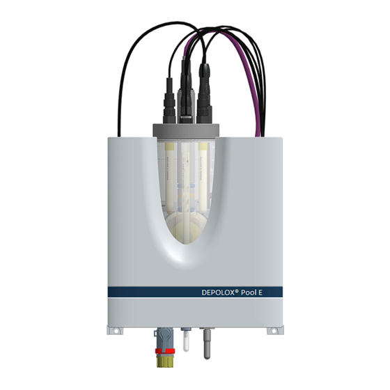
- Page 1 ® DEPOLOX POOL E ® WALLACE & TIERNAN FLOW CELL INSTRUCTION MANUAL...
- Page 2 Translation of the original instruction. In some countries, DEPOLOX, OSEC, Barrier, Chem-Ad and Wallace & Tiernan are trademarks of Evoqua, its subsidiaries or affiliated companies. No part of this document may be reproduced in any form (printed, photocopy, microfilm, or any other procedure) or saved, processed, copied, or distributed using electronic data systems - without the express prior written con- sent of Evoqua Water Technologies GmbH.
-
Page 3: Table Of Contents
DEPOLOX® Pool E flow cell Contents Contents Introduction ................5 Target groups ......................5 Structure of the documentation ................5 Conventions......................5 Safety..................6 Intended use......................6 General safety instructions ..................6 Specific operating phases..................7 Warranty conditions....................7 Exclusion of liability ....................7 Description................. 8 Version ........................8 Configuration options....................10 Spare Parts/extensions..................11 Optional accessories....................11... - Page 4 Contents DEPOLOX® Pool E flow cell Maintenance................32 Maintenance intervals ..................32 Maintenance parts set ..................32 Checking for leakage..................... 32 Checking and replacing the electrode cleaning sand..........33 Checking and replacing the fine filter ..............33 Cleaning the flow rate monitor and check valve ..........33 Cleaning or replacing the optional strainer ............
-
Page 5: Introduction
DEPOLOX® Pool E flow cell 1. Introduction Introduction WARNING Electrocution hazard. Target groups This instruction manual provides the informa- tion required for installation, operating and ATTENTION maintenance personnel for the installation, Environmental hazard! operation and maintenance of the DEPOLOX® Do not throw away or burn the batteries! Pool E flow cell. -
Page 6: Safety
2. Safety DEPOLOX® Pool E flow cell Safety State-of-the-art technology The flow cell has been constructed in accor- dance with the technological state-of-the-art Intended use and the accepted rules of safety engineering. The DEPOLOX® Pool E flow cell in combination However, if the flow cell is used by persons with the installed sensors and 700 P electro- who have not been adequately instructed,... -
Page 7: Specific Operating Phases
DEPOLOX® Pool E flow cell 2. Safety Warranty conditions IT security The manufacturer offers IT security mecha- The following must be observed for compli- nisms for its products to support secure sys- ance with warranty conditions. If any of the tem operation. -
Page 8: Description
3. Description DEPOLOX® Pool E flow cell Description DFMe electronics module converts the analog sensor signals for digital transmission to 700 P electronics module. If a total chlorine memb- The DEPOLOX® Pool E flow cell (module type rane sensor TC3 CAN (optional) is used, this is D01) is part of the Pool Management System connected directly to DFMe electronics DEPOLOX®... - Page 9 DEPOLOX® Pool E flow cell 3. Description Example C P M N L B DE O O Selection of sensor measuring module for free chlorine Sensor measuring module DEPOLOX® Pool E Sensor measuring module DEPOLOX® 5 E Selection of sensor measuring module for pH value Sensor measuring module pH value No sensor measuring module pH value Selection of sensor measuring module for...
-
Page 10: Configuration Options
3. Description DEPOLOX® Pool E flow cell Configuration options DEPOLOX® Pool E flow cell pressurized version Designation non-pressurized pressurized with cell body version version cover W3T417269 (optional) A Chlorine sensor (free chlorine) B Total chlorine membrane sensor TC3 CAN Conductivity sensor D ORP (Redox) single-rod measuring chain LED glow stick pH single-rod measuring chain... -
Page 11: Spare Parts/Extensions
DEPOLOX® Pool E flow cell 3. Description Spare Parts/extensions Flow cell Part No. Designation 3.5.1 Design Sensor measuring module W3T320090* DFMe Total chlorine TC3 CAN Cell body cover, fully pressu- W3T417269* rized version Sensor measuring module W3T320088 DFMe pH Sensor measuring module W3T320089 DFMe ORP (Redox) Sensor measuring module... -
Page 12: Dfme Electronics Module
3. Description DEPOLOX® Pool E flow cell 3.5.2 Function The flow distributor cap screwed into the cell body from the bottom enables the continuous The sample water is connected on the input hydromechanical cleaning of the electrode of side to the shut-off ball valve via the G1/2" the chlorine sensor using special cleaning sand connection. -
Page 13: Module Sidisens Conductivity (Optional)
DEPOLOX® Pool E flow cell 3. Description Module SiDiSens conductivity Sensors (optional) The DEPOLOX® Pool E flow cell (module type D01) can optionally be equipped with the fol- To measure the conductivity, conductivity lowing sensors: module SiDiSens LF (optional) is installed in DEPOLOX®... - Page 14 3. Description DEPOLOX® Pool E flow cell 3.9.2 DFMe electronics module Sensor electronics integrated in the flow cell for connection of Version Chlorine sensor und multi-sensor; 2 slots for sensor modules pH and ORP (Redox) Power supply 24 V DC 5-pole M12 socket for CAN interface and 24 V DC supply;...
- Page 15 DEPOLOX® Pool E flow cell 3. Description 3.9.4 Sensors NOTICE When disinfecting inline electrolysis systems, the gold version of the chlorine sensor or the ORP (Redox) single-rod measuring chain must be used. Chlorine sensor Platinum version (W3T160652) Gold version (W3T160991) Amperometric 3-electrode Amperometric 3-electrode sensor with platinum...
- Page 16 3. Description DEPOLOX® Pool E flow cell pH single-rod measuring chain (W3T169297) Single-rod measuring chain with universal membrane glass, Version salt reserve, zirconium dioxide diaphragm, polymerized solid electrolyte, Ag/AgCl drain system Measurement range pH 0 to 12 (temporarily to pH 14) Working temperature -5 to +80°C (23 to 176°F) range...
-
Page 17: Installation
DEPOLOX® Pool E flow cell 4. Installation Installation Shut-down The flow cell may only be taken out of opera- tion by trained and authorized personnel. Scope of delivery Required ambient conditions NOTICE The DEPOLOX® Pool E flow cell (module type NOTICE D01) is configured in the factory according to Correct and safe operation can only be gua-... -
Page 18: Installation Of The Module
4. Installation DEPOLOX® Pool E flow cell Installation of the module NOTICE Install the electronics module and flow cell • The electronics module is not suitable with or without DIN rail. Dimension drawing for electrical connection with perman- chapter 4.5.3. ently installed cable conduits. - Page 19 DEPOLOX® Pool E flow cell 4. Installation 4.5.3 Dimension drawing DEPOLOX® Pool E flow cell (non-pressurized version) and electronics module...
- Page 20 4. Installation DEPOLOX® Pool E flow cell DEPOLOX® Pool E flow cell (pressurized version) and electronics module...
-
Page 21: Removing And Fitting The Housing Cover
DEPOLOX® Pool E flow cell 4. Installation Removing and fitting the Connecting the sample water housing cover inlet When connecting the sample water inlet, note Removing the following: • Remove the housing cover of the flow cell. To do this, press both unlocking but- •... -
Page 22: Connecting The Sample Water Outlet
4. Installation DEPOLOX® Pool E flow cell 4.8.1 With tubing connection • The sample water outlet must be laid in such a way as to prevent siphoning. NOTICE The water-tightness of the hose screw con- 4.9.2 Pressurized version nection is only guaranteed if the following When connecting the sample water outlet, installation instructions are followed! note the following:... - Page 23 DEPOLOX® Pool E flow cell 4. Installation Example for sample water extraction - Part list on page 22...
- Page 24 4. Installation DEPOLOX® Pool E flow cell Example for sample water extraction using a booster pump...
-
Page 25: Installing The Fine Filter
DEPOLOX® Pool E flow cell 4. Installation 4.11 Installing the fine filter 4.12 Inserting or replacing electrode cleaning sand NOTICE The electrode cleaning sand (W3T171317) is A fine filter must only be installed when supplied in a plastic bottle, the cap serves as a membrane sensors are employed. -
Page 26: Plugging Sensors Into The Dfme Electronics Module
4. Installation DEPOLOX® Pool E flow cell Screw the flow distributor cap back on. 10 Open the shut-off ball valve on the sam- ple water inlet and outlet. The cell body fills with sample water again. 11 Refit the housing cover of the flow cell. 12 After 2 to 3 hours running-in time, per- form a chlorine calibration. -
Page 27: Fitting The Sensors
DEPOLOX® Pool E flow cell 4. Installation 4.14 Fitting the sensors Depending on requirements, insert or screw in the sensors into the mount hole on the cover NOTICE of the cell body. • With the pressurized version, the sen- Remove the plug from the mount hole on sors must be screwed in or secured to the cover of the cell body. -
Page 28: Startup
4. Installation DEPOLOX® Pool E flow cell 4.16 Startup 4.17 Shut-down DANGER DANGER Risk of injury or death! Risk of injury or death! The DEPOLOX® Pool E flow cell must not be External voltages may still be connected operated with flammable liquids. even if the operating voltage is switched off. -
Page 29: Renewed Start Up
DEPOLOX® Pool E flow cell 4. Installation 10 Refit the housing cover. Take out all sensors from the mounting hole in the cell body cover and unplug the cable gland from DFMe electronics module. Hold the cable while doing this as it must not be allowed to twist. - Page 30 4. Installation DEPOLOX® Pool E flow cell 11 Fit the housing cover of DFMe electronics 15 The membrane sensor is connected either module and secure with the four cover at the CAN socket (C - Fig. 14) on conduc- screws. Tighten hand-tight the housing tivity module SiDiSens connected directly screws (to a maximum torque of 0.7 Nm via the CAN extension socket (C - Fig.
- Page 31 DEPOLOX® Pool E flow cell 4. Installation 4.19.2 Replace standard cell body cover (optional) The pressurized version can be retrofitted with the total chlorine membrane sensor TC3 CAN. Please note that the standard cell body cover must be replaced by an optional cell body cover (W3T417269).
-
Page 32: Maintenance
5. Maintenance DEPOLOX® Pool E flow cell Maintenance Maintenance parts set DANGER 5.2.1 Non-pressurized version Risk of injury or death! Part No. Designation External voltages may still be connected even if the operating voltage is switched off. Maintenance parts kit, W3T166181 annual maintenance NOTICE... -
Page 33: Checking And Replacing The Electrode Cleaning Sand
DEPOLOX® Pool E flow cell 5. Maintenance Checking and replacing the electrode cleaning sand The electrode cleaning sand is necessary for cleaning the chlorine sensor and must be replenished or replaced if necessary. The elec- trode cleaning sand must be checked and replaced regularly (chapter 4.12). -
Page 34: Cleaning Or Replacing The Optional Strainer
5. Maintenance DEPOLOX® Pool E flow cell Cleaning or replacing the 11 Check that the check valve housing is cor- rectly positioned by the guide lugs on the optional strainer housing. The optional strainer must be cleaned or 12 Fit the filter unit again. To do this, tighten replaced regularly to avoid contamination or the knurled nuts. -
Page 35: Spare Parts, Accessories And Retrofit Kits
DEPOLOX® Pool E flow cell 6. Spare parts, Accessories and Retrofit kits Spare parts, Accessories and Retrofit kits NOTICE For reasons of safety, only use original spare parts. Please contact our customer service if you need any spare parts. Cell body, DEPOLOX® Pool E flow cell Item 1 Item 2 Item 4... -
Page 36: Depolox® Pool E Flow Cell - Non-Pressurized Version
6. Spare parts, Accessories and Retrofit kits DEPOLOX® Pool E flow cell DEPOLOX® Pool E flow cell - non-pressurized version DEPOLOX® Pool E flow cell - non-pressurized version (module name D01) - W3T350213 Item Part No. Designation Item Part No. Designation W3T166160 EPDM flat gasket... - Page 37 DEPOLOX® Pool E flow cell 6. Spare parts, Accessories and Retrofit kits...
-
Page 38: Depolox® Pool E Flow Cell - Pressurized Version
6. Spare parts, Accessories and Retrofit kits DEPOLOX® Pool E flow cell DEPOLOX® Pool E flow cell - pressurized version DEPOLOX® Pool E flow cell - pressurized version (module name D01) - W3T350214 Item Part No. Designation Item Part No. Designation W3T172556 O-ring... - Page 39 DEPOLOX® Pool E flow cell 6. Spare parts, Accessories and Retrofit kits...
-
Page 40: Dfme Electronics Module
6. Spare parts, Accessories and Retrofit kits DEPOLOX® Pool E flow cell DFMe electronics module Multisens BZ-1569_003 Item Part No. Desciption DFMe electronics module W3T320004 comprising: basic housing DFMe, DFMe Board DES and DFMe connection W3T262803 Basic housing DFMe W3T256343 Housing cover DFMe W2T807967 Plastic self-tapping screw A2 W3T320085 Spare PCB, DFMe board DES W2T504397 Plastic self-tapping screw d4x10... -
Page 41: Sensors
DEPOLOX® Pool E flow cell 6. Spare parts, Accessories and Retrofit kits Sensors NOTICE When disinfecting the inline electrolysis systems, the chlorine sensor and ORP (Redox) single- rod measuring chain must be used, gold version (gold electrode). pH single- ORP (Redox) Chlorine single-rod Conductivity... -
Page 42: Membrane Sensor
6. Spare parts, Accessories and Retrofit kits DEPOLOX® Pool E flow cell Membrane sensor Part No. Designation W3T391563 Total chlorine membrane sensor TC3 CAN W3T391564 Plastic membrane cap TC3 for use in total chlorine membrane sensor TC3 CAN. Notice: Please use at increased salt concentration (optional)! W3T437804 CAN bus extension cable 1 m for total chlorine membrane sensor W3T164339 Spare parts kit (incl. -
Page 43: Accessories
DEPOLOX® Pool E flow cell 6. Spare parts, Accessories and Retrofit kits 6.10 Accessories Part No. Designation W3T158721 Strainer with ball valve, straight W3T389201 Set of fittings for strainer Metric PVC tubing, fabric-reinforced ø 4 x 3 ø 6 x 3 ø... -
Page 44: Ec Declaration Of Conformity And Certificate
7. EC Declaration of Conformity and Certificate DEPOLOX® Pool E flow cell EC Declaration of Conformity and Certificate... - Page 45 DEPOLOX® Pool E flow cell 7. EC Declaration of Conformity and Certificate...
- Page 46 70138021 2017-07-14 Project: Date Issued: Issued to: Evoqua Water Technologies GmbH Auf der Weide 10 Gunzburg, 89312 GERMANY The products listed below are eligible to bear the CSA Mark shown with adjacent indicators 'C' and 'US' for Canada and US or with adjacent indicator 'US' for US only or without either indicator for Canada only.
- Page 47 DEPOLOX® Pool E flow cell Wallace & Tiernan® Products worldwide Australia Canada China +61 1300 661 809 +1 905 944 2800 +86 21 5118 3777 info.au@evoqua.com wtoe.can@evoqua.com sales.cn@evoqua.com France Germany Singapore +33 1 41 15 92 20 +49 8221 9040 +65 6559 2600 wtfra@evoqua.com...
- Page 48 © 2020 Evoqua Water Technologies GmbH Subject to modifications WT.050.810.020.DE.IM.0420 W3T321499 Issue 12-0420 Auf der Weide 10, 89312 Günzburg, Germany +49 (8221) 904-0 www.evoqua.com...
Need help?
Do you have a question about the WALLACE & TIERNAN DEPOLOX POOL E and is the answer not in the manual?
Questions and answers