
Related Manuals for Mannesmann Rexroth Indramat DDC Series

Summary of Contents for Mannesmann Rexroth Indramat DDC Series
- Page 1 engineering mannesmann Rexroth DDC and MDD Digital Intelligent AC Servo Drives with Single Axis Positioning Module Application Manual DOK-CONTRL-DDC+MDD+DLC-ANW1-EN-P Indramat 271433...
- Page 2 About this documentation Title DDC and MDD Digital Intelligent AC Servo Drives with Single Axis Positioning Module Type of documentation Applications Manual Document code DOK-CONTRL-DDC+MDD+DLC-ANW1-EN-E1,44 Internal file reference • Mappe13 • DDC01-AN.pdf • 209-0069-4393-00 Reference This electronic document is based on the hardcopy document with docu- ment desig.: DOK-CONTRL-DDC+MDD+DLC-ANW1-EN-P •...
-
Page 3: Table Of Contents
Table of Contents Table of Contents Page Introducing the System 1.1. Types of Digital Drives ..............8 Components of Digital AC Servo drives with a DLC Single-Axis Positioning Module 2.1. Basic Unit ..................12 2.2. DLC 1.1 Single-Axis Positioning Module ........12 2.3. - Page 4 Table of Contents Parameter Input 6.1. Parameter Input Aids ..............39 6.2. Using the CTA to Input Parameters ..........40 6.3. Parameter Input Preparations ............41 6.4. Inputting Parameters ..............42 6.5. Explanatory Notes on Several Important DLC Parameters ... 44 6.6.
- Page 5 Table of Contents 8.9. Automatic Mode ................87 Diagnostics and Fault Clearance 9.1. Operating Status Display of the Drive Controller ......91 9.2. Fault Displays of the Drive Controller ..........92 9.3. Diagnostics Possibilities with a CTA Programming and Display Unit .................. 101 9.4.
- Page 6 Table of Contents • DOK-CONTRL-DDC+MDD+DLC-ANW1-EN-E1,44 • 01.97...
-
Page 7: Introducing The System
1. Introducing the System Introducing the System Digital AC Drives Digital AC drives are microprocessor controlled, brushless, three-phase cur- rent drives with high dynamics and precise servo drive features. The entire scope of • drive control, • monitoring, • parametrization and •... -
Page 8: Types Of Digital Drives
1. Introducing the System The DLC 1.1 single-axis positioning module offers the following features: • A user-oriented programming language. • Easy input of up to 3,000 program blocks, e.g., position and speed ent- ries, input queries, output settings and markers for control and motion sequences. - Page 9 1. Introducing the System Mounting directly to the INDRAMAT drive controllers with integral DLC single-axis positioning forward feed unit moudle have been especially designed for the requirements of complex finishing facilities, e.g., transfer systems. The drive controllers with protection category IP 65 can be directly installed to the forward forward feed unit.
-
Page 10: Components Of Digital Ac Servo Drives With A Dlc Single-Axis Positioning Module
2. Components of Digital AC Servo drives with a DLC Single-Axis Positioning Components of Digital AC Servo drives with a DLC Single-Axis Positioning Module Components of digital AC servo drives with DDC 1.1 and DLC Configured single-axis positioning DDC 1.1 drive module Configuration... - Page 11 2. Components of Digital AC Servo drives with a DLC Single-Axis Positioning A configured drive controller is made up the following components: • the basic unit • a DLC single-axis positioning module • the software module • an optional auxiliary plug-in module •...
-
Page 12: Basic Unit
2. Components of Digital AC Servo drives with a DLC Single-Axis Positioning 2.1. Basic Unit The basic unit is made up of a DC bus rectifier, the bleeder resistor for taking up the energy generated during braking and a mains section for the control voltages. -
Page 13: Software Module
2. Components of Digital AC Servo drives with a DLC Single-Axis Positioning 2.3. Software Module Parameters, stored in the software module, are implemented for matching the drive controller to the motor and the mechanical system of the machine. Barcode Software version Serial number DSM 2.1 DSM 2.1-C11-01RS... -
Page 14: Auxiliary Plug-In Cards
2. Components of Digital AC Servo drives with a DLC Single-Axis Positioning 2.4. Auxiliary Plug-In Cards The following plug-in cards have been summarized under the heading of "Auxiliary Plug-In Cards". Input/output interfaces Type: DEA 4.1, DEA 5.1 and DEA 6.1 These plug-in modules each have 15 inputs and 16 outputs with which the drive can exchange binary signals. - Page 15 2. Components of Digital AC Servo drives with a DLC Single-Axis Positioning Only those configurations specified by INDRAMAT may be used. The configuration rating plate lists those modules which can be used with a specific drive. Prior to commissioning a drive, make sure that the one specified on the rating plate is the one that is actually in use in this case.
-
Page 16: Digital Ac Servo Motors
2. Components of Digital AC Servo drives with a DLC Single-Axis Positioning 2.6. Digital AC Servo Motors Side A Side B feedback FAMD112 Fig 2.9: An MDD motor The digital MDD AC servo motors are available in the following feedback versions: •... - Page 17 2. Components of Digital AC Servo drives with a DLC Single-Axis Positioning MDD motor type codes Example: M D D 11 2 B - N - 0 1 5 - N 2 L - 1 3 0 G B 0 1.
-
Page 18: Mounting And Assembly
3. Mounting and Assembly Mounting and Assembly 3.1. Mounting the drive Directly to the forward A DDC 1 drive has a protection category of IP 65 and can be directly moun- feed unit ted to the forward feed unit. Cooling The units must be mounted in such a way that the flow of the cooling air is not prevented from either entering or exiting the machine. -
Page 19: Power Connections Of The Ddc
3. Mounting and Assembly 3.2. Power connections of the DDC The power connectors of the DDC (X7), the motor power connector (X5) and the interface to the machine control (X8) on the DDC must be IP 65 connec- tors. The motor feedback cable and the connections of the optional plug-in modu- les are inserted into the DDC. -
Page 20: Ddc - Dimensional Data
3. Mounting and Assembly 3.3. DDC - dimensional data inlet inlet Interface to Interface to machine machine controller controller Mains conn. Motor power 27.5 connection MBDDC Fig 3.3: Dimensional data - DDC 1.1 • DOK-CONTRL-DDC+MDD+DLC-ANW1-EN-E1,44 • 01.97... -
Page 21: Frontal View - Ddc 1
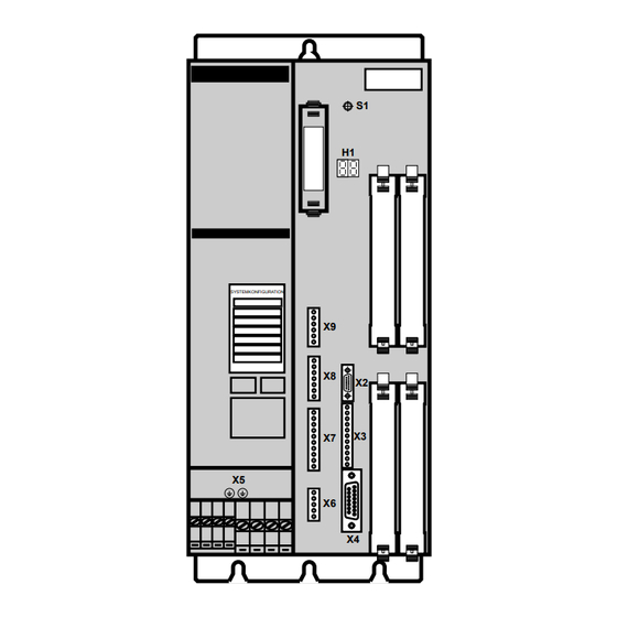
3. Mounting and Assembly 3.4. Frontal view - DDC 1 Fault reset key (S1) Slot for SYSTEMKONFIGURATION software module (U5) Status display, warning and error signals (H1) Configuration rating plate Basic unit rating plate RS-232 interface connection for VT-100 Slot for terminal command or PC (X2) -
Page 22: Coupling The Feed Motor To The Machine
3. Mounting and Assembly 3.5. Coupling the Feed Motor to the Machine Radial and axial There must always be sufficient radial and axial compensation in relati- compensation onship to all other machine parts. Coupling with a A recirculating ball screw should preferrably be coupled via a toothed belt toothed belt reduction gear with a mounted overhung toothed lock washer. -
Page 23: Electrical Connections
4. Electrical Connections Electrical Connections INDRAMAT drive controllers with integral single-axis positioning module DLC have been specifically designed to meet the extensive demands of such machines and facilities as transfer facilities, sequential finishing devices and so on. The drives with protection category IP 65 can be directly installed on the for- ward feed unit. - Page 24 4. Electrical Connections One feature of both the single-axis positioning module and the drive is their considerable insusceptibility to systems and circuitry interference. Some guidelines must, nonetheless, be observed during installation to avoid, to the greatest possible extent, the affects of interference. Avoid coupling in •...
-
Page 25: Terminal Diagram - Ddc 1.1
4. Electrical Connections 4.1. Terminal diagram - DDC 1.1 Optional interface module connection per the relevant terminal diagrams. RS 232 interface 0V M 0V M Analogue diagnostics 0V M outputs Signal voltages +24V for measuring and test purposes -15V +15V BN 1 2 Control of power... -
Page 26: Controlling The Mains Contactor
4. Electrical Connections 4.2. Controlling the Mains Contactor Application • If a synchronous motor, for example an MDD, is mounted to the DDC. Features DC bus dynamic braking always bring synchronous motors to a standstill regardless of whether the electronics of the drive are still functional or not. The DC bus dynamic brake is only applied when there is a problem in the drive. - Page 27 4. Electrical Connections DDC control • with DC bus dynamic brake • if E-Stop relay is used 3 x AC (50-60Hz) DST autotransformer 3 x AC 230V Bridge if no DC bus dynamic brake is present (see DDC Proj. Plan. Manual) X8/15 DC 24V X8/7...
-
Page 28: Dlc 1.1 Single-Axis Positioning Module
4. Electrical Connections 4.3. DLC 1.1 Single-Axis Positioning Module Ready-made cable IKS 745/... Programming and display unit RS 232 RS 485 +(Rx-TxD) 300R -(Rx-TxD) Looking onto front panel 9-pin D-SUB connector IN 525 APDLC Part no. 259 759 Fig 4.5: DLC 1.1 - terminal connecting plan •... - Page 29 4. Electrical Connections Cross-linking drive controllers via the RS 485 Drive controllers Station 1 Station 2 . . . Station 32 RS 485 SYSTEMKONFIGURATION SYSTEMKONFIGURATION SYSTEMKONFIGURATION RS 232 RS 485 RS 485 DLC 1.1 DLC 1.1 DLC 1.1 Ready-made cable Ready-made cable Ready-made cable IKB 0001...
-
Page 30: Dea 4.1, Dea 5.1 And Dea 6.1 Input/Output Interfaces
4. Electrical Connections 4.4. DEA 4.1, DEA 5.1 and DEA 6.1 Input/Output Interfaces Plant controller (e.g., PLC) 15 inputs per ea. DEA Digital Drives 16 outputs per ea. DEA SYSTEMKONFIGURATION (e.g., DKS, DDC and DDS) Ready-made cable IKS 123 X17/X32/X33 IN 0 Parameter BKGN... - Page 31 4. Electrical Connections Technical data Designation Unit min. typical max. DEA 4.1, DEA 5.1, Supply voltage DEA 6.1, Current consumption 0.15 Inputs X17/1…15 High < 1 Outputs X17/16…31 High 1) Current consumption of 0.2 A without load at outputs of 24 V 2) Current consumption of 2.2 A loading all outputs with 100 mA ea.
-
Page 32: Positioning Interface For Def 1.1 And Def
4. Electrical Connections 4.5. Positioning Interface for DEF 1.1 and DEF 2.1 Square-Wave Signals Incremental encoder max. cable length 75 m SYSTEMKONFIGURATION Linear scale Digital Drive (e.g., DKS, DDC, DDS) Connector allocation of the postion interfaces for square-wave signals DEF 1.1 = X 22 DEF 2.1 = X 24 Cable (2x1.0 + 4x2x0.25)C type: IN 209... - Page 33 4. Electrical Connections Voltage source of the typic./ Designation Unit min. max. external measuring value system Output voltage +5 V 4.75 5.25 Output current of the +5 V Voltage level and typic./ Designation Unit min. max. value phase angle of the input signals Signal voltage High...
-
Page 34: Interbus S Connection
4. Electrical Connections 4.6. INTERBUS S Connection 0 V ext A B C D INTERBUS-S Diagnosis X 39 DO 1 Inputs DI 1 E 1 Event GND 1 E 2 Reference cam free E 3 Lift brake INTERBUS-S free E 4 E-Stop coming /DO 1 INTERBUS-S... - Page 35 4. Electrical Connections Interconnecting with INTERBUS-S SYSTEMKONFIGURATION Master connection of PLC with INTERBUS-S SYSTEMKONFIGURATION SYSTEMKONFIGURATION DBS 2.X DBS 2.X Master connection DO 1 DO 1 DI 1 DI 1 GND 1 GND 1 GND 1 free free free +5 V free free /DO 1...
-
Page 36: Start-Up Aids
5. Start-Up Aids Start-Up Aids 5.1. Minimum Equipment The DLC single-axis positioning module and the drive controller can be parametrized with the use of a CTA programming and display unit. A multi- meter is needed for measuring and test purposes. The selection data manual „DDC with MDD“... -
Page 37: Recommended Equipment For Service And Start-Ups Of Dlc Single-Axis Positioning Modules
5. Start-Up Aids 5.3. Recommended Equipment for Service and Start- Ups of DLC Single-Axis Positioning Modules Interface Switch Box The following functions can be performed with the ISB-3. ISB-3 • Parametrization and diagnoses via the CTA • Drive messages (Bb, UD, BVW) can be queried via the LED. •... -
Page 38: Connecting The Start-Up Aids
5. Start-Up Aids 9-pin D-subminiature SYSTEMKONFIGURATION bushing X 31 SGND SGND serial interface: DDC 1.1 IKS046 V24, RS 232C max. 15 m long SBSerDDC Fig 5.3: Connector assignment of the RS232 interface of the DLC 5.4. Connecting the Start-Up Aids SYSTEMKONFIGURATION (optional) IN 391... -
Page 39: Parameter Input
6. Parameter Input Parameter Input 6.1. Parameter Input Aids Motion Manager Using the editor and communications program „Motion Manager“ it is possi- ble to input and secure the DLC control parameters, e.g., feed constants, amplification of position control and so on. DDS2PC It is possible to access the user interface of the drive with the DDS2PC. -
Page 40: Using The Cta To Input Parameters
6. Parameter Input 6.2. Using the CTA to Input Parameters Liquid crystal display (LCD) 4 lines with 16 places each Front panel Keypad FACTA Fig 6.1: The CTA - a programming and diagnostics unit Keyboard Functions Input of program or parameter data 1. -
Page 41: Parameter Input Preparations
6. Parameter Input 6.3. Parameter Input Preparations Applying distribution The distribution voltage must be applied to the drive controller for inputting voltage parameters. 3 x 230 V AC (+ 10 % - 15%) (with the DDC 1.1) Conditions at the Before applying the distribution voltage check whether the mains meets the Mains requirements of the drive controller. -
Page 42: Inputting Parameters
6. Parameter Input Shields The shield of both the motor feedback cable and the thermosensor leads must be clamped to the relevant connection to earth of the drive controller. Connecting a power Check to make sure that the transformer output voltage and the mains transformer voltage of the drive controller are compatible when installing a power trans- former. - Page 43 6. Parameter Input Controller CTA Display Activity to be Comments Operating Performed Mode H1-DDC displays "wait for re-trigger" Power ON setup/ "bb" once initialization automatic "Ready to operate" is complete Parameter entry Controller displays V max parameter A100 an. Parameter Switch to A 1 00 00000000...
-
Page 44: Explanatory Notes On Several Important Dlc Parameters
6. Parameter Input 6.5. Explanatory Notes on Several Important DLC Parameters DLC parameters important to the setup mode are explained in detail in the following section. The programming guidelines "DLC1-A Single-Axis Programming Modules for Digital Drive Control" explain all DLC parameters in detail (see doc. no. 109-0852-4102-XX). - Page 45 6. Parameter Input Input value: 0000 1000 KV Factor Parameter A 1 0 3 Input range: 0.01 ... 30.00 Decimal places: 2 The KV factor is used to define positional amplification. The KV factor deter- mines the maximum lag distance derived from the maximum speed. KV = 1 equals a lag distance of 1 mm with a speed of 1 m/min The KV factor must be adjusted to match the mechanical conditions.
- Page 46 6. Parameter Input Go to Zero Point Parameter A 110 The direction of zero point search is specified in this parameter as well as the type of feed axis (linear axis or rotary table) and the position encoder (incremental or absolute). 0 0 0 1 1 0 0 0 0 = linear axis;...
- Page 47 6. Parameter Input Rotary table, gear ratio Parameter A 1 1 6 Input range: respectively 0001 ..9999 Decimal places: 0 Example: i = 120 Input 0 1 2 0 0 0 0 1 gear output (table) gear input (motor) Maximum motor speed Parameter A 1 2 1 Input range: 0001 ...
- Page 48 6. Parameter Input Display and language Parameter B 0 0 7 selection The language and the number of decimal places of the CTA are fixed here. 0 0 0 2 0 0 0 0 02 = standard 03 = additional decimal places for an even finer resolution 00 = German;...
-
Page 49: Example 1 - Linear Axis With Absolute Position Measurement (In Motors With Integrated Multiturn Encoder)
6. Parameter Input 6.6. Example 1 - Linear Axis with Absolute Position Measurement (in motors with integrated multiturn encoder) Drive controller = 18 m/min = 1 m/s h = 10 mm/rev. = 56 slide measured position (600) 1200 = 35 = 2880 min with integral absolute encoder... - Page 50 6. Parameter Input Name Parameter Input Notes (for further details see section 6.5) A100 * 000300.00 2880min • • • • ----------- - h 10mm ----- - --------- - ------ - -------------------------- - A101 * 000030.00 e.g., 10% of v = 30 mm/s Acceleration A102 *...
-
Page 51: Example 2 - Linear Axis With Incremental Position Measurement (E.g., Motors With Digital Dsf Servo Feedback)
6. Parameter Input 6.7. Example 2 - Linear Axis with Incremental Position Measurement (e.g., motors with digital DSF servo feedback) Drive controller Start reference = 18 m/min = 1 m/s = 56 slide measured position (600) = 35 h = 10 mm/Umdr. 1200 = 2880 min FPinkmes... - Page 52 6. Parameter Input Name Parameter Input Notes (for further details see section 6.5) A100 * 000300.00 2880min • • • • ----------- - h 10mm ----- - --------- - ------ - -------------------------- - A101 * 000030.00 e.g., 10% of v = 30 mm/s Acceleration A102 *...
-
Page 53: Example 3 - Linear Axis With Direct Position Measurement
6. Parameter Input 6.8. Example 3 - Linear Axis with Direct Position Measurement Drive controller Start reference = 14.4 m/min = 1 m/s = 58 slide Linear scale 5-fold digital. spacing 20µ electronics = 29 h = 10 mm/rev. = 2880 min FPdirmes 1200 Fig 6.10: Linear axis with direct position measurement capabilities... - Page 54 6. Parameter Input Name Parameter Input Notes (for further details see section 6.5) A100 * 000240.00 2880min • • • • ----------- - h 10mm ----- - --------- - ------ - -------------------------- - A101 * 000024.00 e.g., 10% of v = 24 mm/s Acceleration A102 *...
-
Page 55: Example 4 - Rotary Table With Incremental Position Measurement
6. Parameter Input 6.9. Example 4 - Rotary Table with Incremental Position Measurement = 25 min table Homing switch Start reference i = 120 Gears PZDreh Fig 6.12: Linear axis with incremental position measurement capabilities Parameter for setup The parameters needed for setup mode are listed below. All other parame- mode ters must be set to 00000000. - Page 56 6. Parameter Input Name Parameter Input Notes (for further details see section 6.5) A100 * 000300.00 ° 25min tisch • • • • ------------ - 360° 360° ----- - -- - ------ - ------------------- - A101 * 000015.00 e.g., 10% of v = 15 degrees/s Acceleration A102 *...
-
Page 57: 6.10. Parameter List For The Machine Documents
6. Parameter Input 6.10. Parameter List for the Machine Documents As a result of a fault, parameters could be cleared. We recommend that a completely filled out copy of this parameter list be filed with the machine documentation so that the machine could be made operational in this case as quickly as possible. - Page 58 6. Parameter Input Name Parameter Input Notes s a a a a a a a free B000 s a a a a a a a free B001 s a a a a a a a free B002 s a a a a a a a Interface B003 s a a a a a a a...
-
Page 59: 6.11. Parameter Input Limits
6. Parameter Input 6.11. Parameter Input Limits Parameter Designation Min. data Max. data A100 Maximum speed EGE/sec 0 0 0 0 0 0 1 0 0 5 0 0 0 0 0 0 A101 Setup speed EGE/sec 0 0 0 0 0 0 1 0 0 5 0 0 0 0 0 0 A102 Acceleration... -
Page 60: Commissioning
7. Commissioning Commissioning Prior to starting up the drive it is necessary to program both the drive para- meters and the DLC controller parameters. See section 6 for details. Switch power on for inputting parameters. High voltage levels. Source of danger: Danger to life and limb. - Page 61 7. Commissioning Switching On the The mains contactor in the DDC can be switched on if the wiring has been Power laid out as per the INDRAMAT terminal connecting diagram and the E-stop sequence is closed. An error can immediately cause dangerous drive move- ments.
-
Page 62: Check The Traversing Direction (Working Direction) Of The Feed Axis
7. Commissioning 7.2. Check the Traversing Direction (Working Direction) of the Feed Axis Depending upon the construction of the machine, the motor must rotate in either a clockwise or counterclockwise direction to move the forward feed unit in a positive direction. Parameter A109 is used to match the rotational direction of the motor to the prevailing mechanical conditions. - Page 63 7. Commissioning The parameter „Overload factor“ affects the values listed in the sel- ection data for torque M and M and ON time ED. If the settings are higher than those listed in the selection data, then the values for •...
-
Page 64: Error Reaction
7. Commissioning Continuous standstill The servo motor can output a continuous standstill torque during continuous torque operations • of up to 25 % of nmax (maximum NC usable speed) and • up to an ambient temprature of 45˚C. In accordance with the thermal time constant, the motor housing will achieve a temperature of 60K. - Page 65 7. Commissioning Bringing the drive to a 0 = with automatic power shutdown Error reaction 0 and 1 standstill in terms of 1 = without automatic power shutdown the error reaction Drive error Holding brake applied when speed < 10 min , or after Speed 0.4 sec.
- Page 66 7. Commissioning The errors that are detected in the DLC single-axis positioning mo- dule (error in the position control loop), are always braked to a standstill at maximum possible motor torque regardless of the er- ror reaction which has been set. Power is not shutdown. DLC Error Messages List of the DLC Error Messages absolute encoder error...
-
Page 67: Check Motor Holding Brake
7. Commissioning 7.6. Check Motor Holding Brake To keep suspended axes from slumping, it is necessary to use motors with integrated holding brakes. The motor holding brake is not a working brake. It Source of danger: wears down after 20,000 revolutions against the closed brake. -
Page 68: Parametrizing The Speed Controller
7. Commissioning Check holding brake • Call up parameter C 001 load • Input 0000 0000. • Switch on setup mode. • The release of the holding brake must be audible. • Measure the voltage at analog output channel 2 (X3-3/4) with motor at standstill. - Page 69 7. Commissioning Setting standard speed • switch operating mode parameter on controller parameters • press until parameter block C 100 is displayed with a CTA • enter 5301 • press Speed controller- If feed axes do not meet the demands required for stability, then the causes Parameter adaption are generally to be found in the mechanical system of the machine.
-
Page 70: Check Drive Load
7. Commissioning Smoothing time The smoothing time constant can be used constant • to suppress the quantization effects in the detection of the actual speed value and • to filter the resonance frequency caused, e.g., by coupling. The smallest input value is 250 µs. This means that the smoothing time con- stant is switched off. -
Page 71: Securing Data
7. Commissioning Load torque during The current limit of the drive controller should not respond when the drive is acceleration either accelerating or decelerating. Reduce acceleration is necessary (para- meter A 102). Current limit Current comm. Current comm. 2 Actual rpm 2 Actual rpm incorrect correct... -
Page 72: Functions Of The Dlc Single-Axis Positioning Module
8. Functions of the DLC Single-Axis Positioning Module Functions of the DLC Single-Axis Positioning Module 8.1. Homing a Linear Axis with Indirect, Relative Position Detection (e.g., DSF digital servo feedback) Axes with relative position detection, e.g., the DSF, must be equilibrated to a machine reference point once the distribution voltage is switched on. - Page 73 8. Functions of the DLC Single-Axis Positioning Module Start referencing A referencing cycle is started in setup mode if a "1" is applied to the input specified in parameter A 112. With an automatic program in progress, it is started with a HOM or G 74 command. The axis can move in the wrong direction during Source of danger: referencing.
-
Page 74: Referencing A Linear Axis With Direct Position Detection (E.g., Linear Scale)
8. Functions of the DLC Single-Axis Positioning Module Referencing cycle flow process diagram Start homing cycle Check parameter A110 Actuate E-stop Axis running in direction of reference switch Check reference switch Actuate E-stop Axis holds for max. one revolution after Error message homing switch. - Page 75 8. Functions of the DLC Single-Axis Positioning Module Safety limit switch Reference switch Reference cam Slide Safety cam E-stop sequence Digital electronics DEF 1.1 DEA 4.1 +24 V Input 01…07 Start referencing Input 01…07 Output 01…11 Message "in reference" Connected to drive and tested.
- Page 76 8. Functions of the DLC Single-Axis Positioning Module Maximum traverse rate If an external measuring system is being evaluated, then do not exceed maximum input frequency of the DEF position interface (1MHz). e.g., DDS 2.1- ..- DL05-00 SYSTEMKONFIGURATION increments incremental...
-
Page 77: Establishing The Dimensional Reference Of A Linear Axis With Multiturn Encoder (Mtg)
8. Functions of the DLC Single-Axis Positioning Module Referencing cycle Homing switch Homing marker Speed Reference point The distance between the positive edge of the homing switch and the reference marker must be greater than 1/16 motor revolution and smaller than 15/16 motor revolution. FPzyklus Fig 8.6: Referencing with direct position detection The reference cam must be sufficiently long so as to keep the reference... - Page 78 8. Functions of the DLC Single-Axis Positioning Module Using the multiturn 4096 encoder to limit the working range >0 <4096 Table Reference position The maximum working range with absolute indirect actual position evaluation at the motor equals 4096 revolutions. Usable working range = 4096 rev. - 2 • max. braking path in motor revolutions. Maximum braking path in motor revolutions FPfahrbe Fig 8.7: Using the multiturn encoder to limit the working range...
- Page 79 8. Functions of the DLC Single-Axis Positioning Module Setting the absolute • Bring the feed axis to a measured position by jogging it there in setup reference dimension mode (match parameter A114 “Travel range maximum”, if necessary). • Switch operating mode parameter on •...
-
Page 80: Setting Position Offset (Zero Point Offset)
8. Functions of the DLC Single-Axis Positioning Module 8.4. Setting Position Offset (Zero Point Offset) If the reference point of the machine does not agree with machine zero point, then an offset can be programmed. The positioning commands in the user program, in this case, then relate to the machine zero point. -
Page 81: Positioning Against A Dead Stop
8. Functions of the DLC Single-Axis Positioning Module Traversing range limits The traversing or working range limits (parameters A 113 and A 114) always reference the reference point or the encoder zero point as is the case with multiturn encoders. If an offset is programmed, then the working range limits must be adjusted accordingly. - Page 82 8. Functions of the DLC Single-Axis Positioning Module Example: program block no. command input 020 00 400 axis 1 constant torque limit 400 = max. drive torque input to activate constant torque limit 00 = constant torque limit always active torque limit at the dead stop with PFI and PFA command;...
-
Page 83: Interrupt Vector (Jump On Event)
8. Functions of the DLC Single-Axis Positioning Module Recognizing the dead The dead stop is recognized if the lag distance has grown to fourfold the stop usual value (lag distance = speed/KV factor). If the dead stop is not recognized within the programmed path plus fivefold the lag distance, then there is a switching to the next program block. -
Page 84: Speed Override
8. Functions of the DLC Single-Axis Positioning Module Example: Parameter B 012 0 7 1 1 1 1 0 0 Start block for the interrupt program Feed interrupt yes/no 0 = Feed in progress is not interrupted (do not pro- gram feed in the interrupt program). - Page 85 8. Functions of the DLC Single-Axis Positioning Module Override via parameter A general speed override can be activated via parameter B 013. Speed value input is binary or Gray-Code and a step switch mechanism is used. Parameter B013 6 0 0 0 0 0 0 0 0 5 = binary code 6 = Gray-Code input 04 ...
-
Page 86: Setup Mode
8. Functions of the DLC Single-Axis Positioning Module Override in program The VEO command can be used to reduce the speed in the program. A VEO via command command has priority over a speed override from parameter B 013. A VEO command remains valid until a different VEO command replaces it or the automatic operating mode is switched off. -
Page 87: Automatic Mode
8. Functions of the DLC Single-Axis Positioning Module Signal sequence Condition: • E-stop input of a DEA 4 must be 1. • The UD contact must be closed. • Immediate stop input of DEA 4 must be 1. Input signal Output signal Automatic Operating mode... - Page 88 8. Functions of the DLC Single-Axis Positioning Module Program Example If commissioning has been completed as outlined in section 7, then a simple program can be input to check drive controller functions. To program exten- sive programs, see „DLC 1-A single-axis positioning modules for digital drive control“...
- Page 89 8. Functions of the DLC Single-Axis Positioning Module G-Code With the appropriate software it is possible to write processing programs in G-Code as well. G-Code programming is possible with systems configura- tion DG . . - . .. Program Command Comments E 000 JMP jump to block no.
-
Page 90: Diagnostics And Fault Clearance
9. Diagnostics and Fault Clearance Diagnostics and Fault Clearance Extensive fault finding and the repair of drive components in the machine are not acceptable because of the production downtime that such repre- sents. As a result of their design, INDRAMAT AC drives make it possible to com- pletely exchange, without problems or difficulties, the individual functional units and without requiring any necessary follow-up adjustments. -
Page 91: Operating Status Display Of The Drive Controller
9. Diagnostics and Fault Clearance 9.1. Operating Status Display of the Drive Controller The operating status, i.e., operating mode, of the drive controller is displayed in the7-segement display H1. Operating states are displayed in terms of let- ters and numbers < 10. Numbers > 10 are error messages. slot for fault software... -
Page 92: Fault Displays Of The Drive Controller
9. Diagnostics and Fault Clearance 9.2. Fault Displays of the Drive Controller Fault messages and warnings are signalled via the diagnostics display H1. Warnings are flashed. If there is no response to a warning, the drive control- ler shuts down and an error message is displayed. Errors are stored. Once the error has been cleared, then it can be cancelled by pressing the fault reset button S1, by a positive edge at the CLEAR input of the DEA 4.1 or by the CL key of the CTA (optional). - Page 93 9. Diagnostics and Fault Clearance Motor encoder error There are no motor encoder signals or they are outside of the tolerance. 1. Motor encoder cable break or incorrectly poled. 2. Motor feedback is defective. Remedy 1. Check motor encoder cable. 2.
- Page 94 9. Diagnostics and Fault Clearance External encoder fault: maximum frequency exceeded The interface module for connecting the external measuring system may be operated up to a maximum input frequency. This error indicates that this maximum frequency has been exceeded. Maximum input frequency: DEF 1.1=1000 kHz DEF 2.1=1000 kHz Remedy 1.
- Page 95 9. Diagnostics and Fault Clearance Motor overtemperature warning (flashing) The motor has reached maximum permissible temperature. The drive can still maintain the command value for another 30 seconds. This means that it is possible to bring the axis via the DLC to a standstill appropriate to the pro- cedure being performed.
- Page 96 9. Diagnostics and Fault Clearance Brake error For MDD motors with integrated brakes, the drive controller pilots the brake. The brake current is monitored. If it lies outside the permissible range, the above error message will be signalled. 1. The holding brake connection is interrupted, incorrectly poled or short cir- cuited.
- Page 97 9. Diagnostics and Fault Clearance Absolute encoder error When a motor with absolute encoder (multiturn) is switched off, the actual position is stored. When the motor is switched back on again, that position is then compared to the stored one. If the deviation is greater than the parame- trized absolute encoder monitor window (C006) then error 76 „Absolute encoder error“...
- Page 98 9. Diagnostics and Fault Clearance Data RAM error The memory blocks in the drive controller are checked during initialization. If an error is detected, the above message will be signalled. Hardware error in the controller Remedy 1. Replace the drive controller. Error reading drive data The operating software reads data from an EEPROM in the drive controller during initialization.
- Page 99 9. Diagnostics and Fault Clearance Error reading motor data All motor data are stored in a data memory in the motor feedback. An error has occurred while reading these data. 1. Defective motor feedback cable. 2. Defective motor feedback. Remedy 1.
- Page 100 9. Diagnostics and Fault Clearance DLC Watchdog error The drive controller monitors that the DLC is operating correctly. If the pro- cessor system of the DLC is out of synchronization with the drive controller’s processors, error no. 93 will be generated in the DKS. DLC card or drive controller defective.
-
Page 101: Diagnostics Possibilities With A Cta Programming And Display Unit
9. Diagnostics and Fault Clearance 9.3. Diagnostics Possibilities with a CTA Programming and Display Unit With the use of a CTA programming and display unit it is possible to access the high-performance display system of the DLC. Drive controller e.g., DDC CTA 4 SYSTEMKONFIGURATION IKS 745... -
Page 102: Error Displays Of A Cta Programming And Display Unit
9. Diagnostics and Fault Clearance 9.4. Error Displays of a CTA Programming and Display Unit If the DLC 1 detects an error, then this error will be signalled in the CTA dis- play. All system outputs and outputs 01 through 72 are cleared. Errors are stored. - Page 103 9. Diagnostics and Fault Clearance Error Display Error Description Notes Failure The attempt was made to start an automatic Switch the power on. no power program with power off. Failure Es wurde eine Position außerhalb der Maxi- • Check program maximum limit switch 1 mum traversing range limit programmiert.
-
Page 104: Replacing The Battery
9. Diagnostics and Fault Clearance 9.5. Replacing the Battery The parameters and the user program are both stored on the DLC in RAM memory with battery back up. The 3.6 volt lithium battery can generally be used for and has a lifespan of approximately ten years. -
Page 105: Replacing The Forward Feed Motor
9. Diagnostics and Fault Clearance 9.6. Replacing the Forward Feed Motor In the case of forward feed axes with indirect path measurements (path measuring system mounted to the motor), changes in the reference dimen- sion can go unnoticed when replacing the forward feed motor. When replacing the motor dimensions can be shif- Source of danger: ted unnoticed. - Page 106 9. Diagnostics and Fault Clearance A PC and the emulation software DDS2PC are needed for this gauging pro- cedure. The reference offset can be read. No calculations are needed. Gauging: • Connect the RS 232 interface of the drive controller (X2) with the PC. Call up the DDS 2 PC emulation software.
- Page 107 9. Diagnostics and Fault Clearance A reference cycle is described in section 8.1 in detail. After the referencing, the reference dimensions remain shifted within one motor revolution (1 x feed constant). • In jog mode, move the axis to a measured position and read the actual position from the CTA display.
-
Page 108: Fault Report
9. Diagnostics and Fault Clearance 9.7. Fault Report Fault Report Part no. 259 355 for digital AC Servo Dives DDC and MDD This fault report must be used to locate and eliminate faults and their causes. It must be filled out in order to find and eliminate hidden, sporadic or application-specific problems. - Page 109 9. Diagnostics and Fault Clearance Details on faulty controllers: The function of digital drive controllers is determined by the configuration of software module and plug-in modules. Problems can be caused by faulty modules or unpermitted configurations. The following information is needed for a complete check in the event that the unit is not sent in with all its plug-in modules.
- Page 110 10. Index 10. Index Abschirmungen 41 Absolute encoder error 97 Absolute encoder not calibrated 99 Absolute encoder-activate monitor 79 absolutes Wegmeßsystem 62 AC Servo Motors 16 Acceleration 44 Advantages 13 Antriebskomponenten 41 Applying distribution voltage 41 Auslastung 67 Automatic Mode 87 Avoid coupling in interference 24 Basic Unit 12 Battery undervoltage 94...
- Page 111 10. Index DDC drive 10 DDS 2 PC 36 DDS2PC 39 DEA 4.1 30 DEA 5.1 30 DEA 6.1 30 DEF 33 DEF 1.1 32 DEF 2.1 32 Determining Short-Term Torque 62 Diagnostics and Fault Clearance 90 Dimensional Reference 77 Direct position measurement 47 Display and language selection 48 DLC 7...
- Page 112 10. Index Getriebeausgang 47 Getriebeeingang 47 Go to Zero Point 46 Gray-Code speed override 85 Homing a Linear Axis 72 IKS 046 37 Incremental Position Measurement 55 inkrementelles Wegmeßsystem 62 Input/output interfaces 14 Interbus S interface module 14 INTERBUS-S 34 Interbus-S 14 Interface Switch Box ISB-3 37 Interface-Schaltbox 37...
- Page 113 10. Index Parameter Input Limits 59 Parameter list 71 Parameter List for the Machine Documents 57 Parametrizing the Speed Controller 68 Positioning Interface 32 Power connections 19 Power leads 41 Program example 83 Programmbeispiel 88 Radial and axial compensation 22 Ready signal 91 Reference cam 73 Reference marker 94...
- Page 114 10. Index Weight counterbalance 71 Wiring 41 Working direction 45 • DOK-CONTRL-DDC+MDD+DLC-ANW1-EN-E1,44 • 01.97...
- Page 115 Indramat...
Need help?
Do you have a question about the Indramat DDC Series and is the answer not in the manual?
Questions and answers