Table of Contents
Advertisement
Via Giovanni Quarena, 225/B - 25085 - GAVARDO (BS) - ITALY
Tel. 0365/31428 - 34141 - 34221
OPERATING INSTRUCTION AND MAINTENANCE
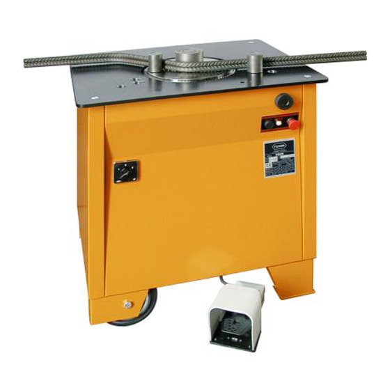
Combined machines
PGT 32/25 three-phase
PGT 32/25 mono-phase
Speed variator
9x9 Panel
www.tecmor.it
E-MAIL: info@tecmor.it
MACHINES TYPE:
Fax. 0365/373030
Bending machines
PG 26 three-phase
PG 26 mono-phase 2 speed
PG 30 three-phase
PG 30 mono-phase
PG 35 three-phase
PG 40 three-phase
Advertisement
Table of Contents

Summary of Contents for TECMOR PGT 32/25 three-phase
- Page 1 Fax. 0365/373030 www.tecmor.it E-MAIL: info@tecmor.it OPERATING INSTRUCTION AND MAINTENANCE MACHINES TYPE: Combined machines Bending machines PGT 32/25 three-phase PG 26 three-phase PGT 32/25 mono-phase PG 26 mono-phase 2 speed PG 30 three-phase PG 30 mono-phase PG 35 three-phase PG 40 three-phase...
-
Page 3: Table Of Contents
CONTENTS: Chapters Page CERTIFICATE OF CONFORMITY ......2 General features of the machine ..... . 3 Transport and unpacking . -
Page 4: Certificate Of Conformity
0365.31.428 fax 0365.37.30.30 CERTIFICATE OF CONFORMITY Company TECMOR srl, declares on its own responsibility that the following product: MACHINE TYPE : . PG.40.... -
Page 5: General Features Of The Machine
PG 30 Mono-phase 86x76xh88 PG 35 Three-phase 86x76xh88 PG 40 Three-phase 1,83 100x85xh88 PGT 32/25 Three-phase 80x88xh86 PGT 32/25 Mono-phase 80x88xh86 Marking: The Certificate of Conformity on page 2 shows the following information: • Name and address of the producer. -
Page 6: Installation And Connection
Installation and connection Prepare the placing space for the machine, which must be perfectly horizontal and strong enough according to the machine weight. The area for the placing of the machine must be completely empty of other material and big enough to grant the worker moving during the use and the maintenance. -
Page 7: Worker Assigned
6 Worker assigned The machine can be used only by experienced staff working directly in the construction or rod-setting sites. The staff can be helped by assistants who must have a safe distance according to the maximum bending length. 7 Worker position The correct worker position must be as indicated in the following picture. - Page 8 8a.2 Starting and working: All the following operations must be executed maintaining the working plate free from any equipment and without inserting any pin into the disc. • Connect the supply cable as above described. • Turn the main switch-inverter from the starting position 0 into position 1 or 2 according to the required rotation direction.
- Page 9 • Place the inversion pin into the disc holes to set the bending angle. Considering position 0 as the limit-switch position, the pin must be placed approximately according to the disc rotation direction. • The exact angle can be found after some bending tests, using the regulation handle for some little angle corrections.
- Page 10 Panel controls: 10. Bending indicator (maximum 9). 11. Pin n° indicator (maximum 9). 12. Pin buttons. 13. Return button. 14. Starting button (including the light). 15. Emergency-stop button. 16. Reset button. 17. Program-light on. 18. Button for programme activation-deactivation. 19. Bending buttons. 8b.2 Starting and working: All the following operations must be executed maintaining the working plate free from any equipment and without inserting any pin into the disc.
-
Page 11: Limitations On The Use
Place and number the pins as follows: The pins are 4, corresponding to the 4 different angles (make some tests to find out the correct position). Place as in the picture, considering that the rotation direction is clockwise: The pin at 60° is n° 1 (the numbering starts with the one nearest the limit switch). The pin at 90°... - Page 12 650 N/mm² 850 N/mm² Type PG 35 three-phase PG 40 three-phase n°bars Ø mandrel 650 N/mm² 850 N/mm² PGT 32/25 three-phase PGT 32/25 three-phase Type Bending Cutting n°bars Ø mandrel 650 N/mm² 850 N/mm² Maximum working performance for mono-phase machines: The supply value (VOLT) must be checked during the working process.
-
Page 13: Malfunctioning, Failure And Breakdown
Malfunctioning, failure and breakdown Following, the most common malfunctioning situations on the machines: a) The machine cannot bend the maximum diameters as in the schedules: • Check if the line voltage is over the tolerance 5%. • Check if the diameter of the cable used to supply the machine is long enough to avoid any current leakage. -
Page 14: Cleaning
Cleaning In case of cleaning do not use any solvents which could damage the machine. Clean and lubricate carefully all the holes and the sliding parts. Machine keeping • In case the machine does not work for a long time, it is better to grease or lubricate the unpainted parts of the machine. -
Page 15: One-Man Safety Devices
This guarantee does not cover the parts subject to a particular wear or wrongly used, not maintained, overloaded or modified The after-sales service during the period of guarantee will be carried out promptly; however TECMOR company will not answer for any possible delay.
Need help?
Do you have a question about the PGT 32/25 three-phase and is the answer not in the manual?
Questions and answers