Advertisement
Quick Links
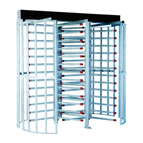
DS400 Series Tandem Full Height Turnstile
Note: Successful turnstile installation depends on reading this manual.
Please keep this service manual after installation. If an installation is done by a construction company
or outside installer, please pass this book along to the end user. This book is required for maintenance,
troubleshooting & repairs.
512-321-4426
INS-DS400T-190401
Service & Installation Manual
Designed Security, Inc - 1402 Hawthorne Street, Bastrop Texas 78602 - (800) 272-3555
sales@dsigo.com
1
Advertisement

Subscribe to Our Youtube Channel
Related Manuals for DSI DS400 Series

Summary of Contents for DSI DS400 Series
- Page 1 DS400 Series Tandem Full Height Turnstile Service & Installation Manual Note: Successful turnstile installation depends on reading this manual. Please keep this service manual after installation. If an installation is done by a construction company or outside installer, please pass this book along to the end user. This book is required for maintenance, troubleshooting &...
- Page 2 Important Electrical Information Installation of the control head mechanism into the turnstile requires a grounding-type outlet recep- tacle installed inside of the frame or cabinet through the provided conduit access points. To reduce the risk of electric shock, this equipment has a grounding type plug that has a third Additionally, the P24-60W power supply from this appliance must be grounded to the frame of the turnstile.
- Page 3 Table of Contents Important Electrical Information DS400 Series Tandem Full Height Data Sheet DS400 Series Tandem Full Height Components DS400 Series Tandem Full Height Fastener List Pre-Installation Tips Wedge Type Concrete Anchor Instructions Installation Instructions 6500 Series Control Head Mechanical Overview...
- Page 4 The High-Security Series DS427-T | DS430-T Full-Height Turnstile (Tandem) | Interior & Exterior Application Size Options: (pedestrian clearance) The High-Security Series units can be DS427-T: 27” (685.8mm) engineered to meet all your security and DS430-T: 30” (762mm) 304 Stainless, No. 4 Satin control requirements, and can be created as nish (shown) stand-alone units, or as part of an integrated...
- Page 5 The High-Security Series DS427-T | DS430-T Full-Height Turnstile (Tandem) | Interior & Exterior Application Applications: Available Finishes: • Hot dipped galvanized carbon steel both indoor and outdoor settings • Carbon steel with powder coating (standard color is black/ other colors available upon request) •...
- Page 6 DS400 Series Tandem Full Height Components Each DS400 Series tandem full height turnstile comes with the following components: 1x Main Channel 1x A Rotor 1x B Rotor 1x AABB Barrier 1x ABBC Barrier Lowest arm recessed several Standing upright and facing...
- Page 7 High Security Series Tandem Full Height Turnstile Fasteners All High Security Series Full Height Tandem Turnstiles For mounting the cross arms to the main channel For mounting the control head to the mainframe For mounting the four yoke assemblies to the cross arms For mounting the barriers to the cross arms Qty 14 - 3/8“-16 x 3.75”...
- Page 8 Tandem Full Height Pre-Installation Electrical Tips If the unit is to be electronically controlled, pre-plan how it will be wired. We provide several options for running conduit to each turnstile. Each end of the main channel is designed to accept up to two 3/4” conduits, and also allow for multiple units to be bolted together. The stationary barriers (which run vertically from the concrete to the mainframe) connects to the 2”...
- Page 9 Wedge Type Concrete Anchor Instructions Select a carbide drill bit with a diameter equal to the anchor diameter. Drill hole at least 1/4” deeper than nominal anchor embedment. Clean hole with pressurized air or vacuum to remove any excess dust/debris. Using the washer and nut provided, assemble the anchor, leaving nut one half turn from the end of anchor to protect threads.
- Page 10 Installation Instructions 1.) If needed, pour a level concrete pad at least 4” thick and 4” greater than the unit’s 2.) Unpack turnstile(s) and verify all parts are included. Use the parts checklist in the beginning of this book. 3.) Unwrap the main channel from the cardboard & foam packaging. Remove the 9x canopy diagram provided with option for proper assembly technique in that instance.
- Page 11 Installation Instructions (continued) 5.) Assemble cross arms to mainframe using the provided 3/8” x 3” carriage bolts as illustrated below. Ensure cross arms are square to mainframe and that the cross arms heads and may need to be hammered into the round holes of the cross arms. Side hole on Side hole on Side hole on...
- Page 12 Installation Instructions (continued) 7.) Following the concrete anchor installation directions, drill each of the marked holes marked for the 3/8” anchors. Be sure to remove debris from holes before installing the anchors. 8.) Install the curved yoke assemblies onto the concrete over the anchors. Take special notice of the two screws and extra hole on one side of the yoke strap.
- Page 13 Installation Instructions (continued) 9.) Install vertical barrier assemblies over the anchors onto the concrete as shown below. The concept is that the left side of the tandem will have one set of arms from each barrier that are raised while the right side will have arms that are lower. ABBC Barrier AABB Barrier AABB Barrier...
- Page 14 Installation Instructions (continued) 11.) Place assembled mainframe on top of yokes and stationary barriers. Attach barriers and yokes to cross arms by using the provided 14x 2” carriage bolts and serrated ange nuts. A 9/16“ deep wall socket will be required for this step. Unless ordered with optional canopy or yoke guards, insert black plastic plugs into the 1.125”...
- Page 15 Installation Instructions (continued) 12.) If necessary, level the mainframe by shimming from under the yokes and the barrier. Once level, secure these components to the concrete by adding the nuts to the anchors. dropping it from the mainframe’s output holes. Mark the concrete for drilling in these positions.
- Page 16 Installation Instructions (continued) 15.) Place rotor assemblies on the roller bearing assemblies. Rotor A will have the properly, the arms should mesh through the arms on the stationary barriers. ABBC Barrier A Rotor B Rotor A Rotor B Rotor AABB Barrier 16.) Utilizing the diagram below, align the rotors to the correct position.
- Page 17 Installation Instructions (continued) 17.) Mount the two control heads to the mainframe using the provided 3/8-16 carriage bolts. Unless equipped with key overrides, it does not matter if the springs are pointed to the left or the right. Be aware that the control heads 18.) If required, refer to the wiring diagram &...
- Page 18 6500 Series Control Head Mechanical Information All of our turnstiles and ADA gates operate with a mechanism called the 6500 Series Control Head. This sturdy and easy to maintain drive for the turnstile has replaced all previous model control heads. It is adaptable to nearly any existing turnstile and comes with each new turnstile purchase.
- Page 19 Designed Security, Inc - 1402 Hawthorne Street, Bastrop Texas 78602 - (800) 272-3555 512-321-4426 sales@dsigo.com INS-DS400T-190401...
- Page 20 Complete control heads are available upon request. Contact us for pricing details. Control Head Castings Locking Bar Assemblies – I2 IB IC ID IE 0373 - Bottom Casting 0382 - Fail Open Assembly XD10 0740 - Logic Controller (XD10) – 0372 - Top Casting 0383 - Fail Lock Assembly Shock Housing Assemblies...
- Page 21 operating with the 6500 Series Control Head self-center with a spring driven indexing pin and hydraulically shock to the home position to prevent damage or injury. Manual both ways: with an out of service lockout bar which would allow the end user to lock the turnstile with a standard pad lock.
- Page 22 6500 Series Control Head Locking Bar Information The 6500 Series Control Head is built to order based on a direction set up sheet sent with cabinet on the left for waist high. “No passage” directions include a fail lock locking bar assembly as well as an unwired solenoid. This adds the appropriate parts to the control head to prevent it from rotating in that direction.
- Page 23 6500 Series Control Head Locking Bar Information (Continued) Extra components are required to do so. Locking bar assemblies are held together with 1/8” spring pins. Extracting these pins and Replacing an entire locking bar assembly is simple; punch the .5” dowel pin from the pivot point through the head casting (via a small hole in the bottom casting for this purpose), pull out the old locking bar assembly and replace it with the new one.
- Page 24 6500 Series Control Head Hydraulic Shock Information The 6500 Series Control Head utilizes a spring loaded index pin for auto-centering the cam Set properly, the shock will allow a turnstile or gate to self-center while rotating smoothly without slamming. use a .75” diameter shock while larger full heights use a 1” diameter shock. Index Pin Hydraulic Shock 3/4”...
- Page 25 6500 Series Control Head Electrical Information Each electronic control head comes with a power supply, a programmable logic controller (PLC), limit switches (or optionally, proximity sensors) and solenoids. For safety purposes, it is recommended that you read all literature on the electrical components before attempting to install the control head into a turnstile.
- Page 26 6500 Series Control Head w/ XD10 Controller Standard Wiring Diagram Input Voltage: Direction 1 Direction 2 Direction 1 Direction 2 100-240 VAC Access Control Relay Access Control Relay Override Relay Override Relay 1 Phase N.O. N.O. N.O. N.O. 1.1 - .6A Max 50/60 Hz + –...
- Page 27 6500 Series Control Head w/ XD10 Controller Standard Wiring Legend – I2 IB IC ID IE Direction 1 - Clockwise on full height turnstiles or cabinet on right for waist high turnstiles & ADA gates. Inputs Dir 1 Dir 2 Dir 1 Dir 2 Dir 1...
- Page 28 6500 Series Control Head Limit Switch Information Electronically controlled 6500 Series Control Heads utilize limit switches (or optionally, proximity sensors) in order to detect rotation. Depending on the type of unit (turnstile or ADA gate), the limit switch for a direction may be on the left or the right hand side of the control head. Turnstile Control Head ADA Gate Control Head Limit...
- Page 29 6500 Series Control Head w/ XD10 Controller Standard Turnstile Settings The XD10 logic controller on the 6500 Series Control Head has a text based menu screen to adjust settings and view statistics of the turnstile. Pressing the A button will cycle to each of the screens available on the device.
- Page 30 6500 Series Control Head w/ XD10 Controller Standard Turnstile Testing The XD10 logic controller on the 6500 Series Control Head can be activated by contact closures between 24VDC+ and the relevant input. New technology allows for simpler on-board testing as well. To diagnose issues with the unit, press A on the keypad to cycle between screens until the testing mode screen appears.
- Page 31 Maintenance & Cleaning tained more frequently. Annual Servicing - Secure all nuts & bolts throughout each model. This includes concrete anchors, carriage bolts holding together mainframes, and the bolts holding the control head assembly together. - Remove the index pin assembly from the control head by disconnecting the two extension springs &...
- Page 32 6500 Series Control Head w/ XD10 Controller Troubleshooting Symptoms Causes Solutions Verify outlet receptacle installed Power supply is not receiving in mainframe / cabinet is input voltage. operating correctly and that the power supply is plugged in. Remove + lead from power supply output.
- Page 33 6500 Series Control Head w/ XD10 Controller Troubleshooting Symptoms Causes Solutions Access control device output Wire access control to I1 or I2 connected to override inputs. with one-shot timer enabled. This can be avoided by enabling the one-shot timers built into the Access control device output set logic controller program.
- Page 34 6500 Series Control Head w/ XD10 Controller Troubleshooting Symptoms Causes Solutions Remove locking bar assembly from control head (easiest way on Mechanical bind between locking Unit remains locked after access non-key lock models is to punch bar and cam assembly (typically control is presented until arm is out dowel pin pivot point from from unit being out of plumb or...
- Page 35 Proper Turnstile Usage The 6500 Series Control head is easy to use. There are a few things that users should be trained on and informed of. - In the case of an electronic turnstile, approach the unit and present access control credentials. Do not push on the arms of the rotor until after the access control device successfully unlocks the turnstile.
- Page 36 Warranty Information The DSI Product you have purchased is warranted to be free of defects in material and workmanship when properly installed, used, and maintained according to instructions. DSI will, for a period of one (1) year, three (3) years for Optical Turnstiles, from date of purchase repair or replace any part which, upon our examination, prove to be defective under normal use.
Need help?
Do you have a question about the DS400 Series and is the answer not in the manual?
Questions and answers