Advertisement
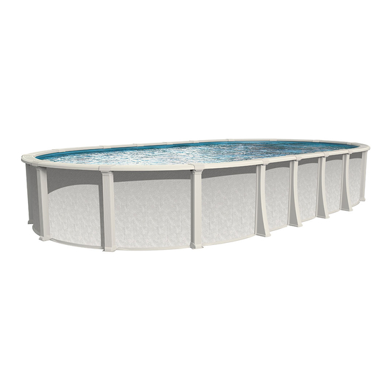
SENTINELLE
POOL
Specific instruction sheet
Note : This instruction sheet manual includes installation instructions for
specific items related to the SENTINELLE OVAL pool. All the other steps must
be followed in the main instruction manual.
1- SUPPORT POSTS INSTALLATION
Insert the post base on the junction plate. Be sure that the plate hooks
are inserted in the post base openings. (figure 1.1)
Insert a 1 inch screw (Q) on each side of the post base
in the screw holes. (figure 1.2)
Insert the two tabs of the securing hook in the
openings on top of the post. The part must not be too
tight initially because it will need to be pulled out
when installing the liner. (figure 1.3)
When the liner is installed, re-install the
securing hook. A mallet could be necessary to insert it
tightly. After this step, the post should be lined up
against the wall. (figure 1.4)
Figure 1.1
OVAL CONTOUR SYSTEM
Figure 1.2
Figure 1.3
Figure 1.4
1
Advertisement
Table of Contents

Summary of Contents for Oasis Aqua Leader Sentinelle
- Page 1 SENTINELLE POOL OVAL CONTOUR SYSTEM Specific instruction sheet Note : This instruction sheet manual includes installation instructions for specific items related to the SENTINELLE OVAL pool. All the other steps must be followed in the main instruction manual. 1- SUPPORT POSTS INSTALLATION Insert the post base on the junction plate.
- Page 2 2- TOP RAILS INSTALLATION Position and place the top rails as indicated in figure 2.1. The top rail must be pushed at the maximum to the inside of the pool to ease the future seat caps installation. Insert the 1 inch screws (Q) and screw gently. Even the space of each top seat ends to make sure it is centered between the uprights.
- Page 3 Seat cap Insert the front part of the seat cap (outside of the pool) in the collar opening. Push down to the back (inside of the pool) and snap on the top rail by taking care of inserting the seat cap central rib in the post head slot. (figure 3.3 and 3.4) Figure 3.3 Figure 3.4...
- Page 4 Description Piece number 15x26 15x30 18x33 18x40 21x43 J- Support post Support post 102_ _ 0100_ _ K- Top seat Curved top seat 57” 101_ _010000 L- Seat cap Seat cap 10300_ _E00 M- Collar Collar 11900_ _E00 N- Securing hook Securing hook 11800_ _E00 O- Base cover...
- Page 5 Description Piece number 15x26 15x30 18x33 18x40 21x43 AA- Gussets Right gusset 2GUR000 Left gusset 2GUL000 BB- Top plate Metal top plate 2MTP000 CC- Top plate Resin top plate 1040033E01 DD- Bottom plate Resin bottom plate straight section 104_ _000000 EE- Bolt 5”...
- Page 6 Exploded view Round section...
- Page 7 Straight side section...
- Page 8 Real sizes AQUA LEADER reserves the right to modify or alter any construction specifications without notice. Manufactured by AQUA LEADER, 2370 de la Province Longueuil, QC, J4G 1G1 REVISION 01/07...
Need help?
Do you have a question about the Aqua Leader Sentinelle and is the answer not in the manual?
Questions and answers