
Summary of Contents for DURAG D-ISC 100 2 Series
- Page 1 D-ISC 100 x xx2 Universal control unit Before starting any work please read the operating manual! Article no.: GmbH • Kollaustraße 105 • 22453 Hamburg • Germany • www.durag.com 4 019 392...
- Page 2 Must not be reproduced or transferred in any manner, language or medium, electronic or mechan- ● ical, without the express permission of DURAG GmbH. The same applies to parts of the manual. © DURAG GmbH 2017 All rights reserved.
-
Page 3: Table Of Contents
Individual sensor connection..................... 45 4.2.8 Dual sensor connection .................... 46 4.2.9 Basic Modbus information.................... 47 4.2.10 Information on the DURAG Modbus protocol .............. 47 Top hat rail expansion module.................. 48 4.3.1 Assembly of top hat rail expansion modules.............. 48 4.3.2 Disassembling top hat rail modules .................. 51 4.3.3... - Page 4 Contents 4.3.7.2 Connections and termination .................... 59 4.3.7.3 LEDs .......................... 60 4.3.7.3.1 Meaning of system LED 1.................... 61 4.3.7.3.2 Meaning of system LED 2.................... 61 4.3.7.3.3 Meaning of the field bus LED.................... 62 4.3.7.3.4 Meaning of the internal communications LED .............. 62 Storage, dismantling and disposal .................. 63 4.4.1 Dismantling ........................ 63 4.4.2...
- Page 5 Contents DURAG Modbus ....................... 91 [Backup/Restore] ...................... 92 9.4.1 [Backup system settings] .................... 92 9.4.2 [Restore system settings].................... 93 9.4.3 [Restore factory settings] .................... 93 [Device description update].................... 94 [Firmware update] ...................... 94 Channel setup menu 4 96 10.1 [Status and Messages] [] .................... 96 10.1.1 [Device status ]D-ISC 100 (D)................... 98 10.1.2...
- Page 6 Examples of settings 156 15.1 Example: Display setup .................... 156 15.2 Example: Setting/checking the time................ 157 15.3 Example: Setting / checking DURAG the Modbus............ 158 15.4 Example: Clearing the PIN protection (logging in) ............ 159 15.5 Example: Change PIN code.................... 162 15.6 Example: Deactivate PIN lock.................. 164 15.7...
- Page 7 Contents 15.8 Examples: Parameterising sensors ................ 167 15.8.1 Sensor: Common parameter................... 168 15.8.2 Sensor: Specific parameter..................... 169 15.9 Examples: Selection of the displayed data .............. 170 15.9.1 Example: Selection of the displayed measurement channel .......... 170 15.9.2 Example: Selection Number of the displayed measurement channels...... 171 15.10 Examples: Assignment of the analogue output (current output) ........ 173 15.10.1...
- Page 8 Contents D-ISC 100 x xx2...
-
Page 9: Information On This Manual
Universal control unit (depending on the connected devices) are described in the relevant operation manuals for these components, e.g.: DURAG bus systems D‑ESI 100 DURAG Engineering and Service Interface D-TB xxx Terminal box D-BL xxx blower unit DURAG measuring devices... - Page 10 1 | Information on this manual Risk of injury due to wrong spare parts! WARNING Incorrect or defective spare parts can result in damage or malfunctions and may also impair safety. ▶ Only use original spare parts of the manufacturer. ▶...
-
Page 11: Safety
2 | Safety Safety General safety information Installation, commissioning, operation, maintenance and dis- mantling must only be carried out by qualified specialised per- sonnel and electrical work only by qualified electricians (see Personnel, qualifications [} 11]). The personnel qualification required for a particular activity is specified in the corresponding chapters. -
Page 12: Fundamental Hazards
2 | Safety Fundamental hazards Follow the safety instructions listed here and the warning inform- ation in the subsequent chapters of this manual in order to re- duce health hazards and prevent dangerous situations. 2.3.1 Hazards due to electric current Before commissioning the device, it must be ensured that... -
Page 13: Designated Use
2 | Safety Designated use The Universal control unit D‑ISC 100 parameterises, monitors and controls DURAG sensors. The D‑ISC 100 - Universal control unit is not suitable … for use in atmospheres saturated with water vapour ● for use in potentially explosive atmospheres ●... -
Page 14: Device And Function Description
Purge air supply for one sensor (D-ISC 100 P only) ● Up to eight DURAG sensors can be connected to a D-ISC 100 operation unit. The operation unit has a modular structure and can be expanded to include expansion modules. -
Page 15: System Overview
Status: S1.3:Normal measurement Table 3.1: System examples Line types Connecting cable for supply voltage DURAG Modbus (process) ≤ 1000 m or analogue/digital interface Device connection cable (with plug) ≤ 20 m DURAG Modbus (field) ≤ 1000 m Purge air tube Monitoring room • Central device monitoring and measuring value displays... -
Page 16: Variants, Design Types
3 | Device and Function description Name • Function Welded-in pipe with flange and seal • Process connection D-R 808 measuring device • Monitoring of dust concentration D-R 320 measuring device • Monitoring of dust concentration D-FL 220 measuring device • Monitoring of speed and volume flow of gases D-ISC 100 P universal operation unit D-ISC 100 C universal operation unit 01.04.2013 12:34 S1:D-R 320... -
Page 17: Designation Of Device Components
3 | Device and Function description Design Description without purge air blower: D−ISC 100 C Operation unit in compact field housing ● option of extending with extra software modules ● D−ISC 100 M Operation unit in field housing ● Option of extending with extra software modules ●... - Page 18 3 | Device and Function description Display (example) D-ISC 100 C, M, P, R 01.04.2013 12:34 S1:D-R 220 S1.1:D-R 220 - Opacity 61.8 % OP 35.0 70.0 Status: S1.3:Normal measurement 11 Header 12 Display area 13 Status bar Table 3.5: The display Keyboard D-ISC 100 C, M, P, R 25 26 27...
-
Page 19: Cpu Module
3 | Device and Function description LEDs D-ISC 100 C, M, P, R 31 32 33 34 35 Ready for operation Warning/mainten- Fault ance Bus data error Bus active Table 3.7: LEDs 3.3.2 CPU module CPU module D-ISC 100 C, M, P, R 54 55 56 57 83 81 31 LED status ready for operation... -
Page 20: D-Isc 100 M
81 Ethernet (for internal Modbus TCP module) 83 Display unit connection 84 USB port (2x) X2 DURAG Modbus connection X3 Analogue/digital out connection X4 Connection between two meas- X5 Connection of operating voltage uring heads (pre-wired) 24 V (pre-wired) X6 Connection of sensor Modbus (pre-wired) Table 3.8: CPU module... -
Page 21: D-Isc 100 P
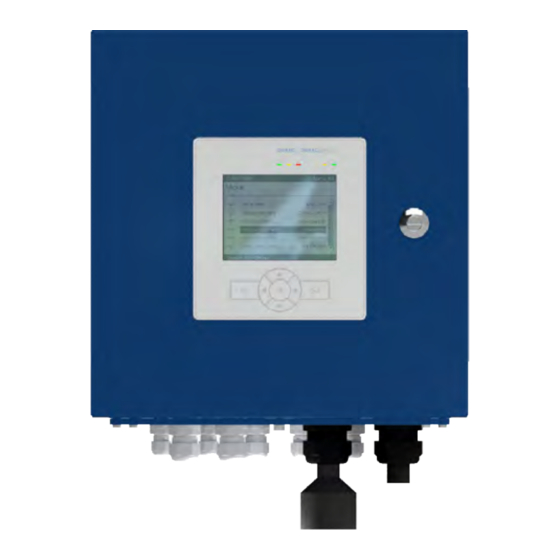
3 | Device and Function description 3.3.4 D-ISC 100 P D-ISC 100 P 10 Display 20 Keyboard 30 LEDs 42 Lower housing part 43 Housing door 45 Lock 46 Device fastening 48 Rails for 61 Power supply unit shield terminals 62 Top hat rail module 63 Expansion module 72 Cable glands... -
Page 22: D-Isc 100 C
3 | Device and Function description 76 Vent plugs 83 Display unit connection 91 Fresh air purge air feed 92 Purge air connection 93 Fan 94 Purge air filter X1 Plug terminals for device connection (see Technical data for operating voltage) Table 3.10: Parts designation D-ISC 100 P 3.3.5 D-ISC 100 C... -
Page 23: D-Isc 100 R
3 | Device and Function description 3.3.6 D-ISC 100 R D-ISC 100 R 10 The display 20 Keyboard 30 LEDs 46 Device fastening 47 Top hat rail 48 Rails for shield terminals 49 Shield terminals 61 Power supply unit 62 Top hat rail module D‑ISC 100 CPU module (3.3.2 CPU module [} 19]) -
Page 24: Expansion Modules
3 | Device and Function description 3.3.7 Expansion modules Designation of components on the top hat rail 31 D‑ISC 100 CPU module 32 Top hat rail module 33 Terminal end holder 34 Top hat rail 35 Bus connector Table 3.13: Components on the top hat rail Designation of the top hat rail module components ( in this case digital output module) D-ISC 100 x xx2... -
Page 25: Expansion Modules
3 | Device and Function description Top hat rail module 41a LED (orange): there is current at the re- 42 Module 45 Changeover switch for lay coil connecting terminals relay NO / NC 41b Ready-for-operation LED (green); 43 Hinged cover 46 Terminal assignment of flashes module connecting termin- during internal communication... - Page 26 3 | Device and Function description 4 x analogue output 0-20 mA/400 Ohm ● Zero point (live zero) 4 mA ● The analogue output expansion module allows the determined measured values from the D‑ISC 100 to be issued as current sig- nals. Analogue input (AI) Top hat rail expansion module see also 4.3.3 Analogue input [} 52]...
- Page 27 3 | Device and Function description 8 x digital input ● Configurable function ● The digital input expansion module allows actions or functions ● (e.g. maintenance mode, zero point measurement) to be triggered by the D‑ISC 100 via an external status signal (0/1). Software expansion modules Software modules are available either included with the D‑ISC 100 or as optional extras.
- Page 28 (temperature and absolute pressure) to be recorded and dis- played for the entire measurement system and to be forwarded to all connected DURAG sensors in order to standardise the measured values . The following sources can be used as measured values for these...
-
Page 29: Installation And Commissioning
4 | Installation and commissioning Installation and commissioning Installation Suitable lifting devices should be used to load and unload the Transport packages if necessary. to the installation location Avoid rough impacts. If possible, use the original packaging for transport. If there are large temperature or humidity fluctuations, condensa- tion can cause moisture to form within the devices. - Page 30 4 | Installation and commissioning The clips should not project laterally beyond the outline of the casing. Therefore, for the fastenings use the hole in the clip next to the outer edge. The figure below shows attachment to the long edge (A) and the short edge (B). Maximum torque when tightening the screws: 10 Nm.
-
Page 31: D-Isc 100 C
4 | Installation and commissioning Do not use hoses as attachments or supports for other ob- ● jects. The purge air hose for the sensor is attached to the hose con- ● nection on the D‑ISC 100 P using a hose clamp. 4.1.2 D-ISC 100 C Standard installation... -
Page 32: Connecting The Network And Data Cables
4 | Installation and commissioning A description of the connections can be found in Section Connecting the network and data cables [} 32]. Connecting the network and data cables Danger of death due to electric current! DANGER An immediate danger of death exists in case of contact with live parts. -
Page 33: Notes On Connecting Data Cables
Enabling/Disabling the bus termination Bus termination ● Terminating DURAG Modbus at both ends. To do so, activate ● the termination at the devices at the ends of the bus To carry out the bus termination, see also the information in the operation manuals for the connected sensors. - Page 34 4 | Installation and commissioning Data cable connection 03 04 01 Loosen/tightly screw in the 02 Moving the terminal knurled screw 03 Shield terminals 04 Terminal holder Fig. 4.1: Shield terminals Strip back approx. 20 mm of the outer insulating layer of the data cable above the screen in addition to the free cores.
-
Page 35: Electrical Connection
4 | Installation and commissioning 4.2.3 Electrical connection Danger of death due to electric current! DANGER An immediate danger of death exists in case of contact with live parts. Damage to the insulation or individual components can present a danger of death. ▶... -
Page 36: Bus Connection
D‑ISC 100 CPU module or using M12 connectors. Additional in- (conventional) formation on this is provided in this section. The wiring of the individual components in a DURAG sensor sys- tem is described in the following sections. D-ISC 100 x xx2... - Page 37 Connector descriptions can be found in the following table. Connector Description Comments Sensor – Modbus Connection of a sensor or an up- (Modbus – master) stream D‑ISC 100*. Durag – Modbus Only available with Modbus RTU – (Modbus – slave) slave expansion module. Connec- tion of an evaluation system or a downstream D‑ISC 100*. Ethernet...
- Page 38 The following expansion modules are delivered with the listed in- stallation connectors as standard. If the expansion modules are ordered together with a D‑ISC 100, they will already have been installed at the factory. Expansion module Modbus RTU (X2, DURAG Modbus) Quantity Name Type Pos* M12 A-coded...
- Page 39 4 | Installation and commissioning Expansion module Profibus DP Quantity Name Type Pos* M12 B-coded male M12 B-coded female The "sensor" X6 connection is usually connected to the factory- installed sensor connection cable. With the D‑ISC 100 M and D‑ISC 100 P, the connection can also be guided out of the hous- ing with an M12 connector **(must be ordered separately): X6: Sensor (Modbus Master) Quantity Name...
- Page 40 4 | Installation and commissioning 2 (3) Fig. 4.7: Position of the connector with D‑ISC 100 C D-ISC 100 x xx2...
-
Page 41: Sensor Network Bus Architecture (One D-Isc 100)
4 | Installation and commissioning 4.2.5 Sensor network bus architecture (one D-ISC 100) Modbus Modbus Slave Slave Adr. y Adr. z Modbus Master Modbus Slave Adr. x Modbus Master rogrammable ogic ontroller D-EMS 2000 Environmental- and Process Data Management System D-ESI 100 URAG ngineering and ervice nterface... - Page 42 4 | Installation and commissioning The connecting cables to the sensors (Sa and Sb) are pre-wired at the terminals of the D‑ISC 100 and the D−TB 100. There are connectors on the other ends of the cables. The sensors are connected exclusively via this connector. The operator does not need to carry out any local wiring work on the terminals! Communication between the D‑ISC 100 and the sensors is per- formed via a serial Modbus connection.
-
Page 43: Sensor Network Bus Architecture (Multiple D-Isc 100)
4 | Installation and commissioning 4.2.6 Sensor network bus architecture (multiple D-ISC 100) Modbus Modbus Slave Slave Adr. y Adr. z Modbus Modbus Master Master Modbus Modbus Slave Slave Adr. w Adr. x Modbus Master Modbus Slave Adr. v Modbus Master rogrammable ogic ontroller D-EMS 2000... - Page 44 D‑ISC 100 menu path: Standard display (e.g.: S1.1) User mode (menu 1) System setup (menu 3) Date/Time DURAG Modbus Communication Settings Network mode A D‑ISC 100 can supply a sensor with the necessary operating Power supply voltage. The D‑ISC 100 P also supplies the necessary purge air.
-
Page 45: Individual Sensor Connection
4 | Installation and commissioning In principle, a D‑ISC 100 can only operate/parameterise those sensors that are connected via the Modbus Master interface of a D‑ISC 100. The following therefore applies: D‑ISC 100 Operates/parameterises sensor (Db) (Sa) (Dc) (Sb) (Da) (Sa) and (Sb) All buses must be terminated at each end. -
Page 46: Dual Sensor Connection
4 | Installation and commissioning If the sensor has not yet been operated with the D‑ISC 100, it will firstly need to be assigned. ✔ Following successful assignment, the new sensor can be op- erated using the D‑ISC 100. 4.2.8 Dual sensor connection With dual sensors (e.g. -
Page 47: Basic Modbus Information
The data are transmitted in binary form. This form of the Mod- ● bus is designated as RTU. The DURAG Modbus is based on the Modbus protocol, and ● also defines additional information such as register assign- ments. -
Page 48: Top Hat Rail Expansion Module
4 | Installation and commissioning Top hat rail expansion module Danger of death due to electric current! DANGER An immediate danger of death exists in case of contact with live parts. Damage to the insulation or individual components can present a danger of death. ▶... - Page 49 4 | Installation and commissioning Replacing an existing module An existing module is to be replaced with another module of the same type. (with the same module type) The old module is not removed from the D‑ISC 100 configura- tion using the D‑ISC 100 user interface. Disconnect the D‑ISC 100 from the power.
- Page 50 4 | Installation and commissioning Now carefully push the top hat rail module onto the top hat rail (figure on the left - 1). Lock the top hat rail module onto the rail by pushing both tabs (figure on the left - 2) towards the top hat rail. ✓...
-
Page 51: Disassembling Top Hat Rail Modules
4 | Installation and commissioning 4.3.2 Disassembling top hat rail modules Proceed as follows to disassemble a top hat rail module: (You can find the parts designation on page [} 24]) Before disassembly, a top hat rail module that is no longer needed is firstly removed from the system using the D‑ISC 100 user interface (see Section 10.4.2 Mx: Remove... -
Page 52: Analogue Input
4 | Installation and commissioning 4.3.3 Analogue input Description Module connecting terminals Module connecting terminals Service LED 9 green LED ON when in operation; FLASHING during communication (internal) LED 10 LED ON in event of expansion module fault LED 11 blue LED ON when USB connected LED 9 LED 10 LED 11... -
Page 53: Analogue Output
4 | Installation and commissioning Monitor Measured value converter Voltage source with current output Digital multimeter/monitor Current measurement Table 4.6: Connection of analogue input module Type Description Equivalent circuit for the analogue input expansion module 2-wire transmitter 3-wire transmitter Transmitter with its own power supply External digital multimeter for test purposes Table 4.7: Plug assignment for the analogue input expansion module, example AIx.1... - Page 54 4 | Installation and commissioning Plug posi- Description Plug posi- Description tion tion X1.1 AO x.1 AO+ evaluation system + X2.1 AO x.3 AO+ evaluation system + X1.2 AO−evaluation system- X2.2 AO−evaluation system- X1.3 MO+ measuring instrument X2.3 MO+ measuring instrument (monitor pick-up) (monitor pick-up) X1.4...
-
Page 55: Digital Input
4 | Installation and commissioning 4.3.5 Digital input Description Module connecting terminals 5 6 7 8 Module connecting terminals Service LED 1−4 orange LED ON when IN and GND are conductively connected LED 5-8 orange LED ON when IN and GND are conductively connected LED 9 green... -
Page 56: Digital Output
4 | Installation and commissioning 4.3.6 Digital output Description Module connecting terminals 5 6 7 8 Module connecting terminals SW2.8 Service SW2.7 SW2.6 SW2.5 LED 1−4 orange LED ON when there is voltage at the relay coil . LED 5-8 orange LED ON when there is voltage at the relay coil . -
Page 57: Expansion Module Profibus Dp
4 | Installation and commissioning 4.3.7 Expansion module Profibus DP Installing and connecting the module in the D‑ISC 100 housing. The Profibus DP expansion module is factory-installed on the right next to the main board as an external converter. The Mod- bus RTU Slave software module is needed to connect the Profibus DP module. - Page 58 Table 4.16: Modbus RTU module factory setting communication parameters Additional user information is available for the Profibus DP module. This publication provides the register maps and definitions of the register contents. Contact your DURAG representative (see [} 211]) if necessary. D-ISC 100 x xx2...
-
Page 59: Address Setting
4 | Installation and commissioning 4.3.7.1 Address setting Rotary switch Rotary switch for Profibus Slave address for Profibus Slave address (10) The Profibus slave address is set between 1 and 99 using the rotary switch (see figure on the left, position 6 and 7). Rotary switch (6) has a value of 10, while rotary switch (7) has a value of 1. -
Page 60: Leds
4 | Installation and commissioning The 9-pole sub-D plug connector for the internal Profibus plug (see figure on the left) can be used for diagnostic purposes. Fig. 4.20: Profibus sub-D-plug connector Connector Cable Colour Comment green... -
Page 61: Meaning Of System Led 1
4 | Installation and commissioning 4.3.7.3.1 Meaning of system LED 1 No./ Status Meaning colour(s) Duo LED yellow/green System LED (SYS) green firmware started yellow Status must only arise briefly If the LED is permanently yellow, this may indicate a hard- ware defect. -
Page 62: Meaning Of The Field Bus Led
4 | Installation and commissioning 4.3.7.3.3 Meaning of the field bus LED No./ Status Meaning colour(s) Duo LED red/green Field bus LED (COM) green RUN, cyclical communication Incorrect Profibus DP configuration flashes STOP, no communication, connection error cyclically flashes not configured acyclically Table 4.21: Flash code meaning of the field bus LED (COM) 4.3.7.3.4... -
Page 63: Storage, Dismantling And Disposal
4 | Installation and commissioning Storage, dismantling and disposal 4.4.1 Dismantling Risk to life due to electric current! DANGER There is an immediate risk to life when touching parts carrying live voltage. ▶ Only have work on electric systems performed by specialised electricians. -
Page 64: Disposal
4 | Installation and commissioning 4.4.3 Disposal After reaching the end of its useful life, the product must be dis- posed of in accordance with regulations. Do not treat the product as normal domestic waste. Observe the relevant local and coun- try-specific regulations. -
Page 65: Basic Operation Of The D-Isc 100
5 | Basic operation of the D-ISC 100 Basic operation of the D-ISC 100 Prerequisite You have selected clear display language: ● Language setting (menu 3.2) − ○ [ System setup > Language] see also Section 9.2 [Language] [} 90]. ○ PIN protection is deactivated (symbol in the status bar) or ●... -
Page 66: D-Isc 100 Display
5 | Basic operation of the D-ISC 100 No. Meaning Applies to (for example) for input: change value (via the cursor) (increase) ● for a menu: call up the next higher menu ● in the menu list: change / scroll through the selection (menu bar) ●... -
Page 67: Presentations In The Display
5 | Basic operation of the D-ISC 100 5.2.1 Presentations in the display Displays show measured values and messages. It is not pos- ● sible to edit these or to adjust any settings here! Fig. 5.1: Display Displays can be identified by the date and time in the header bar (see example on the left). - Page 68 5 | Basic operation of the D-ISC 100 Output of one measured value Output of one measured value with additional bar graph display Output of two measured values (additional bar graph displays can be shown for both values) Output of four measured values (additional bar graph displays can- not be shown for the values) Table 5.2: Value display in the D-ISC 100 display...
- Page 69 5 | Basic operation of the D-ISC 100 Menu: 1 Menu User mode Display setup System setup Channel setup Login / Logout About D-ISC 100 Specific parameter Specific parameter Status: S1.3:Normal measurement Table 5.3: Main menu Note the menu address shown on the right-hand side of the header bar (here menu: 1).
-
Page 70: Virtual On-Screen Keyboard
5 | Basic operation of the D-ISC 100 Meaning of the symbols in the screen menu PARAMETERS Display (read only) DISPLAY Checkbox: status Status inactive PARAMETERS Setting DISPLAY Checkbox: (can be edited) status Status active PARAMETERS Setting DISPLAY Checkbox: (can be edited after entering status Status active with activ- a valid PIN) - Page 71 5 | Basic operation of the D-ISC 100 Fig. 5.4: Menu 5.1.2 with the virtual on-screen keyboard I The arrow keys ( ) on the keypad [} 203] (on the device housing) can be used to select the characters on the on-screen keyboard [} 204] (display).
-
Page 72: Menus, Structure And Navigation
5 | Basic operation of the D-ISC 100 5.2.4 Menus, structure and navigation There are various menus for the configuration of: The display ● D‑ISC 100 ● Connected sensors ● Used modules ● Pressing the key from a measured value display opens up the Menu: 1 main menu. -
Page 73: Measured Value And Status Displays
5 | Basic operation of the D-ISC 100 Pressing the key again generally leads directly back to the measured value display. You will always be taken back to the place at which you previously left the measured value display. Info box message: Changes on system settings saved successfully] If you have moved within the settings menu, even without making any changes, you may still receive an info box message... - Page 74 5 | Basic operation of the D-ISC 100 Component Function Status display Measurement display Software module Media conditions (MC0) Software module Modbus TCP (NE0) Software module Modbus RTU (NS0) Expansion module Analogue output (AOm)* Expansion module Analogue input (AIm)* Expansion module Digital output (DOm)* Expansion module Digital input (DIm)*...
- Page 75 5 | Basic operation of the D-ISC 100 Display of the measured values selected for the respective ● sensor, together with the respective unit. Fig. 5.11: Measurement display MXo Measurement display (Sn) Displays the measured values selected for the respective ex- Measurement display (SXp) ●...
- Page 76 5 | Basic operation of the D-ISC 100 The "Count" fields are counters for the respective events ● The into field displays the communications settings that are in ● D-ISC 100 x xx2...
-
Page 77: Initial Commissioning (Quickstart)
6 | Initial commissioning (Quickstart) Initial commissioning (Quickstart) Prerequisite You have selected clear display language: ● Language setting (menu 3.2) − ○ [ System setup > Language] see also Section 9.2 [Language] [} 90]. ○ PIN protection is deactivated (symbol in the status bar) or ●... - Page 78 15.12.1 Example: Signal inversion setup (digital in- ❑ puts) [} 189] Parametrise the digital communication interfaces ❑ ( as required ) Setup communication parameters 15.3 Example: Setting / checking DURAG the Mod- ❑ bus [} 158] Table 6.1: Checklist for the start configuration D-ISC 100 x xx2...
-
Page 79: Main Menu
7 | Main menu Main menu All functions and settings of the D‑ISC 100 and also the connec- ted sensors and modules can be accessed, viewed and adjusted (parameterised) via the menus. Menu: 1 Menu User mode Display setup System setup Channel setup Login / Logout About D-ISC 100... - Page 80 7 | Main menu D‑ISC 100 menu path: Standard display (e.g. S1.1) User mode (menu 1) Display setup (menu 2) Measurement display after system start (menu 2.2) Type and option (menu 2.2.3) Setup display type and option MENU 2.2.3 The menu name is displayed in the bottom line (in the box at the top - in this example: Setup Display Type and Option) and the unique menu address of the line - in this example: ...
-
Page 81: [User Mode] Menu 1
7 | Main menu [User mode] menu 1 Menu: 1 The clarify of the information shown in the display is attuned to Menu the user for the tasks in question. Go to ["User mode"] in the main menu: User mode Display setup D‑ISC 100 menu path: System setup... -
Page 82: Login
PIN code is deactivated is "0000" (four zeros). All DURAG devices are delivered with a deactivated PIN code! If PIN protection is already activated (status bar shows ), you will need to enter the correct 4-digit code. For safety reasons, a * will be shown in the display after entering a digit. -
Page 83: Logout
7 | Main menu Once the PIN code has been entered, the login details will be checked to verify that they are correct. If the details are correct, the menu will change to "Logged in" after leaving the Login menu (status bar shows ). -
Page 84: About D-Isc 100 Menu 6
7 | Main menu User: User / Login name (default: User) ● Name: Plain text name of the user (default: User) ● Role: Role of the user who has logged in (default: User*, or ● after logging in with a PIN: Specialist*) _____________ * Depending on the language version (e.g. -
Page 85: Display Setup Menu 2
8 | Display setup menu 2 Display setup menu 2 In the display settings, the user can configure on the one hand Menu: 1 WHAT is to be shown in the display (in the "Current measure- Menu ment display", in the "Measurement display after system start"), User mode and on the other hand HOW the screen is displayed (contrast, Display setup... - Page 86 8 | Display setup menu 2 A restart and the resulting application of the "Measurement dis- play after system start" therefore sets the "Current measurement display" back to the default setting. The "Current measurement display" can be stored as the "Meas- urement display after system start".
-
Page 87: Type And Option
8 | Display setup menu 2 Displays are shown sequentially in a circle, i.e. after the last dis- play, "paging on" takes you round to the first display again. This circle structure in which all the displays are shown in succession means that no branching is necessary. -
Page 88: Use Current Display Setting]
8 | Display setup menu 2 [Type and option] ● Select the measurement display format. 8.3.1 [Use current display setting] "Use current display setting"] transfers the Menu: 2.2.1 ● [ current measurement display] into the settings for the [ Measurement display after syst "Measurement display after system start"]. -
Page 89: Backlight]
8 | Display setup menu 2 [Backlight] Time in minutes after which the backlight on the display is Menu: 2.4 ● switched off if no keys are pressed (0…100 min, in 10 min in- tervals), Backlight [min] 0 = no automatic switch-off (shorter switch-off times increase the service life of the back- light and reduce power consumption) Sets the time for switch off of the backlight in... -
Page 90: System Setup Menu 3
Menu: 3.1 System setup Standard display (e.g. S1.1) User mode (menu 1) System setup (menu 3) Date / Time = Date/Time MENU 3.1 Language DURAG-Modbus Backup / Restore Device description update Firmware update Status: S1.3:Normal measurement Fig. 9.1: Menu: System setup [Date/Time] Set the current date/time] The sensors and modules have an internal clock. -
Page 91: Durag Modbus
(multiple D-ISC 100) [} 43]), a terminating res- istor can be attached (active). The DURAG Modbus must be terminated at each end. This is Status: S1.3:Normal measurement Fig. 9.6: Switch the terminating resistor on/off. done by activating the termination at the devices at the ends of the bus If a sensor is connected directly to the D‑ISC 100, the... -
Page 92: Backup/Restore]
9 | System setup menu 3 [Backup/Restore] D−ISC 100 C, M, P, R Table 9.1: Supplied SD card in the device For work described in this section, the supplied memory card must be inserted into the Universal control unit. This SD card is an industrial version which differs from the stand- ard card in certain respects, such as an extended specification for the temperature range. - Page 93 9 | System setup menu 3 Any backups of the system settings already present on the SD card are overwritten without any confirmatory questions! If you wish to keep any previous backups of the system settings already present on the SD card, they must be saved elsewhere (e.g.
-
Page 94: Device Description Update]
The system will be restarted following confirmation ( ). [Device description update] In order to ensure that the D‑ISC 100 can access all DURAG sensors and expansion modules without any problems, it needs device descriptions that are up to date at all times. - Page 95 The firmware update starts after pressing the key to confirm. Menu: 3.6 System setup Date / Time Language DURAG-Modbus Backup / Restore Device description update Firmware update Status: S1.3:Normal measurement Fig. 9.8: Firmware update I Another window now opens. A list shows all the firmware files Menu: 3.6...
-
Page 96: Channel Setup Menu 4
10 | Channel setup menu 4 Channel setup menu 4 Channel setup, administration tasks can be performed for the D‑ISC 100 and the sensors and modules. Sensors and mod- ules can be added to the system and removed or configured. Software modules are also switched on and off via the channel menu. - Page 97 10 | Channel setup menu 4 Term definition: Status ● What is a status? The status of a device gives an overview of its current func- tion. The status "Normal measurement" means, for example, ○ that the device is currently carrying out the appropriate measuring task.
-
Page 98: Device Status ]D-Isc 100 (D)
10 | Channel setup menu 4 Module (M) sub-menu ● Status ○ Messages (not in software modules) ○ Filter When a status or message menu is opened, the displayed status or messages are initially output in filtered format, i.e. only active information is displayed. -
Page 99: Device Status Extended] D-Isc 100 (D)
The D‑ISC 100 Universal control unit can work with various ● different DURAG sensors. The number of the connected sensors can vary. The connections are made via the DURAG Modbus. Sensors within a bus system may be replaced by sensors that supply completely different measured values (e.g. -
Page 100: Messages] D−Isc 100 (D)/Sensor (S)/Module (M)
10 | Channel setup menu 4 For maintenance purposes, a module has been disconnec- ○ ted from the DISC Modbus -> Loss of communication with the module. -> Status: [ Offline] Maintenance work has resulted in another module (inserted ○ in the same slot) being connected to the DISC Modbus -> the other module supports different functions which are in- compatible with the configured module. -
Page 101: Menü D-Isc 100 (D): Universal Operation Unit
Fig. 10.7: Example: all messages (unfiltered)/messages filtered Only the currently pending messages will be shown as active ( ). Messages that are no longer pending can be viewed in the device message log using the (optional) software DURAG Engin- eering and Service Interface D‑ESI 100. 10.2 Menü... -
Page 102: Functions]
10 | Channel setup menu 4 10.2.1 [Functions] Functions allow for the performance of a task/action. Maintenance functions] Maintenance functions: These functions are maintenance actions such as maintaining or carrying out checking functions. Set maintenance ● Accessing this function places the entire system including all connected sensors into the "Maintenance/Check function (C)"... -
Page 103: [Sensor (S)]" Menu: Connected Sensors
10 | Channel setup menu 4 10.3 "[Sensor (S)]" menu: Connected sensors D‑ISC 100 menu path: Standard display (e.g. S1.1) User mode (menu 1) Channel setup (menu 4) D−ISC 100 (D) (menu 4.1) Sensor (S) (menu 4.2) = Sx Add/remove sensor MENU 4.2.1 Sensors are added or removed from this menu item. All connected (configured) sensors are listed here, with the op- tion of parameterising them or retrieving information about them. - Page 104 10 | Channel setup menu 4 Press the down arrow key 3 times Menu: 1 Menu User mode Display setup System setup Channel setup Login / Logout About D-ISC 100 Specific parameter Specific parameter Status: S1.3:Normal measurement Fig. 10.10: Menu 1 Press the , Menu: 4 Menu...
- Page 105 10 | Channel setup menu 4 Press the down arrow key ( ) Menu: 4.2.1 Sensor (S) \\Channel setup\Sensor (S) Add / remove sensor Addr D-R 220 Specific parameter Status: S1.3:Normal measurement Fig. 10.14: Sensor menu: 4.21 Press the , Menu: 4.2.S1 Sensor (S) \\Channel setup\Sensor (S) Add / remove sensor...
-
Page 106: Sx Add/Remove Sensor]
10 | Channel setup menu 4 Target: Menu: 4.2.S1.6 S1:D-R 220 \\Channel setup\Sensor (S)\S1 Status Messages Assign measuring values Functions Common parameter Specific parameter Status: S1.3:Normal measurement Fig. 10.18: Channel menu S1 10.3.1 [Sx add/remove sensor] List of all sensor locations (S1..S8) ●... -
Page 107: Assign Measuring Values]
10 | Channel setup menu 4 If you press the key for "No", the process will be aborted and the sensor will not be deleted. In order to actually remove the device, use the arrow key ( ) to activate the "Yes" button, and start the removal process with the key. -
Page 108: Functions] (Sensor)
10 | Channel setup menu 4 Selecting the desired analogue output and pressing the ● assigns the new sensor channel. This overwrites any existing assignment. A sensor channel can also be assigned to multiple analogue ● outputs. To do so, repeat the above step. After finishing the assignments, the list can be exited by pressing key. -
Page 109: Maintenance Functions]
10 | Channel setup menu 4 The maintenance signal is reset in a similar manner: ● In the "Maintenance functions" menu, select the "Reset main- tenance" function. This function should be marked as "inactive". The "Reset maintenance" function is now started by pressing the ... -
Page 110: Service Functions]
10 | Channel setup menu 4 10.3.4.4 [Service functions] Service functions: Service functions] Restart device] Restarts the respective sensor. ● Save parameter] Permanently saves the parameters currently set in the ● sensor. This function is generally performed automatically (upon re- ●... -
Page 111: Variable Setup]
10 | Channel setup menu 4 The device's communication settings (Baud rate, parity, stop ● bits) (do not change during operation!) Modbus termination: Modbus termination] Change using the arrow keys ( and ) Select whether: Modbus termination should be switched on or off ●... - Page 112 10 | Channel setup menu 4 Option to adjust the measurement signal x based on the calcula- tion formula: y=a3 ∙ x³ + a2 ∙ x² + a1 ∙ x + a0 -> adjusted measurement signal Signal range start] Change with: key…...
-
Page 113: Maintenance Setup]
10 | Channel setup menu 4 With activated software module "MC0: Media conditions", the ● media pressure is distributed from D−ISC 100 to all connec- ted sensors. Standard temperature [°C] Temperature used for standardisation ● If the standardised temperature value differs from 0°C, this ●... -
Page 114: Specific Parameter]
10 | Channel setup menu 4 Sets the timer for the control cycle to the value specified un- ● der "Control cycle interval", i.e. the next control cycle will only start again after the entire interval duration has elapsed. Request is carried out immediately; no additional confirmation ●... -
Page 115: Modules (M) Menu: Usable Modules
10 | Channel setup menu 4 ● Device protocol revision common] ● Device protocol revision specific] Language revision common] ● Language revision specific] ● 10.4 Modules (M) menu: Usable modules D‑ISC 100 menu path: Standard display (e.g. S1.1) User mode (menu 1) Channel setup (menu 4) D−ISC 100 (D) (menu 4.1) -
Page 116: Active Modules]
10 | Channel setup menu 4 10.4.1.1 [Active modules] List of software modules that are activated on this D‑ISC 100 ● and that can be used. A module must be enabled before use (see Section 10.4.1.3 ● Enable/disable modules [} 116]). 10.4.1.2 [Activate modules] Enter an activation key to activate a software module that has ●... -
Page 117: External Sensors] (Sx1
10 | Channel setup menu 4 Once this selection is made, the screen returns to the higher- level menu (e.g.: 4.3.MX1.1) and the respective assignment is displayed. See also Section "Measurement display (MXo)" [} 74]. A comprehensive description on configuring mixed channels can be found in Section 15.14 Example: Configuring the mixed chan- nel software module... - Page 118 10 | Channel setup menu 4 Offset a0] Change with: key… Option to adjust the measurement signal x based on the cal- ● culation formula: y=a3 ∙ x³ + a2 ∙ x² + a1 ∙ x + a0 -> adjusted measurement signal y Default value = 0 ●...
-
Page 119: Media Conditions] (Mc0)
10 | Channel setup menu 4 Measured value of the external sensor/transmitter that corres- ● ponds to 20 mA (e.g. 200 for a temperature transmitter with the signal range .50..200°C) AI: [ Over-/underrun action] (4.3.SXn.4.1.11) Change with: key… Action that is performed in the event of an overrun or under- ●... - Page 120 Addi- tional settings may be required in the specific parameters (e.g. setting the signal range of the AI). If "DURAG sensor" is selected, a submenu appears with the ● list of DURAG sensors connected to the system, which de- liver an appropriate measuring signal.
- Page 121 10 | Channel setup menu 4 measuring signal can only be assessed by the D-ISC 100 based on the measurement unit. The actual adequacy of this measuring signal must be ensured by the installer. After se- lecting an appropriate analogue input, the screen returns to the higher-level menu and the selected assignment is dis- played.
- Page 122 10 | Channel setup menu 4 Measured value of the temperature transmitter that corres- ● ponds to 20 mA (e.g. 200 for a temperature transmitter with the signal range .50..200°C) AI: [ Over-/underrun action] Action that is performed in the event of an overrun or under- ●...
-
Page 123: Modbus Tcp (Ne0)
10 | Channel setup menu 4 Absolute pressure that is used if "Fixed value" has been se- ● lected for the source assignment. 10.4.1.7 Modbus TCP (NE0) Module must first be activated (10.4.1.2 [Activate modules] [} 116]) and enabled (10.4.1.3 Enable/disable modules [} 116]) (optional software module) Status display:... -
Page 124: Modbus Rtu
"Unit Identifier" 0xFF indicated in the Modbus specification. Further information on the use of the Modbus TCP can be found in the "DURAG D−ISC 100 Module Modbus RTU, Module Mod- bus TCP" manual and in the Modbus specification "Modbus Mes- saging on TCP/IP Implementation Guide". - Page 125 10 | Channel setup menu 4 The "Modbus RTU" module will then be entered into the module list (see figure on the left), from where it can be configured: Fig. 10.29: Module list [ Specific parameter] Specific parameters NS0 setup] (4.3.NS0.1) ●...
-
Page 126: Mx: Remove Module
10 | Channel setup menu 4 Language revision common] ● Language revision specific] ● Additional information on the use of the Modbus RTU can be found in the user information "D−ISC 100 Module Modbus RTU, Module Modbus TCP". 10.4.2 Mx: Remove module Expansion modules are automatically identified and re- ●... -
Page 127: Module Settings
Digital in Digital input Mixed channel (for measured value output ) External sensors ( not DURAG sensors ) Media conditions Specification of the flue gas conditions to standardise the measured values Optional software modules (e.g. Modbus TCP) Table 10.2: Abbreviations of the module names... - Page 128 10 | Channel setup menu 4 From here, every menu structure is dynamic and depends heavily on the assigned module type. However, the first menu level of the module menus (4.3.mx.n) has been structured as uniformly as possible and variable status / messages / parameters / functions / ...
- Page 129 10 | Channel setup menu 4 Assigning … to analogue [ Assign … to analogue output(AO)] output (AO) This menu item can be used to assign the respective sensor ● channel to an analogue output. The sensor channel's meas- ured value is then output on the selected analogue output in accordance with the set signal range.
- Page 130 10 | Channel setup menu 4 Simulation functions] The functions can be used to start and stop certain module ● actions. The status of the action is generally displayed under status or messages. A function is selected and then activated by key.
- Page 131 10 | Channel setup menu 4 10.4.3.1.8.2 Graphic Channel #1…#4 Settings can be adjusted here for the graphic displays (bar ● graph/XY graph) for the respective module, if these are act- ive. Press the key to change… Automatic scaling: Auto scale] If enabled (on, 1), the start and end values for the scaling are ●...
- Page 132 10 | Channel setup menu 4 Overrun/Underrun: displays the assigned overrun/underrun ● value (in mA) from which a channel signals an overrun/under- run for each of the 4 individual channels; enables this value to be edited; individually defines whether they should lead to a system response for the individual values (value active) and what this response should be (display error, retain value).
- Page 133 10 | Channel setup menu 4 10.4.3.4 Digital output For assembly, also refer to 4.3.6 Digital output [} 56], and for the module description see 3.4 Expansion modules [} 25]. Also refer 15.11 Example: Assignment of digital outputs [} 184] et. seq. Assign source status Assign source status] Assign source status: indicates (list) which source statuses ●...
- Page 134 10 | Channel setup menu 4 Common parameter: displays data such as the manufac- ● turer's name, device name, device type, serial number and firmware version under device information (list). Specific parameter Specific parameter] Signal inversion: allows for the activation of the signal inver- ●...
- Page 135 11 | Maintenance Maintenance 11.1 Safety Filter maintenance on the D‑ISC 100 P must only be carried out by specialist personnel (qualified electricians)! Danger of death due to electric current! DANGER An immediate danger of death exists in case of contact with live parts.
- Page 136 11 | Maintenance Maintaining the filter (D‑ISC 100) The filter cartridge can be cleaned several times before it has to be replaced. The maintenance intervals for the filters depend on the quality of the intake air. Before interrupting the purge air, the device(s) being supplied ●...
- Page 137 [003] [Startup (watchdog reset)] 1. If a soft reset is desired, no further measures are necessary. 2. In the event of multiple, unwanted resets, contact DURAG Service. [004] [Startup (bod reset)] In the event of multiple occurrences contact DURAG Service.
- Page 138 12 | Messages/error elimination Code Message Measures [005] [No backup of system settings found on SD card] 1. Copy a valid backup of the system settings to the SD card and manually restore the backup. 2. Check system settings and correct if necessary. Add sensors if necessary.
- Page 139 12 | Messages/error elimination Code Message Measures [024] [Device language revision too low] 1. Copy the device language to the SD card or use current SD card. 2. Insert SD card. 3. Run 'Update device description'. [025] [Setup of system language invalid] 1.
- Page 140 2. Replace the power supply unit. 3. Replace the main board. [082] DURAG bus: [DURAG-Bus: supply voltage too low] 1. Determine and remove the cause. 2. Check fuse and replace if necessary. 3. Replace the power supply unit. 4. Replace the main board.
- Page 141 12 | Messages/error elimination Code Message Measures [083] DURAG bus: [DURAG-Bus: load current too high] 1. Determine and remove the cause (e.g. defective sensors). 2. Reduce the load current (e.g. reduce the number of connected sensors). 3. Replace the power supply unit.
- Page 142 2. Contact DURAG Service. [132] [System parameter inoperative] 1. Restart the system. 2. Allow DURAG Service to check and correct the system parameter. 3. Replace the main board. [133] [Firmware inoperative (Bootloader)] 1. Perform firmware update (bootloader).
- Page 143 [003] [Startup (watchdog reset)] 1. If a soft reset is desired, no further measures are necessary. 2. In the event of multiple, unwanted resets, contact DURAG Service. [004] [Startup (bod reset)] 1. In the event of multiple occurrences contact DURAG Service.
- Page 144 12 | Messages/error elimination Code Message Measures [224] [Hardware fault] 1. Restart the device 2. Replace the main board Table 12.6: Messages by the analogue input expansion module Code Message Measures Critical fault (specific) [224] [Hardware fault] 1. Restart the device 2.
- Page 145 DURAG Modbus frame is being received. 35 green Flashing Bus active ● Flashes when a DURAG Modbus frame is being trans- ● mitted or received. Flashes in synchronism with the yellow LED (4) when ● a defective DURAG Modbus frame is being received.
- Page 146 Permissible ambient temperature (operation) -20 … +50 °C, -40 … +60 °C (option) -20...+50 °C (storage) -40...60 °C Relative humidity 0 … 95 % RF, non-condensing Altitude <2000 m Overvoltage category CAT II Electrical connections Device connection via: DURAG standard plug M23 Panel jack M23 (option) D-ISC 100 x xx2...
- Page 147 13 | Technical data Technical data for the D‑ISC 100 Type C Type M Type P Type R Possible number of top hat rail expan- sion modules Dimensions (H x W x D) in mm 230x200x111 278x415x174 410x400x240 267x483x255 (without cable glands and wall clips) 19“, 6 HE [U] Diameter of attachment holes (wall clip) in mm...
- Page 148 LiHCH (TP) 8 x 0.25mm² (halogen-free,temperature range -40..80°C, UV-resistant) Table 13.6: Cable specification for DURAG Modbus cable The DURAG Modbus must be connected with the surge imped- ance at each end (see also 15.3 Example: Setting / checking DURAG the Modbus [} 158])
- Page 149 13 | Technical data 13.5.2 D-ISC 100 module – analogue input (analogue in) D-ISC 100 module - analogue input (analogue in) Analogue inputs 4x input 0…20 mA, 50 Ohm, zero point configurable 13.5.3 D-ISC 100 module – digital output (digital out) D-ISC 100 module –...
- Page 150 13 | Technical data D-ISC 100 module - Profibus DP Baud rate 9.6 kBits/s, 19.2 kBits/s, 31.25 kBits/s, 45.45 kBits/s 93.75 kBits/s, 187.5 kBits/s, 500 kBits/s, 1.5 MBits/s, 3 MBits/s, 6 MBits/s, 12 MBit/s Automatic Baud rate detection is supported Data transport layer PROFIBUS FDL Restrictions...
- Page 151 14 | Dimensioned drawings Dimensioned drawings Also see about this 2 Maße D-ISC 100 M [} 152] 2 Maße D-ISC 100 P [} 153] 2 Maße D-ISC 100 C [} 154] 2 Maße D-ISC 100 R [} 155] D-ISC 100 x xx2...
- Page 156 15 | Examples of settings Examples of settings In this chapter we explain by means of examples how you can make settings on the Universal control unit D‑ISC 100. The ex- amples are structured so that you can follow then step by step. For the individual steps, proceed in accordance with the D‑ISC 100 menu path (for an explanation of this, see Section 7.1...
- Page 157 15 | Examples of settings Measurement display after system start] Settings for the measured value/status displays to be displayed after system start. M1.2 Use current Measurement display settings] 1.2.1 Current display setting is loaded and displayed after a restart M1.2 Device channel] 1.2.2 Selection of the...
- Page 158 In order to enable communication between the Universal control unit and the connected sensors, all components connected to the DURAG Modbus (sensors and the D‑ISC 100) should use the same connection settings (for the serial interface). In the first example, these settings therefore need to be checked and corrected if necessary.
- Page 159 15 | Examples of settings D‑ISC 100 menu path: Standard display System setup (menu 3) DURAG Modbus (menu 3.3)) Communication parameters (menu 3.3.1) =Communication parameters MENU 3.3.1 Use the arrow keys ( ) to set the displayed values, and save them by pressing the Enter key ( ): Menu: 3.3.1...
- Page 160 15 | Examples of settings D‑ISC 100 menu path: Standard display (e.g. S1.1) User mode (menu 1) Login/ Logout (menu 5) Login (menu 5.1) = Login MENU 5.1.1 Name Menu: 5.1.1 Login Name User PIN-Code Status: S1.3:Normal measurement Fig. 15.4: Login menu 5.1.1 Check the name in this display. For PIN code input, it must be set to "User".
- Page 161 15 | Examples of settings Fig. 15.7: PIN code: Menu 5.1.2 with the virtual on-screen keyboard II Use the arrow keys to select for instance the "2". After the Enter (keypad on the housing!) has been pressed, the "2" is loaded to the input field. Using this method, input all four figures of the PIN code.
- Page 162 15 | Examples of settings 15.5 Example: Change PIN code Changing the PIN code will impact on the D‑ISC 100 and all of the connected sensors that use the same code. Sensors with dif- ferent PIN codes (different to the one used for logging in) cannot be accessed by the system;...
- Page 163 This applies to both the Universal control unit and the connec- ted sensors with the same PIN. ▶ If you do forget your PIN code, the DURAG Service depart- ment will be happy to help. You can find the addresses and telephone numbers on page [} 211].
- Page 164 15 | Examples of settings If the PIN code has not been changed successfully, the device will continue to be protected against any unintentional changes. The old, previous PIN code remains valid for the device! 15.6 Example: Deactivate PIN lock To deactivate the PIN code, log in as described in Section 15.4 Example: Clearing the PIN protection (logging in)
- Page 165 15 | Examples of settings Fig. 15.14: Deactivating the PIN lock II The display of the PIN protection status (see figure above; circled section in the status line) will change after the D‑ISC 100 has reported deactivation of the PIN protection. Fig. 15.15: Deactivating the PIN lock III There will be a cross ( ) next to all of the devices for which the PIN code has not been deactivated (see figure above for D- FL 220).
- Page 166 15 | Examples of settings Fig. 15.16: Add/remove sensor menu 3.2.1.3 I Select a free (not assigned) sensor channel ( here S3 ≙ menu 3.2.1.3 ) and confirm with . Fig. 15.17: Add sensor menu 3.2.1.3 II Edit Use the arrow keys on the keypad ( ) to navigate to the "Edit"...
- Page 167 "Add" once it has been selected. The detected sensor may already be available. By way of assessment, com- pare the DURAG Modbus addresses and the displayed serial numbers. Selecting the "Scan" button and then pressing the key again continues the search (without loading the sensor).
- Page 168 15 | Examples of settings 15.8.1 Sensor: Common parameter The parameters (also called "Common parameters") whose NOTICE settings are to be edited are (in certain cases) device-dependent and the scope and content can vary between devices! For the individual steps, proceed in accordance with the D‑ISC 100 menu path (for an explanation of this, see Section 7.1 Navigation guide within this manual...
- Page 169 15 | Examples of settings Fig. 15.21: Menu 4.2.S1.5.3.1.1 (example) While editing parameters: The entry is temporarily loaded into the device by pressing ● key. The entry is discarded by pressing the key. ● The change will be loaded from the temporary to the permanent device memory on return to the measured value/status display.
- Page 170 15 | Examples of settings The contents of the [" Specific Parameter"] menu item is heavily dependent upon the connected devices, their functions and the set parameters. Parametrisation is performed similarly to parametrisation using the software D-ESI 100 [} 203]. The specific settings for each sensor are adjusted individually in the [ Specific Parameter] menu.
- Page 171 15 | Examples of settings Fig. 15.25: Device channel menu 2.1.1.S2 In the displayed list, the currently highlighted device is the one from whose measured value display you have accessed the menu 2. Select one of the displayed devices from the list (ex- ample Fig. 15.25 ) using the arrow keys ( ) and confirm the selection with the Enter key ( ).
- Page 172 15 | Examples of settings Fig. 15.27: Example display 2.1.2 Select the desired display type (arrow keys ) and confirm the selection by pressing the key. For the "Single" display type: Displays 1 measurement channel/ device output in each case. Additional channels can be displayed in the measured value dis- play using the up/down arrow keys ( Fig. 15.28: Displaying a single measurement channel For the "Dual"...
- Page 173 15 | Examples of settings Fig. 15.30: Displaying a quad measurement channel The measured values for the display types "Single" and "Dual" can display a bar graph in addition to the displayed numeric val- ues. To do this, the option "bar graph" must be selected in the display menu.
- Page 174 15 | Examples of settings Method A Method B A Configuration of the analogue output via the B Configuration of the analogue output via the module configuration (M) sensor configuration (S) C Any link from the analogue outputs of the modules C Any link from the channels of measuring device AOx1 …...
- Page 175 15 | Examples of settings D‑ISC 100 menu path: Standard display (menu 1) (menu 4) [Channel setup] [Channel setup] (menu 4.1) (menu 4.3.1) e.g. [Analogue output] (menu 4.3.AO0 internal) (menu 4.3.AO0.1) [Assign source measuring values] (menu 4.3.AO0.2) = AO0.1 assigned to …MENU 4.3.AO0.2.1 Fig. 15.32: AOx assignment I Press the key. Fig. 15.33: AOx assignment II In this menu, a selection list is displayed, from which an entry can be selected using the arrow keys ( The selected entry can be opened by pressing the...
- Page 176 15 | Examples of settings Outputs the selected sensor channel at the analogue output. ● Assignment of analogue output to sensor channel Method B The sensor channel whose output value is to be output at the D‑ISC 100 current output is firstly selected. The analogue output (AOx) providing this output value must then be assigned.
- Page 177 15 | Examples of settings After the analogue output has been set, the signal range (15.10.1 Example: Setting the signal range [} 177]) for the analogue output must then be defined. 15.10.1 Example: Setting the signal range General points regarding the signal range The D‑ISC 100 provides two output ranges for each analogue output.
- Page 178 15 | Examples of settings Use of signal ranges 1 and 2 (automatic change-over) Maximum signal range * (signal range [} 204] Adjusted output range (here ¼ or ½ x*, possible setting 0 … x *) dependent upon the sensor (e.g. %OP, scattered light, extinction, %transmission, gas velo- city) dependent upon the sensor Fig. 15.38: Automatic range change-over...
- Page 179 15 | Examples of settings The adjustable values for the start and end values of the output range (signal range) are not % values! Rather the values relate to the physical unit of the measured value. Setting the signal range Here also there are two methods of performing the setting.
- Page 180 15 | Examples of settings [ Setting the change-over value] First, use the arrow keys on the keypad to select [ Change- over value 1], and confirm the selection by pressing the key. Use the arrow keys to set the desired value (as a physical unit of the measured value) and press the key to confirm.
- Page 181 15 | Examples of settings View display of the analogue If you wish to check the display of the analogue outputs, press key multiple times to return to the standard display. Once outputs there, press the arrow key ( ) (several times if necessary) to se- lect the display for the analogue output (AO0).
- Page 182 15 | Examples of settings Source module off-line (e.g. sensor)] ○ Signal source (e.g. sensor) not connected Source module not assigned (e.g. sensor)] ○ Signal source (e.g. sensor) not assigned Source module not available (e.g. sensor)] ○ Signal source (e.g. sensor) not available Device (D-ISC 100) faulty] ○...
- Page 183 15 | Examples of settings After [ over-/underrun] has been called up, the following options are available for selection: Overrun value [mA]] ● The overrun output value is adjustable; the overrun default value is 22 [mA]. The value can be adjusted using the arrow keys ( ) or the on-screen keyboard [} 204] (see also [} 70]).
- Page 184 15 | Examples of settings 15.11 Example: Assignment of digital outputs The D‑ISC 100 - Universal control unit has three digital outputs, to each of which a status report can be assigned. For the individual steps, proceed in accordance with the D‑ISC 100 menu path (for an explanation of this, see Section 7.1 Navigation guide within this manual...
- Page 185 15 | Examples of settings Fig. 15.47: Menu 4.2.S2.1.6.1 While editing parameters: The entry is temporarily loaded into the device by pressing ● key. The entry is discarded by pressing the key. ● The change will be loaded from the temporary to the permanent device memory on return to the measured value/status display.
- Page 186 15 | Examples of settings Fig. 15.50: Inverting the signal Confirm the selection by pressing the key. Fig. 15.51: Activating signal inversion Use the right arrow key ( ) to activate the inversion; use the left arrow key ( ) to deactivate it. An empty square means "not active (not selected)";...
- Page 187 15 | Examples of settings In both cases, the filled square means that there is current flow- ing through the relay coil . In conjunction with the switches for the NO/NC relay switching (see (45) e.g. in Section 3.3.7 Expansion modules [} 24]), this may result in a closed or opened relay.
- Page 188 15 | Examples of settings Fig. 15.54: Selecting a sensor The list of available actions depends of the capabilities of the sensor. Precisely one single action can be assigned to each di- gital input. Use the arrow keys ( ) to select the desired action and make the assignment by pressing the key.
- Page 189 15 | Examples of settings 15.12.1 Example: Signal inversion setup (digital inputs) If required, the signal can also be inverted for digital inputs. Proceed as follows: D‑ISC 100 menu path: Standard display (menu 1) Channel setup (menu 4) Chan- nel setup (menu 4.1) Modules (M) (menu 4.3.1) e.g. (4x) Di- gital input (menu 4.3.DI1) Status (menu 4.3.DI1.1)
- Page 190 15 | Examples of settings Fig. 15.60: Display digital input The illustration above shows that the internal digital input DI1 is being used in the inverted state. 15.13 Example: Activate modules In order to use an optional software module, an activation key will need to be entered.
- Page 191 15 | Examples of settings Instructions on operating the on-screen keyboard can be found in Section 15.4 Example: Clearing the PIN protection (logging in) [} 159]. The activation key can be found on the software certificate. This key is only valid for the D‑ISC 100 with the "Mainboard ID" indic- ated on the certificate.
- Page 192 15 | Examples of settings If the measured variables of different sensors/modules are simul- taneously required in a measurement display, this can be achieved using the [" Mixed channel"] software module. See also Section 10.4.1.4 [Mixed channel] (MX1...2) [} 116]. Fig. 15.63: Measurement display in the mixed channel The sources used (sensors/modules) are already configured Requirement: ●...
- Page 193 15 | Examples of settings Step 2 Select the [" Assign source measuring values"] menu item for the first channel MX1.1. Fig. 15.65: Assign source measured value II The output menu entry is empty before a source is assigned (see Fig. 15.65 ). Select a channel using the arrow keys ( ) on the keypad (here MX1.1) and confirm the entry by pressing the key.
- Page 194 15 | Examples of settings Depending on the assigned sensor, the measured value – chan- nel (with unit) must now be selected from the associated list ( ). We require [ "Dust (norm.) – mg/Nm³; in our example, this is entry S1.3.
- Page 195 15 | Examples of settings Step 6 Once the source for the second sensor has been assigned, the associated menu entry is also visible in the display with the relev- ant addition. The program is in the [ "Assign source measuring values"] menu again.
- Page 196 15.15 Example: Configuring external sensor software module Besides the DURAG sensors, additional sensors need to be con- nected to a measuring system, which only have an analogue in- terface (4 … 20 mA). However, the Measurement display for these sensors will not output the current value, but rather the (converted) measurement variable with the desired unit (°C, hPa,...
- Page 197 15 | Examples of settings Configuring external sensor Step 1 software module: Access the menu for the external sensor: D‑ISC 100 menu path: Standard display User mode (menu 1) Channel setup (menu 4) (D−ISC 100 (D) (menu 4.1) Modules (M) (menu4.3) Software modules (menu 4.3.1) e.g. …...
- Page 198 15 | Examples of settings Step 3 Fig. 15.74: Assign source 2 Select the analogue input from the list of possible sources. Con- firm the selection by pressing the key. In our example, the ana- logue input module is in the third position in the list (see Section 10.4.3 Modules (M) (expansion module, hardware) [} 126]);...
- Page 199 15 | Examples of settings Fig. 15.76: Display the assigned source The display now shows the assigned analogue input for the Ex- ternal sensor software module. Step 5 Go back to the [Assign source measuring values ] display by pressing the key on the keypad.
- Page 200 (temperature and absolute pressure) for the entire meas- urement system, and to provide these for all connected DURAG sensors in order to standardise the measured values. Channel #1 of module MC0 is normally used for the media tem- perature (MC0.1).
- Page 201 ● pansion module, which determines the temperature and/or pressure of the flue gas at the measurement location. Or: A DURAG sensor is available, which determines the temper- ● ature/pressure of the flue gas. Or: Temperature/Pressure is provided externally (e.g. EMI com- ●...
- Page 202 15 | Examples of settings Fig. 15.79: Assign source Step 3 Select one of the two possible media condition channels and confirm the selection by pressing the key. Step 4 Assign the desired parameters. Detailed information on the indi- vidual settings can be found in Section 10.4.1.6 [Media condi- tions] (MC0)
- Page 203 100 allows individual devices or multiple GSD file devices connected via a DURAG - Modbus (GSD = device master data file) GSD files or USB cable to be identified. Setting para- are used in connection with the PROFIBUS.
- Page 204 16 Glossary ues and parameters are also performed us- control systems. When programmed with ing the keypad. The keypad can also per- suitable software this task can also be un- form the inputs from the on-screen key- dertaken by a (mobile) PC. board.
- Page 205 16 Glossary "IP" (Internet Protocol), which is why this is often also, not quite correctly, referred to as the "TCP/IP Protocol". D-ISC 100 x xx2...
- Page 206 85 Combined fault 98, 101 Displays, measured value and status 73 Combined status 97 Disposal 64 Communication parameters 91 DURAG Modbus Connection overview 147 Connection settings 158 Connection settings 158 Terminating resistor 158 Control cycle Duration of the step 113 End scale value 114, 131...
- Page 207 17 Index Information symbols 9 Mainboard ID 191 Information, messages 139 Mains power cable 32 Installation location, selection of the 29 Maintenance functions 109 Integration time 111 Maintenance work Interface 148, 149 Not permissible 11 Internal Profibus plug 58, 59 Manufacturer's name 132, 134 Inverting...
- Page 208 37 Definition 11 PIN code 82 Specialised personnel PIN lock 81 Definition 11 Plug connector 59 Specification DURAG Modbus 38 Modbus cable 148 Modbus Master (X6) 39 Standard density 113 Modbus RTU 38 Standard temperature 113 Modbus TCP 38 Start scale value 114, 131...
- Page 209 17 Index Warning information, definition 9 Zero point measurement 109 Warning symbols 9 Zero range Warning, messages 141 activate 112 define 112 D-ISC 100 x xx2...
- Page 210 17 Index D-ISC 100 x xx2...
- Page 211 Fax +49 40 58 41 54 Fax +49 3731 30 04–22 Fax +49 7164 912 25–50 Fax +49 2102 74 00–28 E-Mail: durag-nord@durag.de E-Mail: durag-ost@durag.de E-Mail: durag-sued@durag.de E-Mail: durag-west@durag.de www.durag.com © DURAG GROUP 3/16 • Änderungen vorbehalten • Subject to change without notice...
- Page 212 GmbH • Kollaustraße 105 • 22453 Hamburg • Germany • www.durag.com...
Need help?
Do you have a question about the D-ISC 100 2 Series and is the answer not in the manual?
Questions and answers