Advertisement
Table of Contents
- 1 MIX Information
- 2 To Operate Safely
- 3 Operator Parts Identification
- 4 Operating Procedures
- 5 Closing Procedure
- 6 Draining Product from the Freezing Cylinder
- 7 During Cleaning and Sanitizing
- 8 Troubleshooting Bacterial Count
- 9 Regular Maintenance Checks
- 10 Troubleshooting Guide
- 11 Parts Replacement Schedule
- 12 Electrical Drawing
- Download this manual
Section1
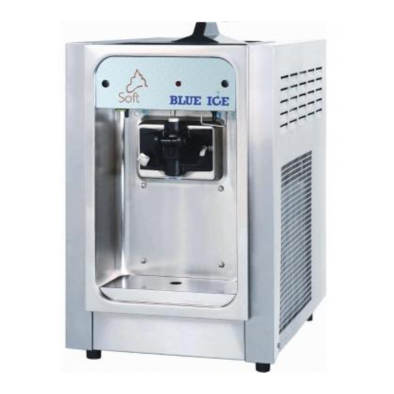
Air Cooled Units
The model T15 ice cream machine's air cooling unit require a minimum of 15.2cm of
clearance around both sides. Install the skirt provided on the right side of the unit and
place the back of the unit against a wall to prevent recirculating of warm air.
Electrical Hook-Up Installation For 50 Hertz, 1 Phase, Supplied With Cord and
Plug
This equipment is supplied with a 3-wire cord and grounding type plug for connection
to a single phase, 50 hertz, branch circuit supply. This unit must be plugged into a
properly grounded receptacle. The cord and plug provided for 230Volts, 50Hertz,
1Phase, is 8 Amp; therefore the wall outlet must also be 8 Amp. Check the data label,
located in the side panel, for electrical specifications. The plug should be accessible
after installation.
If the supply cord is damaged, it must be replaced by the manufacturer, its service
agent or similarly qualified person in order to avoid a hazard.
Permanent wiring may be employed if required by local codes. Instructions for
conversion to permanent wiring are as follows:
1. Be sure the freezer is electrical disconnected.
2. Remove the appropriate panel and locate the small electrical box at the base of
the freezer.
3. Remove the factory-installed cord and strain relief bushing.
4. Route incoming permanent wiring through hole in base pan.
5. Connect two power supply leads. Attach ground (earth) wire to the grounding lug
inside the electrical box.
6. Be sure the unit is properly grounded before applying power.
Electrical Connections for Models Without Cord and Plug Supplied
Each freezer requires one power supply for each data label. Check the data label on
the freezer for fuse, circuit ampacity and electrical specifications refer to the wiring
diagram provided inside of the control box, for proper power connections.
This equipment is intended to be installed in accordance with the National Electrical
Code. The purpose of this code is the practical safeguarding of persons and property
from hazards arising from the use of electricity. This code contains provisions
considered necessary for safety. Compliance therewith and proper maintenance will
result in an installation essentially free from hazard!
CAUTION: THIS EQUIPMENT MUST BE PROPERLY GROUNDED! FAILURE TO
DO SO CAN RESULT IN SEVERE PERSONAL INJURY FROM ELECTRICAL
Page 1
To the installer
Advertisement
Table of Contents
Troubleshooting

Summary of Contents for Blue Ice T15
- Page 1 To the installer Air Cooled Units The model T15 ice cream machine’s air cooling unit require a minimum of 15.2cm of clearance around both sides. Install the skirt provided on the right side of the unit and place the back of the unit against a wall to prevent recirculating of warm air.
-
Page 2: Mix Information
This Operator’s Manual should be read before operating or performing any maintenance on your equipment. The Model T15 will NOT eventually compensate and correct for any errors during the set-up or filling operations. Thus, the initial assembly and priming procedures are of extreme importance. -
Page 3: To Operate Safely
Page 3 Section3 Safety Extra caution should be taken when in contact with freezer and parts.We have gone to extreme efforts to design and manufacture built-in safety features to protect both you and service technician. IMPORTANT - Failure to adhere to the following safety precautions may result in severe personal injury. -
Page 4: Operator Parts Identification
Page 4 Section4 Operator Parts Identification Item Description Part No. Item Description Part No. Hopper Cover Assembly T15000030 11 Decal T15000005 Standpipe T15000001 12 Hold-Drip Pan T15020301 Mix Level Probe T15020430 13 Splash Shield T15000006 Top Panel T15020440 14 Drip Tray T15000007 Back Panel T15000002... - Page 5 Page 5 Section4 Operator Parts Identification Dispensing Door and Beater Assembly ITEM Part Number QTY. Description T15020703 Seal O-Ring T15020710 Beat T15020702 Front Bearing T15020501 O-Ring T15020610 Dispensing Door T15020504 O-Ring T15020503 Draw Valve T15020505 Valve Lifter Arm T15020506 O-Ring T15020507 Draw Valve Handle T15020508...
- Page 6 Page 6 Section5 Important: Operating Control Before operating the freezer, it is required that the operator knows the function of each operating control. Item Description Part No. Power Switch T1507C201 Spigot Switch T15070103 Mix Refrigeration Switch T1507C201 Reset Switch T1507C202 Indicator Light- "Mix Low"...
- Page 7 Page 7 Section5 Important: Operating Control A. Power Switch The center position is “OFF”. The left position is “WASH” which activates the beater motor only (Figure 5-1). The Power switch’s position is “ON” (Figure 5-2) which activates the beater motor and the refrigeration system. Figure 5-2 Figure 5-1 B.
- Page 8 Page 8 Section5 Important: Operating Control D. Reset Switch The reset switch is located under the control panel of the machine. When operate the machine first time after connecting or re-connecting the power, you must push the reset switch first, and then place the power switch. Otherwise, the power switch is not available.
-
Page 9: Operating Procedures
Page 9 Section6 Operating Procedures The machine has been selected to illustrate the pictured step-by-step operating procedures. It has a 1.7liter capacity freezing cylinder. The mix flows by gravity from the hopper to the freezing cylinder through an air tube. This machine is a counter model with a single spout door. - Page 10 Page 10 Section6 Operating Procedures Step 3 Install the dispensing door (Figure 6-4). Insert the hand screws into the slots in the dispensing door. With both hands, hold the sides of the beater assembly. The white guide bearings must fit securely in the holes of the drive shafts.
- Page 11 Page 11 Section6 Operating Procedures Step 6 (Figure 6-7) Snap the design cap over the bottom of the dispensing door spout. Figure 6-7 Step 7 (Figure 6-8) Lay the air tube in the bottom of the mix hopper. Figure 6-8 Sanitizing Step 1 Prepare 3.8 liters of an approved 100PPM sanitizing solution.
- Page 12 Page 12 Section6 Operating Procedures Step 6 Place an empty pail beneath the door spout and raise the draw valve. Draw off all of the sanitizing solution. When the sanitizer stops flowing from the door spout, lower the draw valve and place the power switch in the “OFF” position. Step 7 With sanitized hands, stand the air tube in the corner of the mix hopper.
-
Page 13: Closing Procedure
Page 13 Section6 Operating Procedures Closing procedure To disassemble this machine, the following items will be needed: Two cleaning pails Sanitized stainless steel rerun can with lid Necessary brushes Cleaner Single service towels Draining product from the freezing cylinder Step 1 Place the power switch in the “OFF”... - Page 14 Page 14 Section6 Operating Procedures Cleaning Step1 Prepare 3.8 liters of an approved cleaning solution. USE WARM WATER AND FOLLOW THE MANUFACTURE’S SPECIFICATIONS.. Step 2 Pour the 3.8 liters of cleaning solution to the mix hopper and allow it to flow into the flow into the freezing cylinder.
- Page 15 Page 15 Section6 Operating Procedures IMPORTANT: Follow label directions, as too STRONG of a solution can cause parts damage, while too MILD of a solution will not provide adequate cleaning. Make sure all brushes are available for brush cleaning. Step 2 Remove the O-rings from the drive shaft of the beater assembly.
- Page 16 Page 16 Section7 Important: Operating Checklist Product hardness adjustment Step 1 BE SURE THE POWER SWITCH IS IN THE “OFF” POSITION. Step 2 The hardness adjustment switch is located under the decorative panel. Remove the decorative panel, find a P. C. board. On the left-top side of P. C. board, find a 6-position switch.
-
Page 17: During Cleaning And Sanitizing
Page 17 Section7 Important: Operating Checklist During cleaning and sanitizing Cleaning and sanitizing schedules are governed by your State or local regulatory agencies and must be followed accordingly. The following check points should be stressed during the cleaning and sanitizing operations. WE RECOMMEND DAILY CLEANING AND SANITIZING. -
Page 18: Regular Maintenance Checks
Page 18 Section7 Important: Operating Checklist Regular Maintenance Checks 1. Check the rear shell bearing for signs of wear (excessive mix leakage in rear drip pan) and be certain it is properly cleaned. 2. Check the rear shell bearing for signs of wear (excessive mix leakage in rear drip pan) and be certain it is properly cleaned. -
Page 19: Troubleshooting Guide
Page 19 Section8 Troubleshooting Guide PAGE PROBLEM PROBABLE CAUSE REMEDY REF. a. The power switch is in the a. Place the power switch No product “OFF” position. and mix ref. swithc in being b. The mix level is the “ON” position dispensed inadequate in the mix b. - Page 20 Page 20 PAGE PROBLEM PROBABLE CAUSE REMEDY REF. a. Operating freezer a. Install the front bearing The freezing without the front bearing on the dispensing door. cylinder walls on the dispensing door. are scored. b. The gear unit or the b.
-
Page 21: Parts Replacement Schedule
Page 21 Section9 Parts Replacement Schedule Part Description Every 3 Months Quantity Beater Drive Shaft O-ring Dispensing door O-ring Dispensing door Front Bearing Draw Valve O-ring Draw Valve Handle O-ring Section10 Electrical Drawing The electrical drawing is in next page. ITEM Part Number QTY. - Page 22 Page 22 ÁϲۿÇÌå W22 W22 L1 L2 L3 L1 L2 L3 T1 T2 T3 T1 T2 T3 1 2 3 4 5 6 7 8 9 10 Reset Button Spigot Switch S2£º Power Switch Q1£º Mix Refrigeration Switch Transformer T1£º Indicator Light "Mix Low"...
Need help?
Do you have a question about the T15 and is the answer not in the manual?
Questions and answers