Table of Contents
Advertisement
Quick Links
USER MANUAL
TECHNICAL MANUAL
PARTS LIST
MMO 6000
Version 3
18/11/2016 DOC 1521013
Modifications – Version 3.2 - 29/06/2018
Brake pads cleaning : page 14
Brake module : spring of the mechanism : page 31
Warranty conditions page 36
Translation correction All pages
Spare part list Update : pages 41 to 52
Page 1 sur 68
Advertisement
Table of Contents

Summary of Contents for MMO+ MMO 6000
- Page 1 USER MANUAL TECHNICAL MANUAL PARTS LIST MMO 6000 Version 3 18/11/2016 DOC 1521013 Modifications – Version 3.2 - 29/06/2018 Brake pads cleaning : page 14 Brake module : spring of the mechanism : page 31 Warranty conditions page 36 Translation correction All pages...
-
Page 2: Table Of Contents
Sommaire Symbols used in the manual ..................4 Intended use of the bed ................... 5 General information ....................5 General precautions for use ..................6 Potential Risk of Entrapment ................7 Transport and storage ..................8 Installation and commissioning ................8 Identification of labels .................. - Page 3 Patient Lifting Pole ..................35 IV pole ......................35 Remote and Hand control holder ..............36 Warranty and Installation ..................36 Warranty ......................36 10.1 10.2 Installation and commissioning ................. 37 After sales service ....................38 11.1 Troubleshooting ....................38 11.2 Conditions of on-site assistance and spare parts supplies ........
-
Page 4: Symbols Used In The Manual
Symbols used in the manual Warning, please read this instruction regarding safety. Index of waterproof resistance of the electrical components Protection against electric shock. Type B device according to EN 60 601-1 DC power AC power 250 kg: Symbol safe working load of 250kg 220 kg: Symbol maximum patient weight of 220 kg (ca. -
Page 5: Intended Use Of The Bed
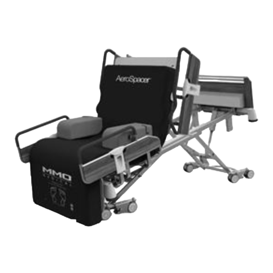
This bed meets the requirements of NF EN 150 10993. The mattress used must also meet the requirements of this standard. The MMO 6000 is available with an integrated AeroSpacer mattress in the UK and EIRE. Page 5 sur 68... -
Page 6: General Precautions For Use
General precautions for use The use and handling of a medical bed can cause injury. It is essential that the person who is handling the bed is authorized and trained. This person must know the consequences of all actions and how not to cause involuntary movements. Any maintenance must be performed by qualified personnel. -
Page 7: Potential Risk Of Entrapment
IT IS STRONGLY RECOMMENDED NOT TO: Use accessories that do not come from the manufacturer of without a specific agreement Pass the power cord into the moving parts of the bed or castor areas (to avoid entrapment or damage) ... -
Page 8: Transport And Storage
4.2 Transport and storage The bed is designed to operate at a temperature between 5°C and 40°C. These conditions should be applied during storage and transport. For transport the deck must be flat in the low position and all functions must be locked and the wheels braked. The bed should be protected from impact and friction. - Page 9 Label: risk of crushing the foot Label: risk of crushing fingers For 3 bars side rail, mattress max thickness is 17 cm For 4 bars side rail, mattress max thickness 26 cm Width of mattress : 90 cm Length of mattress: 200 cm Unused connections are sealed to prevent damage from electrostatic discharge.
-
Page 10: Warranty Terms / After Sales Service
The bed comes with a simplified user guide 4.5 Warranty terms / after sales service Our metal frames are guaranteed for a period of 10 years. Excluded from this warranty: all electromechanical parts (motors, gas and electric actuators, remote control, hand pendant, wheels, hospital beds, thermoformed plate). -
Page 11: General Cleaning Of Bed
General Cleaning of Bed The bed is not designed for automatic cleaning but only for manual cleaning only 5.1 Recommendations Whenever cleaning bed, advisable follow following recommendations: Unplug the bed and lock all functions if the bed is equipped with a battery (if the bed is unplugged, check that the plug does not come into contact with liquids). - Page 12 Cleaning or disinfection of a medical bed, although not in direct contact with the patient • and in particular damaged areas, should be cleaned regularly. Certain areas of the bed are more subject to contamination given the frequency of contact with carer’s and patient’s hands.
- Page 13 Use a swab and the detergent/disinfectant solution approved by the establishment. • Put the bed in the flat position and the bed base at the pelvis position (using the neutral • position control if the bed has one), unplug the bed and lock all electrical functions, unlock the brake, move the bed away from the wall to give access all around the bed, and reapply the brake.
-
Page 14: Bed Features
Unlock the brakes, reposition the bed against the wall, lock the brakes and clean the • brake control bar Reconnect the bed to the main control power supply, unlock the electrical functions • and return the bed to the flat position using the control handle. Clean the mattress and replace it on the bed. -
Page 15: Symbols & Pictograms Of Remote Control
NUMBER NAME Backrest Thigh section Calf section Footboard Headboard Brake pedal CPR handle Split siderail handles Symbols & pictograms of remote control Infrared remote control .Hand pendant 5 functions with lockout function CPR electric Backrest Backrest Thigh rest Height Thigh rest Comfort position Comfort position Trendelenburg... - Page 16 Control panel at the foot of the bed for caregiver with central lockout Thigh Comfort Height rest position Trendelenburg/ Backrest Reverse Trendelenburg Battery led Under bed light Lockout Lockout CPR Electric Set Patient exit height NOTE: The wireless remote control is universal. It allows controlling of all MMO 2000, 3000, 5000, 6000 or 8000 beds to the extent that they are equipped with the infrared receiver.
-
Page 17: Accessories
Handset with mechanical lock function Condemnation is a mechanical device that acts only on the hand pendant. The remote control, always allows the use of the locked function. For electric locking, use the caregiver’s control box at the foot of the bed. Caregiver control with... -
Page 18: Removal Of Head/Foot Board
A set of screws can provided for that purpose. Split siderails The MMO 6000 bed can be equipped with metal split side rails. These are positioned on the bed in compliance with safety clearances required by the regulations and to avoid the risk of jamming. -
Page 19: Product Description
Product description Standard equipment Front exit Split siderails folding outwardly and dampened Variable height and electric backrest Backrest articulation of 23 cm, designed to reduce sheer on skin of patient Electric knee break, with manual calf section Hand pendant with selective lockout of functions Four support of IV pole 4 double castor 100mm wheel directional in head 4 double castor 100mm wheel with centralized braking system on foot... -
Page 20: Dimensions
7.1 Dimensions Dimensions Observations Height of deck in high position 83 cm (castor Ø 100mm) Height of deck in low position 31 cm (castor Ø 100mm) Total lenght 214 cm Width with 99.8 cm Width with folding siderail 99,8 cm Height of siderail on the deck 38 cm Height of headboard and footboard... -
Page 21: List Of Parts Covered By Iso 60601
250 kg (215 kg patient, 20 kg mattress and 15 kg Safe working load accessories mattress) 8 wheels 100mm diameter directional wheels on Basic wheels head and the foot, central braking Hydraulic shock absorber for backrest ELECTRIC Supply voltage 100-240 VCA frequency 50-60Hz Recommended Service ratio... -
Page 22: Maintenance Specification For Electronic Parts And Actuator (Linak)
IV pole • Castors • Brake pedals • 7.4 Maintenance specification for electronic parts and actuator (LINAK) Maintenance: valid for all products LINAK • LINAK products must be cleaned at regular intervals to remove dust and dirt, and must be inspected for any damage, wear and breakage. -
Page 23: Use Of Different Product Features
Operating: If you encounter noise coming from the actuator during use, it is recommended to stop using the bed and investigate. If you encounter any noises or strange smells coming from the control box, immediately disconnect the bed from the mains power supply and / or batteries. ... -
Page 24: Articulation Of The Bed Deck
Press the left side of the button to go up or right side to go down to the desired height. Warning: for irregularly monitored patients, it is advisable to leave the bed in a low position to reduce the risk of injury in case of falls. Under certain circumstances it may be necessary to prevent operation of the bed controls, therefore we recommend you use the lockout functions on the hand control. -
Page 25: Operating The Safety Flattening Of The Bed When The Power Supply Is Cut
8.2.2 Operating the safety flattening of the bed when the power supply is cut The following operation should be performed when the bed is unoccupied and without mattress. The electrical backrest will become inoperative. Lower barriers if they are raised. Remove a clip on the top axis of the actuator of the backrest. -
Page 26: Electrical Thigh Section And Manual Calf Section
8.2.4 Electrical thigh section and manual calf section This function allows you to electronically set the thigh section and manually set the calf section. The angle of the thigh section ranges from 0° to 30°, and the calf section ranges from +/- 20° (see drawing below). -
Page 27: Storing The Bed Exit Height Into The Electronic Memory
8.2.6 Storing the bed exit height into the electronic memory This function allows you to adjust the height of the exit position to the height of each patient. This assures perfect ergonomics, reduces the effort to exit the bed and reduces the risk of falling. -
Page 28: Trendelenburg/Reverse Trendelenburg Position
Make sure the straps are secure and do not interfere with the movement of the side rails. Before doing front exit, make sure you have enough space at the foot of the bed for the maneuvers. Ensure that the flexibility of the mattress allows a perfect follow-up of the important movement of the bed deck Once secured to the bed by the straps, make sure that the mattress cover is •... -
Page 29: Under Bed Night Light
8.2.10 Under bed night light The night light switches an LED on under the bed platform to assist the patient getting in and out of the bed at night Operation: to operate the under bed night light is by simultaneously pressing the bed and knee lowering buttons on the hand control. -
Page 30: Wall Protection And Position Indicator (Option)
8.2.11 Wall protection and position indicator (option) The bed is equipped with 4 corner bumpers to absorb shock. The bed also incorporates a retractable visual indicator with automatic return, integral brake system serving as a position indicator to prevent the moving parts of the bed to contact the wall at the bed's angular movement. -
Page 31: Brakes
8.3 Brakes The bed is equipped with brakes acting on the wheels in front and back of the bed. Operation: To use the brake press on each trigger that is on the wheels. To unlock the brakes, tilt them back up with the tip of your foot. According to the standard 60601-2-52 braking the bed is certified up to an angle of 6 °... -
Page 32: Transferring The Patient In The Bed
8.4 Transferring the patient in the bed The MMO 6000 is equipped with directional wheel on the head of the bed. This helps moving around tight corridors or on long distances with or without the patient. Operation: If the bed has the multidirectional wheel at the head, put brakes on head wheels. -
Page 33: Reset Procedure
Patient Strap positions Deck with electrical tight movement and mechanical legs movement 8.7 Reset procedure An audible warning indicates that the bed is not functioning as intended. In this case you must follow this calibration procedure: press the variable height Up and Down buttons simultaneously for a minimum of 5 seconds. -
Page 34: Accessories
Caution: when the bed is set at the lowest position the bottom of the side rail could touch the floor. This should not cause harm to patient or caregiver. Accessories 9.1 Gap filler This accessory permits to fill the space between the side rail and the footboard The side rail can be removed even if the gap filler is in position. -
Page 35: Flexible Holder For Hand Pendant
9.3 Flexible holder for hand pendant Flexible holder for hand pendant with clamping knob (the TEE59981E supports is required if you want to fix it the middle of the bed) 9.4 Siderail padding This padding covers the side rail to avoid injury to the patient, and reduces the risk of entrapment between the side rail bars Operation: fit the cover over the top of the raised side rail, then secure in place. -
Page 36: Remote And Hand Control Holder
Identification label is near the hook Remote and Hand control holder These accessories are here to store the remote control and hand control. The remote holder has glue pad on the back to stick to most surfaces. It also has 2 holes to screw it to the wall A flexible hand control support (TEE59983G) is also available. -
Page 37: Installation And Commissioning
approved maintenance programme is in place utilising approved OEM parts and that the product is not subject to use beyond the manufacturer’s guidelines and normal wear and tear. For UK and EIRE customer, if no service contract is in place within the first year of purchase, the warranty will revert to two years only. -
Page 38: After Sales Service
Grid Connection: Make sure the power supply complies with current safety standards, especially as the supply voltage is 100-240 VCA + / - 10V; 50-60 Hz. The bed is equipped with an electrical protection class I (grounded). The ground connection is essential. Check that the AC outlet is properly connected to the ground. -
Page 39: Bed Identification Label
estimate or an order form must be signed and returned before any after-sales services are provided. After-Sales Service (ASS) is provided by the manufacturer, or by a manufacturer-approved technician. Spare parts will be shipped from factory within 48 hours from the receipt of orders. If the part is not in stock, or if it is not included in the list of spare parts, our ASS will inform you of the delay required for supply. -
Page 40: Exploded View Of The Bed
12 Exploded view of the bed Head board Foot split siderail Head split siderail Foot board Multidirectionnal Wheels Ø 100mm Page 40 sur 68... -
Page 41: List Of The Spare Parts
13 List of the spare parts Page 41 sur 68... - Page 42 SPARE PARTS MMO 6000 FO_QA_012 BASE DESCRIPTION DRAWING NR PREPARED HEAD ROLLER RP5T6491 600190-5EA5 SUPPORT PREPARED FOOT ROLLER RP5T6487 600191-5EA5 SUPPORT PREPARED ELEVATION ARM RP5T7082 SMALL COMPENSATION RP5F4750 208008-5EA5 CONNECTING ROD RP5T7084 208113-5EA5 ASSEMBLED BRAKE PEDAL SPIDER ROLLER RP5F1672 147913...
- Page 43 SPARE PARTS MMO 6000 FO_QA_012 PREPARED HEAD ROLLER SUPPORT DESCRIPTION DRAWING NR RP5F7546 208078-5EA5 ROLLER SUPPORT ROLLER SUPPORT PLATE RP5F7565 208079-5EA5 SWIVEL CASTOR Ø100 S-BRAKE QC9F8169 200032 CHC SCREW QC9F8170 200033 HFR NUT QC9D8148 9028 HEXAGON NUT COVER QC9F6172 209535...
- Page 44 SPARE PARTS MMO 6000 FO_QA_012 PREPARED HEAD ROLLER SUPPORT DESCRIPTION DRAWING NR RP5F7546 208078-5EA5 ROLLER SUPPORT ROLLER SUPPORT PLATE RP5F7565 208079-5EA5 SWIVEL CASTOR Ø100 S-BRAKE QC9F8169 200032 CHC SCREW QC9F8170 200033 HFR NUT QC9D8148 9028 HEXAGON NUT COVER QC9F6172 209535...
- Page 45 MMO 6000 SPARE PARTS FO_QA_012 LEG REST DESCRIPTION DRAWING NR ASSEMBLED THIGH REST RP5T6560 41600-5EA5 #REF! RP5T6948 TELESCOPIC LIFT-UP FITTING QC9D2460 12992 10,70 € RP5T6946 ELECTRIC SCREW LIFTING JACK QC9T2720 141290 97,50 € BUNCHED CONDUCTOR QC9T7283 42005 #REF! ACTUATOR POWER CABLE...
- Page 46 SPARE PARTS MMO 6000 FO_QA_012 HEAD HALF-BARRIER DESCRIPTION DRAWING NR 1/2 PREP LEFT HEAD BARRIER RP5T6908 600145 1/2 PREP RIGHT HEAD BARRIER RP5T6909 600144 RP5S9843 ASSEMBLED SINGLE ARM RP5S9555 41850-5ET5 LOCKING COMMAND RP5D9945 40184 RP5T6792 TUBE PIROGUE RP5D9947 40182 REAR HUB CAP...
- Page 47 SPARE PARTS MMO 6000 FO_QA_012 FOOT HALF-BARRIER DESCRIPTION DRAWING NR 1/2 PREP LEFT FOOT BARRIER RP5T6914 600142 1/2 PREP RIGHT FOOT BARRIER RP5T7440 600143 RP5S9843 ASSEMBLED SINGLE ARM RP5S9555 41850-5ET5 LOCKING COMMAND RP5D9945 40184 RP5T7359 TUBE PIROGUE RP5D9947 40182 REAR HUB CAP...
- Page 48 MMO 6000 SPARE PARTS FO_QA_012 BACKREST DESCRIPTION DRAWING NR RP5T4645 HYDRAULIC SHOCK ABSORBER C QC9S9825 39137 220 mm ASSEMBLED COUNTER-ROD RP5T6738 41890-5EA5 RP5T7236 41893-5EA5 ASSEMBLED BACKREST Page 48 sur 68...
- Page 49 SPARE PARTS MMO 6000 FO_QA_012 FRAME DESCRIPTION DRAWING NR BED EXTENTION FRAME RP5T6501 41830-5EA5 CENTRAL SECTION ASSY RP5T6510 41820-5EA5 LEFT FOOT SPLIT SIDERAIL RP5T6915 600143 RP5T6914 600142 RIGHT FOOT SPLIT SIDERAIL LEFT CORNER FITTING RP5D9363 39108 AT5D6557 19291 STOP Ø 100...
- Page 50 PIECES DETACHEES MMO 6000 FO_QA_012 SPARE PARTS SLEEP DECK DRAWING NR DESCRIPTION BACKREST SLEEP DECK RP5T7072 600137 FIX SECTION SLEEP DECK RP5T7073 600138 RP5T7248 RP5T7249 MATTRESS RETAINER RP5F7702 250727 QC9F8898 67304 RUBBER BUNG Page 50 sur 68...
- Page 51 MAINTENANCE GUIDE FOR MEDICAL BEDS Levels 1 & 2 Page 51 sur 68...
-
Page 52: Maintenance Guide For Medical Beds Levels 1 & 2
14 Maintenance guide for medical beds Levels 1 & 2 14.1 Manufacturer’s commitment: Warranty: Furniture: 10 years guaranteed against defects or failure under normal use conditions. Mattresses: guaranteed 2 years Electromechanical parts (engines, gas and electric actuators, remote controls, wheel of medical beds, thermoformed plates) ) see Warranty paragraph 10 HOTLINE 0811-900-035 a specialized staff is ready for you 24/7 - 365/365 days... - Page 53 Personal notes Page 53 sur 68...
-
Page 54: Preventive Maintenance
14.3 Preventive maintenance Only authorized trained staff may perform the maintenance tasks described in this chapter. Unauthorized or untrained staff may risk injury or electrical shock. Before carrying out any necessary maintenance tasks ensure the bed is disconnected from the mains power supply and that lock-out functions are disabled. - Page 55 Check List Medical Bed Identification of medical device Hospital Category: MEDICAL BED Brand/Model/Type: MMO 5000 Serial n° : Department / Location: Date of Manufacture: Qualitative aspects NA YES NO Operational and visual checks OVERALL CONDITION Availability of user manual and technical manual Good overall condition (bed ends, protecting buffers, bed platforms, castors…) Acceptable level of corrosion with regard to user service requirements Satisfactory condition of identification tags / labels / screen-printing...
- Page 56 Safety check NA YES NO Operational function lockout Functionality of emergency lowering function (CPR) Satisfactory load resistance of the motors Correct operation of visual and sound alarms Quantitative aspects NA YES NO Satisfactory battery-operation of bed Check to ensure the height of the side rail at the top of the non-compressed mattress complies with the standard in force, which is 22cms AMPLITUDE OF MOVEMENTS Back rest : Maximum angle according to manufacturer’s specifications...
-
Page 57: Servicing
15 Servicing Only authorized trained staff may perform the maintenance tasks described in this chapter. Unauthorized or untrained staff risk injury or electrical shock. Before carrying out the necessary maintenance tasks, and after having put the bed into the required position, if the bed is equipped with backup batteries, it must be unplugged from its power source and all its electrical functions must be locked- out. - Page 58 The bed operates via the carer control unit NO → Step 7 YES → Steps 5 and 6 5 Check the condition of the patient control unit power supply wire and check that it is connected to the power supply unit. 6 Disconnect the patient control unit and try using a different one (refer to wiring diagram).
-
Page 59: Second Level - Wiring Diagram
Fatal Error (error detected in one or more cylinders): Simultaneously press the 2 buttons on 2nd line of the hand pendant. An intermittent signal sounds, maintain pressure until disappearance of the signal. Replace the high maximum position and then bed down in the down position. - Page 60 WIRING DIAGRAM SPARE PARTS MMO 6000 This diagram is shown on the cover of the power supply unit. The wires are fitted with FO_QA_012 numbered rings so that their position may be identified on the terminal block.
-
Page 61: Replacement Of The Patient Hand Pendant(Refer To Wiring Diagram)
15.2.1 Replacement of the patient hand pendant(refer to wiring diagram) Raise the bed to the maximum height position (if possible), then unplug the bed from the power supply. Remove the central section of the bed platform to access the power supply unit. ... -
Page 62: Replacing The Castors
Caution: This procedure requires special precautions as the variable height motor connects the main frame assembly to the bed platform. If the bed is set at a raised position, support the bed platform before disconnecting the actuator. 1. Remove all the sections from the bed platform. 2. -
Page 63: Data
Some installation precautions may be necessary such as moving equipment or installation in a protected enclosure. Manufacturer’s guide and declaration- electromagnetic emission The MMO 6000 bed is to be used in the electromagnetic environment described below. The user must ensure that it is used in this environment Emissions test... - Page 64 ± 2 kV for the ± 2 kV for the The quality of the main supply Rapid supply lines supply lines should be that of a typical transient burst ± 1 kV for commercial or hospital ± 1 kV for EN 61 000-4-4 input/output environment.
- Page 65 MMO6000 medical bed is designed to be used in the electronic environment specified below. The user must ensure it is used in accordance to these guidelines Page 65 sur 68...
-
Page 66: Disposal At End Of Product Life
Recommended separation distances between portable Radio Frequency communications equipment and mobile equipment The hospital bed is intended for use in an electromagnetic environment In which radiated RF disturbances are controlled. Users of hospital bed can help prevent electromagnetic interference by maintaining a minimum distance between the bed and RF communications equipment (transmitters) and the hospital bed as recommended below, according to the maximum output power equipment communication. - Page 67 Page 67 sur 68...
-
Page 68: Manufacturer's Detail
17 Manufacturer’s detail SOCIETE MMO 24, Route de Beauvais BP 90148 35501 VITRE Cedex France Tél. : +33(0)2 99 75 04 50 – Fax : +33(0)2 99 74 65 71 For further information relating to technical characteristics, maintenance or After Sales Service, please consult the bed’s technical manual available on request from MMO.
Need help?
Do you have a question about the MMO 6000 and is the answer not in the manual?
Questions and answers