
Summary of Contents for Tokai Hit Thermo Plate TPi Series
-
Page 1: Table Of Contents
MA-TPi-EN-01 Microscope-Stage Automatic Thermocontrol System TPi series Instruction Manual Index For safe and comfortable use Components and names Display and parameter p.10 Preparation for use p.13 How to use p.17 PID calibration p.19 Shift calibration p.20 Key lock setting p.21 TEM –... -
Page 2: For Safe And Comfortable Use
1. For safe and comfortable use Be sure to read this instruction manual carefully before using, and please use the device correctly. Also, please keep this instruction manual. For your safety If device is used in manner other than specified in instruction manual, safety cannot be assured and may result in damage to device which will not be covered under warranty. - Page 3 Regarding on the environment for usage and storage Do not use this equipment in the below conditions. Flammable or corrosive gas or oil mist that can damage electrical insulation Intense vibration or impact High voltage power lines, inductive interference Place where dew drops are present or with direct sunlight Dusty place Outside the designated use environment and storage environment Points to pay attention when installing to a microscope...
- Page 4 Please observe the below in order to avoid focus drift during microscope observations. Keep the room temperature at 25℃±2℃. Do not let air flow directly over the device. In an emergency pull out the plug from the outlet. Do not place any things near the outlet.
-
Page 5: Components And Names
AC Adapter (Length:1800mm) Supplies power to the controller * Must use in original pairs Power Cable (Length:1800mm) Installs Tokai Hit original data logging (Temp. logging software) software. The data will be saved as Installation CD CSV format Cable connected between the... - Page 6 Controller Dimension of Controller (Excluding protrusions): W85×D135×H30 mm Display SET Key UP Key Screen Shift Key DOWN Key Stand-by Switch Plate Connector Power Supply Connector Sensor Connector Hook Mounting Hole USB Connector Name Plate Name Plate(Sample) For details, please refer to the actual name plate attached on the product. Serial Number Model Name...
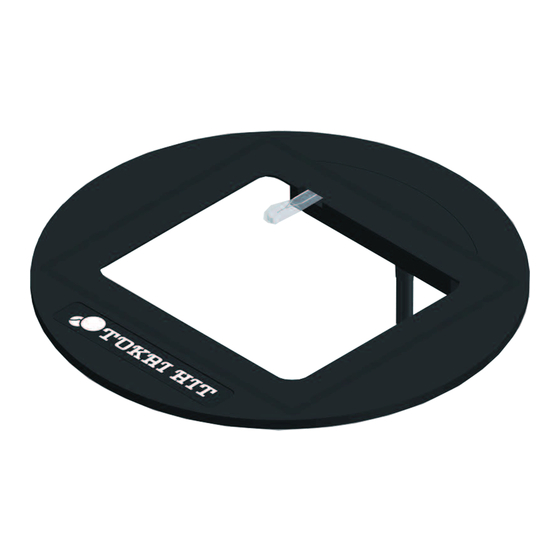
- Page 7 Glass Heater * Plate Lamp is attached to some major models. TPi-110RX φ110mm Inverted Plate Dimension: TPi-108RX Fixing Spring φ108mm Glass Heater Plate Dimension: TPi-URI2X φ110mm Plate Dimension: Plate Sensor * Exclusively designed for Integra 3 (not compatible to use with Integra Ti) Plate Lamp Plate Cable TPi-SQFTX...
- Page 8 Glass Heater * Plate Lamp is attached to some major models. TPi-SZX2AX TPi-SZX2BX Stereo Stereo 238×227mm 222×240mm Plate Dimension: Plate Dimension: Spot Facing for Spot Facing for Plate Lamp Mounting Screw Mounting Screw ( Please use the ( Please use the attached screws )...
- Page 9 ⇒ Hole diameter is 10mm Model:TPi-110RH10, TPi-SQH10FT 2 in 1 Heater TPiD-I2X Inverted 160×110mm Plate Dimension: Metal Heater Glass Heater * 2 channel controller is included Some models are not listed in this manual. For details, please contact Tokai Hit.
-
Page 10: Display And Parameter
3. Display and parameter Operation key / Display ⑥ ① ② ③ ④ ⑤ ⑦ ⑧ ⑨ ⑪ ⑫ ⑩ 1) SET enter button 1 SET Key 2) Starts PID Calibration by pressing and holding the button For details, refer to 6. PID Calibration (p.19). 1) Shift the screen 2... - Page 11 Plate Lamp condition * Plate Lamp is attached to some major models. Plate Lump Plate temp. process value (PV) = Plate temp. setting value (SV). Lights when“the plate temp. process value (PV) = plate temp. setting Lights up value (SV)”condition lasts longer than 5 seconds. Turns off when the plate temp.
- Page 12 Parameter (Press and hold) Stand-by(Display OFF・Control STOP) All states Main Display User Mode Plate 1 Temp. of Plate 1 Shift Value By setting the shift value to zero, you can restore the factory default settings. Password Temp. of External Sensor To Engineer Mode To User...
-
Page 13: Preparation For Use
4. Preparation for use Installation ① Place the heating plate on the microscope stage. * For inverted microscopes, please be careful not to entangle the plate cable with objective lens. ② Connect the heating plate to the plate connector of controller. Since it is a lock type connector, please insert it... - Page 14 For measuring temperature Attach the External Temp. Sensor to the glass part of the Heating Plate. Please be sure to follow the procedure as follows: The adhesive tape should not touch the plate temp. sensor. Adhesive Attach the cable of the tape External Temp.
- Page 15 How to use the Mounting Hook You can use the controller as it is on the flat surface, or use in the following way with the attached Mounting Hook. ◎When placing the controller on the flat surface Attach the Mounting Hook as shown above. Please use it on a flat surface.
- Page 16 Setting Image (For measuring temp.) Plate Temp. AC Adapter Sensor DC24V Outlet AC100- 240V Heating Plate External Temp. Sensor Extension Wire (Auto-clavable) (USB Connection) For accurate temp. control Before using, be sure to confirm that the serial number stated in the product name plate on the back of the controller: ○○○○○○...
-
Page 17: How To Use
5. How to use ① Please turn on the Stand-by Switch and run preliminary operation. For the preliminary operation, please leave it for about 30 minutes to 1 hour. When you press the Stand-by Switch, heating starts. Do not touch the heater part beyond necessity while heating. - Page 18 ④ Set a dish on the Heating Plate and start observation. Examples of dish INCORRECT installation Dish is on the Sensor There is an object on Dish protrudes beyond the the Sensor heating surface It may cause sensor false detection, which There is a risk that the sample is not heated may affect temperature control.
-
Page 19: Pid Calibration
6. PID Calibration This system adopts PID control for stable temp. control, and the controller is calibrated under the environment of room temperature 25 ± 2℃ before shipping. If the temp. of the Heating Plate is not stable in your environment, the controller can calculate the optimum parameters according to your environment by carrying out PID calibration so that the Heating Plate temp. -
Page 20: Shift Calibration
7. Shift Calibration The Shift Calibration is for correcting temp. so that the surface temp. of the Heating Plate is equal to the temp. of the External Temp. Sensor measures. * Since the External Temp. Sensor is not included in the Economy Type, this operation can not be carried out. -
Page 21: Key Lock Setting
8. Key lock setting To prevent changing setting value accidentally, the system can be set the key lock. It enables to see main monitor but cannot change the values. Main Display Temp. of Plate 1 Setting can not be changed by key lock ON Temp. -
Page 22: Tem - Installation
9. TEM - Installation TEM (Temperature Logging Software) connects the controller and the PC by USB and graphically displays the measured values. In addition, since the measured data can be saved as CSV data, it can be used for quality control. ①... -
Page 23: Tem - How To Operate
10. TEM – How to operate ① Start the TEM(Temp. Logging Software). ② Select“Port setting”from“Setting”on the screen, select the communication port to which the device is connected, and click“OK”. * The communication port can be checked from“Device Manager”. ③ When connecting successfully, the following image will be displayed. Logging Logging Display... - Page 24 Logging method ③ Select“logging”button on the toolbar, you will get a dialog saying“Start logging”. Click“OK”to start logging. ⑤ If you want to stop logging, select the“logging”button on the toolbar will bring up the dialog“Stop logging”. Click“OK”to stop logging. ⑥ To check the logged data, click the“File”button on the toolbar to display a list of saved files.
-
Page 25: Trouble Shooting
OUT Lamp is ON. Abnormal heating found, DO NOT use the plate and detection contact Tokai Hit . In case of false The Heating Plate sensor detect detection, it will recover by turning on temp. elevation when controller OUT Temp. - Page 26 Basic Specification Method PID Control Increments 0.1℃ Setting method Digital switch using UP and DOWN key Maximum temp. setting 60.0℃ Minimum temp. setting 0.0℃ Controllable temp. Ambient+5℃ ~ 60.0℃ (TPi-UNIX:~ 50.0℃) Temp. accuracy Within 0.1℃ (Under room temp. 25℃, in our terms and conditions) Sensor Platinum resistance thermometer(Pt100Ω)...
- Page 28 306-1, Gendoji-cho, Fujinomiya-shi, Shizuoka Japan 418-0074 TEL: 0544(24)6699 FAX: 0544(24)6641 http://www.tokaihit.com Email: solution@tokaihit.com MA-TPi-EN-01...
Need help?
Do you have a question about the Thermo Plate TPi Series and is the answer not in the manual?
Questions and answers