
Subscribe to Our Youtube Channel
Related Manuals for COMBISAFE System Mk II


Summary of Contents for COMBISAFE System Mk II
- Page 1 Loading System MkII Including SkyReach Anchor USER INSTRUCTIONS 0158 - EN 795:2012-E...
-
Page 2: Table Of Contents
Recommended operating method ..............39 Single Unit usage ..................39 Double Unit usage ..................40 Maintenance ....................42 Check list prior to usage ................42 Cleaning ..................... 44 Recycling ....................44 © Combisafe International AB UI Loading System MkII-EN-1634 Subject to changes. -
Page 3: General
MkII Single Unit can be used. If unloading a trailer between 8 and 14 m in length, the Loading System MkII Double Unit should be used. Read carefully through this user instruction before use of the product. In case of questions and for clarification, please contact Combisafe for support. -
Page 4: Quick Guide
General Loading System MkII Quick Guide... -
Page 5: Safety Instructions
• When referring to any components of the system not produced by Combisafe, please refer to the specific user guide/manual for that item. - Page 6 Maintenance chapter which must be followed prior to use. Never combine products It is not recommended to install, combine or interconnect products other than those supplied by Combisafe. Combisafe product liability is limited to correctly installed Combisafe products only. Always use Personal Fall Protection Equipment Personal Fall Protection Equipment (PFPE) must always be worn during assembly and dismantling when a risk of falling exists, see Figure 1.
- Page 7 Loading System MkII Safety Instructions Fall clearance Note that it is essential to verify that adequate free height exists to the closest underlying object, please see Figure 2 below. Figure 2. Explanation of fall clearance. 0,7 [m] Maximum vertical deflection of the SkyReach Anchor Point Braking distance of the SRL.
-
Page 8: Remember
If an accident has occurred, e.g. a person falls, the items must be immediately withdrawn from use and inspected by a competent person according to the manufacturer´s safety check. Please contact Combisafe for more information regarding inspections and associated documentation. NOTE The SkyReach Anchor is designed to deform when a fall occurs, to absorb the energy and to reduce the resulting forces. -
Page 9: Technical Data
Loading System MkII Technical Data Technical Data Main Parts Figure 3. Main parts of the Loading System MkII with the SkyReach Anchor installed. Item Art no. Designation Weight 8800 Loading System MkII Base 250 kg 11468 Top Column 4.7 25 kg 8801 SkyReach Adaptor 5.9 27 kg... -
Page 10: Loading System Mkii Base
Technical Data Loading System MkII Loading System MkII Base When the Loading System MkII Base is equipped with the Top Column 4.7 or the SkyReach Adaptor 5.9 and loaded with ballast it is a CE certified attachment to be used as a housing for the SkyReach Anchor. Material: ........ -
Page 11: Top Column 4.7
(slings are not included). Material: ........Hot dip galvanised/painted steel Weight: ........25 kg Height: ........3,1 m Assembled width: ....... 2,0 m Packed width: ......0,2 m NB. Suitable slings are available from Combisafe, order code 100686... - Page 12 Technical Data Loading System MkII Figure 5. The SkyReach Anchor in assembled and folded mode. SkyReach Anchor Labels and Markings The Figure 6 below shows all the labels and markings of the SkyReach Anchor. The following figures (Figure 7, Figure 8 and Figure 9) are showing these important elements.
- Page 13 Loading System MkII Technical Data Figure 6. Labels and markings on the SkyReach Anchor. ID Plate Reflective Tape Anti Slip Grip Tape Insertion Marking Label 6 x Reflective Tape Combisafe Label Anti Slip Grip Tape Product Information Label...
- Page 14 Type B SKYREACH Anchor 0158 EN 795:2012 #8100 #8500 #8800 © Combisafe International AB 100583-1446 Type B #81 00 Type E Figure 8. Detailed view of the Product Information Label Manufacturer. Name of the product. Identification number of the notified body; DEKRA EXAM GmbH, responsible for CE production quality control.
- Page 15 Loading System MkII Technical Data Personal Fall Protection Equipment To create a complete system to protect the operative when working at height, the Loading System MkII needs to be equipped with Personal Fall Protection Equipment (PFPE). Figure 10 shows an example of how to equip the SkyReach Anchor with recommended PFPE.
- Page 16 Technical Data Loading System MkII Figure 10. The figure shows the SkyReach Anchor equipped with recommended PFPE. Item Part no. Designation Weight 8100 SkyReach Anchor 25 kg Full body harness certified to EN 361 CM1002889 Miller Extra Webbing, 0.3 m 0,2 kg CM1011729 Miller Falcon SRCL, 6.2 m 4 kg...
-
Page 17: Optional Items
Precast Kentledge (Art. 11655) This precast concrete block is one out of three possible ballast options, and can be ordered from Combisafe. Please see the following chapter Ballast for more information. Material: ........Concrete Weight: ........ - Page 18 Technical Data Loading System MkII Figure 11. Optional items. Item Part no. Designation Weight 11655 Precast Kentledge (2 pcs needed) 800 kg/pc 11446 Formwork Support (8 pcs needed) 11 kg/pc 11530 SkyReach Reach Hook 1,5 kg...
- Page 19 Loading System MkII Technical Data Ballast The Loading System MkII Base needs to be loaded with a minimum 1500 kg of suitable ballast to keep it stable and meet the requirements in the standard. The ballast can be applied in three different ways, which are presented below. Further details on how to perform the ballast loading procedures are described in the Assembly chapter.
-
Page 20: Assembly
Assembly Loading System MkII Assembly Assembling the Loading System MkII The following information and illustrations are a step by step guide on how to rig a Loading System MkII together with a SkyReach Anchor unit successfully. The Loading System MkII can be used with any of the three ballast options described. - Page 21 Loading System MkII Assembly Figure 12. Lifting the Bottom Frame with a fork lift truck. Figure 13. Adjustment of the Foot height with a 22 mm spanner. Place the four Corner Posts into the Bottom Frame, with the welding nuts facing outwards.
- Page 22 Assembly Loading System MkII Figure 14. Insertion of the Corner Posts. NOTE The lower edge of the Insertion Marking Label on the Corner Posts must be aligned with the upper edge of the Bottom Frame Posts for a safe and proper installation. See Figure 15 below for a closer illustration of the label.
- Page 23 Check that the two rear Corner Posts are inserted correctly, and the two front Corner Posts are left to one side. Use a forklift truck to place two 800 kg COMBISAFE Precast Kentledge onto the Bottom Frame, see Figure 16. When the concrete block is in place, place the two remaining Corner Posts into the Bottom Frame.
- Page 24 Assembly Loading System MkII 1325 1190 [mm] Figure 17. Dimensions for the bottom board. Figure 18. Example of placement of Formwork Support. Bottom Board...
- Page 25 Wooden Ribs leaning towards the Formwork Supports, see Figure 20. Make sure to place all the units overlapping so that all the sideboard units get the same support when leaning against the Formwork Supports. NB. Suitable base and side boards are available from Combisafe, order code 11595...
- Page 26 Bottom Frame. Bolt the eight Formwork Supports to the welding nuts. Use the bolts attached to the Formwork Support, see Figure 22. At this step it is not necessary to tighten the bolts. NB. Suitable base and side boards are available from Combisafe, order code 11594...
- Page 27 Loading System MkII Assembly 1325 1190 [mm] Figure 21. Dimension of the Bottom Plywood Board. Figure 22. Example of placement of Formwork Support. Bottom Board...
- Page 28 Assembly Loading System MkII 5.2 Cut four pieces of 18 mm formwork plywood, complying with EN 636-3, to the format as shown in Figure 23. Place the boards one after another in the Base, with the notches facing down, leaning against the Formwork Supports, see Figure 24.
- Page 29 Loading System MkII Assembly When using the SkyReach in the Loading System MkII unit, the Top Column 4.7 can be used to provide an anchor point located 4,7 m above ground level. If greater working height is preferred, then chose the SkyReach Adaptor 5.9 instead.
- Page 30 Assembly Loading System MkII Figure 26. Use the included Combistraps to secure the Top Frame to the forks prior to lifting. Lift the assembled top unit high enough above the Corner Posts, and slowly lower the assembly when the four Top Frame Legs can be slotted into the Corner Posts.
- Page 31 Loading System MkII Assembly Figure 27. Insertion of Top Frame to Corner Posts. Note the position of Insertion Marking Label when Top Frame is slotted into the Corner Posts in the illustration to the left. Now the Loading System MkII Base is completed as an assembled unit and equipped with either the Top Column 4.7 or the SkyReach Adaptor 5.9.
- Page 32 Assembly Loading System MkII Installation instructions for the SkyReach Anchor 10.1 Mount the SkyReach Anchor from the folded position in four easy steps, please see Figure 28: Remove the Lock Pin and release the SkyReach Anchor Brace and Boom. Arrange the position of the Boom. Move the SkyReach Anchor Brace and make sure that the brace hook bracket (detail A) fits into the lower lugs (detail B).
- Page 33 Make sure that the Lock Pin is properly installed, latch is dropped and that it is secured with the wire. Under no circumstances shall a substitute Lock Pin other than ones provided by Combisafe be used. 10.2 Connect the Fall Arrest Block. Make sure that the component is correctly attached and secured to the SkyReach Anchor point.
-
Page 34: Dismantling
Assembly Loading System MkII 10.3 It is recommended to attach the slings to the lifting eyes on the SkyReach. This slings will help correct positioning of SkyReach. The lifting eyes on the SkyReach Brace are not designed as anchorage points, avoid any usage other than stated in this User Instructions. 11. -
Page 35: Transportation
Loading System MkII Transportation Transportation If there is a need to move the Loading System MkII once the unit is assembled and loaded with ballast, it is important that it is handled the correct way to prevent lifting accidents. Use a fork lift truck, place the forks underneath the Base with the forks as wide as possible, see Figure 31. - Page 36 Transportation Loading System MkII Figure 31. Lifting the whole unit for transportation.
-
Page 37: Storage
Loading System MkII Storage Storage Always store Combisafe products in a dry and ventilated area protected from the effects of the weather and from corrosive substances. Loading System MkII Base The Loading System MkII is designed to ease storage when not in use. Since the units can be packed flat, it is easy to store them in a stack. -
Page 38: Skyreach Anchor
Storage Loading System MkII The flat packed version of the Loading System MkII must be always lifted with a fork lift truck, or equivalent vehicle, and the forks always be placed underneath the horizontal chords of the Bottom Frame, see Figure 33. Remember to only lift one unit at a time. -
Page 39: Recommended Operating Method
This method is based on a width of the flatbed loading area greater or equal to 2,4 m. For any width less than mentioned, please contact Combisafe for advice. The Base must be positioned centrally to the zone, as shown below. -
Page 40: Double Unit Usage
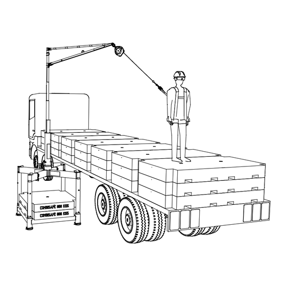
This method is based on a width of the flatbed loading area greater or equal to 2,4 m. By any width less than mentioned, or by flatbed length greater than 14 m, please contact Combisafe for advice. The operative must be connected to both Loading System MkII units at the same time before accessing the flatbed. - Page 41 Loading System MkII Recommended operation method Any operative unloading a flatbed trailer should be wearing: • appropriate footwear, • reflective vest and helmet with chin strap, • full body harness, • harness extender 0.3 m for dorsal anchorage. Once an operative is wearing the correct harness they can then attach the 0.3 m extender to the harness by looping it through itself, and then attach the other end of the extender to the Retractable Fall Arrest Block, using the karabiner fixing.
-
Page 42: Maintenance
Maintenance Loading System MkII Maintenance Check list prior to usage Checking of the system shall be performed before each use, if any of the listed statements below are not met, make sure to correct any issue before using the product. Checking includes the following steps: Loading System MkII Base unit: •... - Page 43 Loading System MkII Maintenance SkyReach Anchor: • Ensure that no drill holes have been made. • Ensure that no corrosion that can affect the strength of the product has occurred. • Ensure there is no weld damage or deformation to any part of the product. •...
-
Page 44: Cleaning
Maintenance Loading System MkII Cleaning Periodically clean the exterior of the parts. Wipe all parts to remove grease or dirt using a damp cloth and if needed use mild detergent, towel dry. Do not use any detergent that could affect the strength of the parts. Recycling When the Loading System MkII has been taken out of service it can be recycled as steel. - Page 46 COMBISAFE International Ltd Safety Centre, Cheaney Drive, Grange Park Northampton UK-NN4 5FB Tel.: +44 (0)160 4 660600, Fax: +44 (0)160 4 662960 info@combisafe.com, www.combisafe.com...
Need help?
Do you have a question about the System Mk II and is the answer not in the manual?
Questions and answers