Table of Contents
Advertisement
Quick Links
Advertisement
Table of Contents

Related Manuals for Power Electronics NB WALL Series

Summary of Contents for Power Electronics NB WALL Series
- Page 1 NB WALL HARDWARE AND INSTALLATION MANUAL ELECTRICAL VEHICLES CHARGING SOLUTIONS...
- Page 3 NB Wall EV CHARGING SOLUTIONS Hardware and Installation Manual Edition: April 2020 NBWHW01BI Rev. B...
-
Page 4: About This Manual
This manual is intended for qualified customers who will install, configure and operate NB Wall electric vehicle chargers. Only qualified technical personnel validated by Power Electronics may install and start up the chargers. REFERENCE MANUALS The following reference documents are available for electric vehicles chargers: •... - Page 5 CE. The equipment and technical documentation are periodically updated. Power Electronics reserves the right to modify all or part of the contents of this manual without previous notice. To consult the most updated information on this product, you may access our website www.power-electronics.com, where the latest version of this manual can be downloaded.
-
Page 6: Table Of Contents
NB Wall POWER ELECTRONICS TABLE OF CONTENTS ABOUT THIS MANUAL ..........................2 SAFETY SYMBOLS ............................. 6 SAFETY INSTRUCTIONS ..........................7 TORQUE AND SCREW SIZING ......................... 12 INTRODUCTION ........................... 13 General description of the equipment ....................13 Charging process ..........................15 Advanced charge functionalities ...................... - Page 7 POWER ELECTRONICS NB Wall COMMUNICATIONS ..........................40 Wi-Fi communication .......................... 40 Ethernet connection ..........................40 Bluetooth connection .......................... 40 3G / 4G communications ........................41 COMMISSIONING ..........................42 SAFE STOP ............................44 MAINTENANCE ............................ 45 Status ..............................45 Checklist ............................. 46 Power Test (status 1) .........................
-
Page 8: Safety Symbols
NB Wall POWER ELECTRONICS SAFETY SYMBOLS Always follow safety instructions to prevent accidents and potential hazards from occurring. In this manual, safety messages are classified as follows: Identifies potentially hazardous situations where dangerous voltage may be present, which if not avoided, could result in minor personal injury, serious injury or death. -
Page 9: Safety Instructions
4. Ground and short-circuit all possible voltage sources. 5. Delimit and mark the work area. Do not modify the equipment. If you fail to do so, Power Electronics will not assume any liability, and the product warranty will be voided. - Page 10 NB Wall POWER ELECTRONICS WARNING The housing must be properly closed, otherwise it may not adequately protect people or property from any abnormal situation inside the equipment. The output airflow can reach high temperatures that could harm people exposed to it.
- Page 11 Do not attempt to disassemble, repair, alter or modify the charging connector or any part of the charger. The connector is not a user serviceable device. Contact Power Electronics. Always be careful with the charger's cable and connector: treat it carefully, do not crush it, immerse it in water, pull it out, or hit it, etc.
- Page 12 Power Electronics assumes no liability for damage resulting from improper use of the equipment or failure to comply with local or national regulations.
- Page 13 Power Electronics and its affiliates are not liable for damages and/or losses related to such security breaches, any unauthorized access, interference, intrusion, leakage and/or theft of data or information.
-
Page 14: Torque And Screw Sizing
NB Wall POWER ELECTRONICS TORQUE AND SCREW SIZING The following table shows, broadly speaking, the recommended torque for both mechanical and electrical connections, applicable to all cabinets. SCREW SIZE RECOMMENDED TORQUE DIN (Nm) ASTM (ft*lb) METRIC ENGLISH (mm) (inches) 6,9 QUALITY... -
Page 15: Introduction
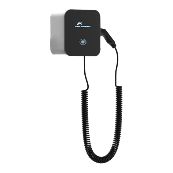
POWER ELECTRONICS NB Wall INTRODUCTION NB Wall is a robust and attractive outdoor AC Charging system, making it ideal for car parks and smart homes. Its smart design offers a simple, fast and easy charging experience, which makes NB Wall the best AC charging solution for applications that require maximum integration with the most advanced functionalities. - Page 16 NB Wall POWER ELECTRONICS The following image shows the charger overview with the main components: Status indicator RFID reader Charging connector Charging hose Note: The representation and location of the components may vary depending on the model. Connectors The characteristics and parts of each type of connector are indicated below. The appearance of the connectors may change to that shown in the following images.
-
Page 17: Charging Process
POWER ELECTRONICS NB Wall Charging process The following sequence presents the process to be followed by the user for use in a loading session: 1. If the user management has not yet been configured and the charger is available, connect the hose to the vehicle to start charging automatically and go to point 4. -
Page 18: Descriptive Label
NB Wall POWER ELECTRONICS Dual power sharing Thanks to the Dual Power Sharing functionality, the power is equally distributed between both outputs (or configurable) without exceeding the current limit set for the charger. When one of them finishes charging, the total power is available for the other one. -
Page 19: Technical Characteristics
POWER ELECTRONICS NB Wall TECHNICAL CHARACTERISTICS The NB Wall charger offers the following IEC standard features. For other configurations, consult Power Electronics. TECHNICAL CHARACTERISTICS... - Page 20 NB Wall POWER ELECTRONICS The NB Wall charger offers the following standard features for general US configurations for other configurations, consult Power Electronics. TECHNICAL CHARACTERISTICS...
-
Page 21: Dimensions And Weight
POWER ELECTRONICS NB Wall DIMENSIONS AND WEIGHT The dimensions and weight of the assembly that makes up each frame of the Power Electronics NB Wall charger is detailed in this section. Frame 1 GENERAL DIMENSIONS [mm] SPECIFIC DIMENSIONS [mm] HEIGHT (H) - Page 22 NB Wall POWER ELECTRONICS Frame 2 GENERAL DIMENSIONS [mm] SPECIFIC DIMENSIONS [mm] HEIGHT (H) WIDTH (W) DEPTH (D) EXTRA WIDTH (W’) 374,9 CENTER OF GRAVITY [mm] WEIGHT [kg] Frame 2 106,6 93,4 10,8 Note: the weight indicated is without hose and its connector.
-
Page 23: Handling And Transportation
The equipment is delivered perfectly packed and checked. Upon receipt, inspect the equipment. In the event of damage to the equipment, notify the logistics agent and Power Electronics 902 40 20 70, (International +34 96 136 65 57), or your nearest agent within 24 hours of receipt. Verify that the goods received correspond to the delivery note, models and serial numbers. -
Page 24: Handling And Transportation
NB Wall POWER ELECTRONICS Handling and transportation Only the transport methods described in this document are permitted. Follow the transportation requirements described here. Any other method of transport or handling may damage the unit or void the warranty. Charging posts are prepared for truck transport and manual handling. No extra tools are required for individual downloading. -
Page 25: Preparation For Installing The Equipment
POWER ELECTRONICS NB Wall PREPARATION FOR INSTALLING THE EQUIPMENT Site recommendations When deciding the location of the equipment and planning its installation, it is recommended to follow a series of guidelines derived from its characteristics. CAUTION To guarantee proper electrical installation, it is very important to comply with the bend radius of the cable. -
Page 26: Minimum Safety Distances
NB Wall POWER ELECTRONICS Minimum safety distances CAUTION When installing the equipment, keep the minimum safety distances and ensure proper conditions for maintenance tasks. Be aware of all the minimum insulation requirements established by the applicable electrical code, as well as the thermal, safety and accessibility requirements. The safety distances given in this section must not replace in any way the mandatory regulations of the country in which the equipment will be installed. -
Page 27: Anchoring Of The Equipment
POWER ELECTRONICS NB Wall The following figure shows examples of the cable range area for the standard IEC hose in a parking lot with the charger centralized: Anchoring of the equipment To anchor the charger, the user must use A2-70 stainless screws: two M5x50 for the braket and two M5x45 with neoprene washer for the equipment, all them with expansion plugs;... - Page 28 NB Wall POWER ELECTRONICS • Then, fix the bracket to the wall, with the flap where the holes are located at the bottom and in contact with the wall, and the grip flap being at the top separated from the wall. Check that it is correctly leveled.
-
Page 29: Ventilation System
POWER ELECTRONICS NB Wall Frame 2: NOTICE The access of the cables through the back of the charger must be taken into account before anchoring. “Cable access and Check the location and space required for subsequent entry in the connections”... -
Page 30: Charging Current Adjustment
NB Wall POWER ELECTRONICS Charging current adjustment NB Wall has a selector to limit the maximum charging current to the corresponding current available in the installation. This section indicates its location and adjustment. On the following image, the selector on the control card is highlighted:... -
Page 31: Cable Access And Connections
Refer to the recommended tightening torque for mechanical and electrical connections in the " TORQUE AND SCREW SIZING" section. Power Electronics is not responsible for damages resulting from an incorrect connection. Input wiring NOTICE The dimensioning of the input power cable of the charging point must be checked by a qualified electrician. -
Page 32: Access
NB Wall POWER ELECTRONICS Access The cables access the interior of the charger through a specific area designed for it, indicated in the following points depending on the frame of each equipment. Frame 1 In frame 1, the equipment has just one wiring entry and it is located at the bottom of the unit. The... - Page 33 POWER ELECTRONICS NB Wall Frame 2 In frame 2, the equipment has a wiring entry located at the bottom of the unit as shown below: BOTTOM CABLE ACCESS DIMENSIONS - FRAME 2 [mm] 61,9 36,3 37,9 98,9 112,3 131,9 46,3...
- Page 34 NB Wall POWER ELECTRONICS Cable entry plate The different holes are prepared for cable access, both for power supply and communications cables. The arrangement of the cables is showed below for each frame. Frame 1: The AC input connection enters the equipment through one of the holes on the right, highlighted in the image with a rectangle;...
-
Page 35: Connections
POWER ELECTRONICS NB Wall Connections AC power supply and ground The following images indicated how and where to make the connections of AC input and ground, it depends on the frame and protections included in each equipment. NOTICE Use only the points indicated for the cable connections with suitable ferrules for each connection. - Page 36 NB Wall POWER ELECTRONICS Para US: being from left to right: L1 and L2. Frame1: L1 L2 Frame 2: L1 L2 L1 L2 In case of not including the optional MCB protection: For IEC: the power supply connection is made on the lower terminal of the differential protection (RCD), highlighted by a rectangle;...
- Page 37 POWER ELECTRONICS NB Wall Frame 2: L1 L2 L3 N L1 L2 L3 N For US: the power supply connection is made on the general terminals highlighted by a rectangle; from left to right: L1, L2, and Ground (G) on the right extreme.
- Page 38 NB Wall POWER ELECTRONICS The ground cable: Frame 1: is connected to any of the holes on the base plate, except for the US version without MCB, which will be connected to the terminal block. Frame 2: The ground cable, from both power supply hoses, is connected to either of the holes on the right-hand side of the splitter, except for the US version without MCB, which will be connected to the terminal block.
- Page 39 POWER ELECTRONICS NB Wall Ethernet cable connection WARNING Before opening any door, the equipment must be completely isolated, without any tension. Be sure to follow the insulation guidelines and all safety instructions indicated in the "Safety instructions" section. Please use all the indicated PPE. Otherwise, you may get an electric shock.
-
Page 40: Protections
NB Wall POWER ELECTRONICS PROTECTIONS The NB Wall EV charger may include different hardware protections depending on the model and options selected. This section describes the different protections. Overcurrent and short circuit protection The IEC chargers include a differential switch (RCD) in each line and whose characteristics are as... -
Page 41: Interface
RFID reader LED • Status indicator: Depending on the frame of the charger, this will be the Power Electronics logo or a LED indicator next to each charging hose. It shows the current status of each of the posts, using... -
Page 42: Communications
NB Wall POWER ELECTRONICS COMMUNICATIONS The NB Wall can be connected to the internet over the local network using an Ethernet cable or Wi-Fi connection. It is also possible to connect via 3G / 4G mobile network thanks to the possibility of SIM card integration. -
Page 43: 3G / 4G Communications
POWER ELECTRONICS NB Wall 3G / 4G communications To access the charging point through connections via 3G / 4G, a SIM card of this type must be inserted in the charger control card at the point indicated below. NOTICE Once the SIM has been inserted, then it is required to configure it, and finally reset the system. -
Page 44: Commissioning
POWER ELECTRONICS COMMISSIONING CAUTION Commissioning may only be carried out by personnel authorized by Power Electronics. Read these instructions and all safety recommendations carefully. Failure to do so could result in damage to the equipment and serious injury to personnel. - Page 45 POWER ELECTRONICS NB Wall Adjust the charging current using an internal selector on the device. Check “Charging current adjustment” section. Verify that the AC input voltage is compatible with the AC voltage range of the equipment. Verify the selectivity of the external protections to the equipment and control parameters.
-
Page 46: Safe Stop
NB Wall POWER ELECTRONICS SAFE STOP CAUTION The shutdown of the equipment must only be carried out by personnel qualified. Read these instructions and all safety recommendations carefully. Otherwise, the equipment could be damaged and seriously injured personnel. The instructions in this manual do not replace or replace local or national regulations. It is the user's responsibility to comply with all safety standards that apply at the installation site. -
Page 47: Maintenance
POWER ELECTRONICS NB Wall MAINTENANCE The NB Wall charger has been developed based on a revolutionary design concept that simplifies significantly the tasks and reduces preventive and corrective maintenance times. Nonetheless, there are some actions and revisions required. Status Before detailing the maintenance procedure, it is convenient to define 2 possible states to carry out the tasks of maintenance. -
Page 48: Checklist
NB Wall POWER ELECTRONICS Checklist The list of tasks detailed below should be carried out annually. The time of each task is an estimate. MAINTENANCE TIME GLOBAL OPERATION TIME 1h and 30min TIME POWER TEST (STATUS 1) (minutes) Environmental conditions – visual check Enclosure state –... -
Page 49: Power Test (Status 1)
POWER ELECTRONICS NB Wall Power Test (status 1) 1. Environmental conditions – visual check Verify that the equipment environment complies with the specifications. Verify that the humidity is adequate. 2. Enclosure state – visual check Check the enclosure is in good general state and no traces of corrosion or impacts are present. Check the posts anchoring. -
Page 50: Dead Test (Status 2)
NB Wall POWER ELECTRONICS Dead Test (status 2) 1. Internal cleaning Check that the equipment does not show signs of dust, moisture, oxidation or presence of animals. If dust is found in the control electronics, use a specific vacuum cleaner for electronic boards. Otherwise, the electronic components may be damaged. - Page 54 24H TECHNICAL ASSISTANCE 365 DAYS A YEAR FIND YOUR NEAREST DELEGATION POWER-ELECTRONICS.COM/CONTACT/...
Need help?
Do you have a question about the NB WALL Series and is the answer not in the manual?
Questions and answers