
Related Manuals for Tellabs 8860

Summary of Contents for Tellabs 8860
- Page 1 ® System Installation 76.8860IM31-A Tellabs 8860 Multi-service Switch Router ® Revision A Copyright © 2004 Tellabs. All rights reserved.
- Page 2 Canada. Copyright Statement This Tellabs manual is owned by Tellabs or its licensors and protected by U.S. and international copyright laws, conventions, and treaties. Your right to use this manual is subject to limitations and restrictions imposed by applicable licenses and copyright laws.
-
Page 3: Table Of Contents
4. Initialize the 8860 MSR ........ - Page 4 8860 MSR Rear Connector Panel ........
- Page 5 8860 MSR Physical Specifications ........A-2...
- Page 6 PN 76.8860IM31-A Tellabs 8860 Multi-service Switch Router System Installation Other PLMs........... . . A-10 10 GigE PLM .
- Page 7 The Tellabs 8860 Multi-service Switch Router System Installation provides instructions for safely unpacking, installing, powering- up, testing and servicing the Tellabs 8860 Multi-service Switch Router (MSR). After completing the procedures in this installation guide, you can start managing and configuring the 8860 MSR equipment with the Tellabs®...
- Page 8 ❑ Chapter 1—Installation Overview —Provides a quick glance of the task sequence typically required for installing a 8860 MSR after all components have been removed from the shipping crate, site preparation is completed, and all components have been inspected. ❑...
- Page 9 The warning symbol alerts you about action(s) or inaction(s) that could lead to personal injury or damage to the 8860 MSR equipment. ARNING The laser radiation symbol alerts you about actions that, if performed incorrectly, can result in exposure to hazardous invisible radiation.
- Page 10 The safety precautions listed in this section represent warnings associated with certain dangers of which Tellabs is aware. You, as the user of this product, must observe these warnings and all other safety precautions necessary to ensure your personal safety as well as the continued safe operation of the 8820 MSR in your operating environment.
- Page 11 2 AWG lug (Panduit LCD series), and two 5/16-18 UNC nuts are furnished with the chassis. To properly ground the 8860 MSR, use a 2 AWG copper grounding cable that is long enough to connect the nearest earth ground point at the site to the 8860 MSR chassis ground lug.
- Page 12 For centralized DC power connection install only in a restricted access area. AUTION Do Not Substitute Parts or Modify Equipment Do not install substitute parts or perform any unauthorized modification of the 8860 MSR system. Contact your local Tellabs representative for service and repair. Danger! Shock Hazard...
-
Page 13: Installation Overview
Installation Overview CHAPTER 1 This chapter introduces the task sequence typically required for installing a Tellabs® 8860 Multi-service Switch Router after all components have been removed from the shipping crate, site preparation is complete, and all components have been inspected. Installation overviews are provided in the following sections of this chapter: ❑... -
Page 14: Overall Installation Sequence
Power and Ground, on page 4-5 for details. 3. Position, Load, and Cable the 8860 MSR Prior to installing the 8860 MSR in a rack you may need to install the mounting brackets provided with the equipment as shown by the following steps: Step 1... -
Page 15: Initialize The 8860 Msr
PN 76.8860IM31-A Tellabs 8860 Multi-service Switch Router System Installation 4. Initialize the 8860 MSR This section provides guidelines for attaching the 8860 MSR to a network and performing an initialization sequence. Detailed information is provided in the following sections: ❑... - Page 16 System IP Address ❑ IP mask ❑ Gateway IP Address Connect a Local Console to the 8860 MSR, on page 4-24 Connect the local console (computer or terminal server) to the SCC serial port. Apply and Verify Power, on page 4-25 Power up and perform initial configuration of the system.
-
Page 17: Unpacking And Site Preparation
Unpacking and Site CHAPTER 2 Preparation This chapter describes the 8860 Multi-service Switch Router shipping contents and site preparation requirements, and provides guidelines for preparing the 8860 MSR for installation, in the following sections: ❑ Safety Information, on page 2-2 ❑... -
Page 18: Safety Information
8860 MSR. Unpacking the 8860 MSR The 8860 MSR arrives in at least two crates, one of which contains the 8860 MSR chassis, and other(s) that contain the Switch Control Card(s) (SCCs), Universal Line Card(s) (ULCs), and the Physical Line Modules (PLMs). -
Page 19: Uncrate And Inspect
8860 MSR cardboard carton. Step 3 Disassemble the cardboard carton. Remove the top lid and set it aside. You can now see the 8860 MSR accessory box surrounded by protective foam pads. Remove the accessory box and foam pads, and set them aside. -
Page 20: Accessory Box Inspection
Step 4 Use standard operating procedures (per your site safety guidelines) to carefully lift the 8860 MSR away from the shipping pallet, and place it on the ground or on a cart for transport to the installation site. Accessory Box Inspection... -
Page 21: Circuit Pack Crate Inspection And Disassembly
DC Power Terminal Block Hardware Stack-up Circuit Pack Crate Inspection and Disassembly When unpacking the 8860 MSR circuit packs, you will first disassemble the wood crate, then remove the individual cardboard carton and ESD wrap for each circuit pack as shown... -
Page 22: Verify Receipt
Tellabs, Inc. Postal Address 90 Rio Robles San Jose, CA 95134 Returning Products to Tellabs Use the procedure in this section to authorize return of defective product(s) to Tellabs. Step 1 (Table 2-2) Contact to request a Tellabs Advanced Data Products Technical Support Return Material Authorization (RMA) number. -
Page 23: Site Preparation
❑ DS3 Clear Channel and Channelized PLM Details, on page 2-14 Tools and Supplies Requirements This section lists the tools and supplies typically required to perform a 8860 MSR (Table 2-3) installation , which are not supplied in your shipping container. -
Page 24: Rack Requirements
Rack Requirements Mounting brackets are shipped pre-mounted on the 8860 MSR, in position for attachment to a standard 23-inch EIA relay rack. For information about modifying the bracket Adjusting Mounting Brackets, on page 4-3... -
Page 25: Environmental Requirements
Thermal Output 15,354 BTU/hr The 8860 MSR must be installed in a restricted access location, as defined in U.S. Articles 10-116, 10-117, and 10-118 of the National Electrical Code ANSI/NFPA 70, and as advised 8860 MSR Rear Connector Panel, on page 3-12... -
Page 26: Power Requirements
Tellabs 8860 Multi-service Switch Router System Installation Power Requirements Nominal voltage for the 8860 MSR is -48 VDC, with mandatory operating range from -40 VDC to -56.7 VDC. The -48V DC power distribution within the chassis is independent down to the unit level (circuit packs, fans, and system panel electronics). On-board power Table converter components generate the specific lower voltages required by the electronics. -
Page 27: Optical Network Plm Description And Cable Connection
PN 76.8860IM31-A Tellabs 8860 Multi-service Switch Router System Installation Optical Network PLM Description and Cable Connection Table 2-7 lists the PLM types, product codes, and PLM descriptions for the PLMs that requires optical network cables for the 8820 MSR installation. Be sure to obtain these cables before proceeding with your installation. - Page 28 PN 76.8860IM31-A Tellabs 8860 Multi-service Switch Router System Installation Table 2-7 PLM Optical Network Cables PLM Type PLM Product Code PLM Description Cable Type and Connector Per Port Single mode, LC 81.8800-PLM012-20 OC-12/STM-4 MS SMF IR connector Single mode, LC OC-12 81.8800-PLM012-30...
-
Page 29: Fast Ethernet Plm Details
PN 76.8860IM31-A Tellabs 8860 Multi-service Switch Router System Installation Fast Ethernet PLM Details Table 2-8 contains the Fast Ethernet PLM product code, description, cable type and Table 2-9 connector per port needed for an 8820 MSR installation. lists the spares and accessories that can be obtained for the Fast Ethernet PLM. -
Page 30: Ds3 Clear Channel And Channelized Plm Details
PN 76.8860IM31-A Tellabs 8860 Multi-service Switch Router System Installation DS3 Clear Channel and Channelized PLM Details Table 2-10 contains the DS3 clear channel and channelized PLM details for an 8820 MSR Table 2-11 installation. lists the spares and accessories that can be obtained for the DS3 PLM. -
Page 31: Equipment Overview
Equipment Overview CHAPTER 3 This chapter describes the 8860 MSR hardware components, in the following sections: ❑ 8860 MSR Chassis, on page 3-2 ❑ 8860 MSR Rear Connector Panel, on page 3-12 ❑ Switch and Control Card, on page 3-15 ❑... -
Page 32: 8860 Msr Chassis
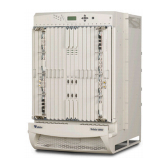
PN 76.8860IM31-A Tellabs 8860 Multi-service Switch Router System Installation 8860 MSR Chassis (Figure 3-2) The 8860 MSR chassis consists of the components described in the following sections: ❑ Card Cage, on page 3-3 ❑ System Panel, on page 3-3 ❑... -
Page 33: Card Cage
Tellabs 8860 Multi-service Switch Router System Installation Card Cage The 8860 MSR card cage provides 19 full-height, vertical slots into which the 8860 MSR Switch and Control Cards (SCC), Universal Line Cards (ULCs), and card blank panels may be installed. -
Page 34: Environmental Status Leds
PN 76.8860IM31-A Tellabs 8860 Multi-service Switch Router System Installation Environmental Status LEDs The system panel environmental LEDs are labelled Temp, Fan, and Pwr1, Pwr2, and Pwr3. Table 3-1 Environmental alarm severity is reported by means of the colors described in... -
Page 35: Alarm Leds
PN 76.8860IM31-A Tellabs 8860 Multi-service Switch Router System Installation Alarm LEDs The system panel alarm LEDs are labelled CRT, MAJ, and MIN. System alarm severity is Table 3-2 reported by means of the colors described in Table 3-2 Alarm LED Descriptions... -
Page 36: Aco Button
PN 76.8860IM31-A Tellabs 8860 Multi-service Switch Router System Installation For instance, to display information about Switch Card 1 (SCC1) from the craft display Figure 3-4 panel use the sequence shown in . Press the Enter button to move from panel to panel, as shown by the illustration. - Page 37 PN 76.8860IM31-A Tellabs 8860 Multi-service Switch Router System Installation Alarm Silencing Figure 3-3 To silence an alarm, quickly depress the ACO button. (See for the location of this button.) 8860 MSR Chassis System Panel Equipment Overview...
-
Page 38: Card Status Leds
PN 76.8860IM31-A Tellabs 8860 Multi-service Switch Router System Installation Card Status LEDs A card status LED is located on the chassis—above each ULC and SCC slot—to indicate the overall status of the installed card. Status LEDs are also provided on the ULCs, SCCs, and... -
Page 39: Fan Tray Assembly
16 fans that provide airflow and heat dissipation for the system. This unit is serviceable onsite, and network services are not interrupted when the fan tray is removed for servicing. The 8860 MSR provides fan redundancy such that if a single fan fails, the remaining fans continue to cool the chassis. ❑... -
Page 40: Air Filter
Tellabs 8860 Multi-service Switch Router System Installation Air Filter The 8860 MSR air filter assembly fits between the fan tray assembly and the card cage, to allow cooling air into the chassis and minimize internal contamination. The air filter must be maintained to ensure that air continues to flow into the chassis. -
Page 41: Cable Management
— organizes and routes cables to and from the 8860 MSR shelf. Cable guides are positioned vertically along the lengths of the installed cards. The cable tray is part of the chassis assembly, located beneath the card slots. -
Page 42: 8860 Msr Rear Connector Panel
PN 76.8860IM31-A Tellabs 8860 Multi-service Switch Router System Installation 8860 MSR Rear Connector Panel (Figure 3-7) The rear connector panel contains the components described in the following sections: ❑ Intershelf Cabling Connectors, on page 3-13 ❑ Serial Connector, on page 3-13 ❑... -
Page 43: Intershelf Cabling Connectors
The back-panel SERIAL connector is a DB-9 male, RS-232 port, which is referred to as the aux port in the Tellabs® Multi-service Operating System. You can use this serial port for logging in at the 8860 MSR and/or performing diagnostics and debugging activities. -
Page 44: T1 Bits External Timing Connectors
T1 BITS signals to other devices that may require BITS timing. DC Power Blocks The 8860 MSR chassis contains three DC power blocks that must be wired to the installation site. Each power block is equipped with primary (A) and redundant (B) power and group lugs, and is responsible for powering a specific set of slots on the chassis. -
Page 45: Switch And Control Card
The switch and control cards (SCCs) provide the switch fabric, timing, routing and management functions for the 8860 MSR. Up to three SCCs may be installed in the 8860 MSR, at slots labelled S1, S2, and S3 (located at the center of the card cage between line- card slots labelled 8 and 9). - Page 46 PN 76.8860IM31-A Tellabs 8860 Multi-service Switch Router System Installation LED column associated with status of the MP LED management processor. column MP LED column LED column associated with status of the RP LED column RP LED routing processor. column Active LEDs...
-
Page 47: Using The Shutdown Button On The Scc
SCC from the shelf. The 8860 system will switch over to the standby card if this button is pressed on the active SCC card. -
Page 48: Universal Line Cards
PN 76.8860IM31-A Tellabs 8860 Multi-service Switch Router System Installation Universal Line Cards (Figure 3-9) he universal line card (ULC) handles all packet management, processing, and scheduling. ULCs are installed in slots 1 through 8 and/or slots 9 through 16. ULC can... - Page 49 PN 76.8860IM31-A Tellabs 8860 Multi-service Switch Router System Installation Figure 3-10 ULC with Populated PLM slots 3-19 Universal Line Cards Using the Shutdown Button on the SCC Equipment Overview...
-
Page 50: Physical Line Modules
The line card can detect the presence of a PLM and the type of PLM in each of the four module interface positions. Optical PLMs The 8860 MSR PLMs are available in numerous configurations, as described in and Power Requirements, on page A-5 Blank Panels All unpopulated chassis and ULC slots must be covered by blank panels. -
Page 51: Installation
Connect T1 BITS Clocks, on page 4-22 ❑ Connect 8860 MSR Alarm Outputs, on page 4-23 ❑ Connect a Local Console to the 8860 MSR, on page 4-24 ❑ Apply and Verify Power, on page 4-25 ❑ Let the System Boot Up, on page 4-26 ❑... -
Page 52: Rack-Mount The 8860 Msr
(ESD) when working with system components, wear the wrist ESD W ARNING grounding strap and attach it to the ESD jack on the 8860 MSR system panel. Do not apply power to the 8860 MSR until you complete all installation tasks in this chapter. -
Page 53: Adjusting Mounting Brackets
Tellabs 8860 Multi-service Switch Router System Installation Adjusting Mounting Brackets The 8860 MSR ships with mounting brackets already attached and in position for attachment to a standard 23-inch EIA relay rack. You can adjust the brackets to accommodate a cabinet mount by reorienting the mounting flange to face front, and attaching an optional cabinet mount bracket kit (Part Number 20- 1098-000) on the rear of the 8860 MSR for support. -
Page 54: Positioning And Securing 8860 Msr
(Figure 4-2) With two people at opposite sides of the chassis, lift the chassis insert the 8860 MSR through the front of the rack. A third person should be in position to support the rear of the chassis during the lift. -
Page 55: Connect Power And Ground
PN 76.8860IM31-A Tellabs 8860 Multi-service Switch Router System Installation Connect Power and Ground This section describes how to configure DC power for the 8860 MSR, in the following topics: ❑ Overview, on page 4-5 ❑ Ground the 8860 MSR Chassis, on page 4-7 Table 2-4 on page 2-8 for all DC power feed installation supplies. - Page 56 A dedicated, appropriately rated DC power source is required for each connection. ❑ The DC power cables must be terminated by dual-hole cable lugs at the 8860 MSR end. Tools and The lugs must fit over M6 terminal studs on .625-in (15.88mm) centers. See Supplies Requirements, on page 2-8 for proper nut driver/torque driver specifications.
-
Page 57: Ground The 8860 Msr Chassis
Figure 4-4 Dual-post-lug Grounding Connector Tri-Power Grounding and Connection Use guidelines in this section to establish the power and ground connections to each 8860 MSR DC power block. Observe proper polarity when making these connections. Do not reverse the –48V and ground connections on any block. - Page 58 Step 3 Reinstall the protector covers on all three DC power blocks. Do not apply power to the 8860 MSR chassis at this time. Proceed to the next section and begin loading the chassis with cards and modules. After you finish installing the cards and connecting the chassis to external...
-
Page 59: Load The Chassis
PN 76.8860IM31-A Tellabs 8860 Multi-service Switch Router System Installation Load the Chassis This section provide procedures for plugging SCCs, ULCs, PLMs, and blank panels into the 8860 MSR shelf, in the following sections: ❑ Install the Switch and Control Cards, on page 4-10 ❑... -
Page 60: Scc And Ulc Installation Sequence
S1 or S3. An SCC in slot S1 requires an installed ULC in slot 8. If an SCC is installed in slot S3, a ULC must also be installed in slot 9. SCC Slot Rules Use the following guidelines to load up to three SCCs into the 8860 MSR chassis slots labeled S1-S3: ❑... -
Page 61: Loading Sccs
PN 76.8860IM31-A Tellabs 8860 Multi-service Switch Router System Installation ❑ For maximum-SCC configuration, install the third SCC into slot S2. Use this slot only if slots S1 and S3 contain SCCs. The card state of this SCC will be reported by the live system as S2 if the SCC is administratively enabled. - Page 62 PN 76.8860IM31-A Tellabs 8860 Multi-service Switch Router System Installation Push the ejector bar to enable the first ejector teeth to slide under the ejector bar, and the second ejector teeth contact the bar, and push in on the ejector bar...
-
Page 63: Install The Universal Line Cards
PN 76.8860IM31-A Tellabs 8860 Multi-service Switch Router System Installation Install the Universal Line Cards The ULCs can be inserted into slots 1 through 8 (chassis left side) and 9 through 16 (chassis right side). ULC Slot Rules You must use slots 8 and 9 to install ULCs prior to installing ULCs in any other slot. - Page 64 PN 76.8860IM31-A Tellabs 8860 Multi-service Switch Router System Installation You will need to apply significant force on the ULC ejec- tors to secure and close the ejector levers. (Figure Before installing a ULC with pre-installed PLMs 4-8) , secure the PLMs to the ULC by tightening the panel screws on the PLM faceplates.
- Page 65 PN 76.8860IM31-A Tellabs 8860 Multi-service Switch Router System Installation Figure 4-10 Securing the Ejector Lever Removing the bezel in front of the cable management tray will make securing the lower ejector screws easier. 4-15 Load the Chassis Install the Universal Line Cards...
-
Page 66: Install An Oc-192C/Stm-64C Plm
PN 76.8860IM31-A Tellabs 8860 Multi-service Switch Router System Installation Install an OC-192c/STM-64c PLM (Figure 4-11) The OC-192c/STM-64c PLM , which occupies a single card slot, can be inserted into slots 1 through 8 or slots 9 through 16. The procedure for installing this module is identical to that described for installing ULCs... -
Page 67: Install A 10 Gigabit Ethernet Plm
PN 76.8860IM31-A Tellabs 8860 Multi-service Switch Router System Installation Install a 10 Gigabit Ethernet PLM (Figure 4-11) The 10 Gigabit Ethernet PLM , which occupies a single card slot, can be inserted into slots 1 through 7 or slots 10 through 16. The procedure for installing this PLM is... -
Page 68: Install Blank Panels
PN 76.8860IM31-A Tellabs 8860 Multi-service Switch Router System Installation Step 3 Tighten the thumb screws at the top and bottom of the PLM, gently and fully. Install Blank Panels This section describes how to install card-slot blank panels and PLM blank panels, in the following topics: ❑... - Page 69 PN 76.8860IM31-A Tellabs 8860 Multi-service Switch Router System Installation Step 1 Insert the blank panel into one of the card slots. Step 2 After the first ejector tooth slides under the ejector bar, and the second contacts the bar, push in on the ejector to seat the card to the backplane.
-
Page 70: Install Plm Blank Panels Into Ulcs
PN 76.8860IM31-A Tellabs 8860 Multi-service Switch Router System Installation Install PLM Blank Panels into ULCs Blank card-slot panels are provided with the 8860 MSR ULCs. All unused PLM slots on a (Figure 4-14) ULC must be covered with these panels Step 1 Insert the PLM blank panel into the empty PLM module slot. -
Page 71: Connect Plms To The Optical Network
Figure 4-15 Use guidelines shown in to attach cable to the optical port of the PLM, and to guide the cable through the 8860 MSR cable management scheme. . Plug each cable into the PLM’s port connector. . Retract the latch on the side of each cable guide. -
Page 72: Connect T1 Bits Clocks
You can also connect one or two T1 BITS (building integrated timing supply) signals to the 8860 MSR for external timing. Each signal must use either SF or ESF framing. You can also send these input signals from the 8860 MSR to other local devices that may require BITS timing. -
Page 73: Connect 8860 Msr Alarm Outputs
For each type of alarm, connect the common leads and either the normally open (N.O.) or normally closed (N.C.) leads to the alarm annunciator or other external alarm system. Whenever the 8860 MSR declares an alarm, that system will provide visual and audible indications to alert office craftspersons of that condition. -
Page 74: Connect A Local Console To The 8860 Msr
Tellabs 8860 Multi-service Switch Router System Installation Connect a Local Console to the 8860 MSR The 8820 MSR console port provides access to the Tellabs® Multi-service Operating System (OS), which is the command line interface (CLI). Use the modular, null-modem (crossover) -
Page 75: Apply And Verify Power
PN 76.8860IM31-A Tellabs 8860 Multi-service Switch Router System Installation Apply and Verify Power Use the following procedure to apply power to the 8860 MSR: Step 1 Verify that all -48V power and ground connections are correctly established: make sure that polarity is not reversed on any pair of connections on any DC power blocks. -
Page 76: Let The System Boot Up
Tellabs 8860 Multi-service Switch Router System Installation Let the System Boot Up The console screen now displays boot up script from the 8860 MSR switch. You can monitor the system display at the console to ensure that the system boot process completes all three stages. -
Page 77: Log Into The 8860 Msr Console Interface
To see more information about how to use CLI for site practices, refer to the Tellabs Multi-service Operating System User Guide. If you need to log out To log out of the 8860 MSR at the console, type the logout command at the CLI prompt: logout 8860#... -
Page 78: Change The Default Password
PN 76.8860IM31-A Tellabs 8860 Multi-service Switch Router System Installation Change the Default Password When the 8860 MSR switch is first powered up it provides two default logins at the CLI for (Table 4-2) two user types—root and admin Table 4-2... -
Page 79: Set A Static Route
8820# enable config protocol ip route 24.0.1.0/24 24.0.1.1 Connect the Ethernet Management Port Your 8860 MSR shipment includes an Ethernet RJ-45 cable for use to connect to your management IP network. Use the cable to connect the 8860 MSR MGMT port to that network. -
Page 80: Connect To The Ip Management Network
❑ Network Subnet Mask ❑ Gateway Address To assign the network parameters for the 8860 MSR, use the following steps: Step 1 Log into the console interface and bring up the CLI. Step 2 Assign the IP address and network subnet mask by entering the management IP configuration command, similar to the following example: 8860# enable config system mgmt-ip ip-address 10.20.0.13/24... -
Page 81: 8860 Msr Specifications
8860 MSR. ❑ 8860 MSR Physical Specifications, on page A-2 ❑ 8860 MSR System Management and Alarm Specifications, on page A-3 ❑ 8860 MSR System Power Requirements, on page A-4 ❑ Optical PLMs and Power Requirements, on page A-5 ❑... -
Page 82: 8860 Msr Physical Specifications
PN 76.8860IM31-A Tellabs 8860 Multi-service Switch Router System Installation 8860 MSR Physical Specifications Table A-1 Physical Specifications Characteristic Detail ❑ Height 35.0 in (88.90 cm) ❑ Width 21.625 in (54.9 cm) ❑ Depth 29.50 in (74.93 cm) ❑ Weight (fully loaded chassis) 385 lb (780 Kg) ❑... -
Page 83: 8860 Msr System Management And Alarm Specifications
PN 76.8860IM31-A Tellabs 8860 Multi-service Switch Router System Installation 8860 MSR System Management and Alarm Specifications ❑ Two RS-232 (DB-9 connector) serial ports for remote and console connections ❑ 10/100 Mb/s Ethernet (RJ-45) port for out-of-band management ❑ Premise Alarm (DB-25) connector ❑... -
Page 84: 8860 Msr System Power Requirements
PN 76.8860IM31-A Tellabs 8860 Multi-service Switch Router System Installation 8860 MSR System Power Requirements Table A-2 Power Requirements Characteristic Detail ❑ Power arrangement Three, redundant inputs: Input 1, Input 2, and Input 3 ❑ Maximum power 4500 Watts ❑ Max current (per input) 60A at -40VDC ❑... -
Page 85: Optical Plms And Power Requirements
PN 76.8860IM31-A Tellabs 8860 Multi-service Switch Router System Installation Optical PLMs and Power Requirements The following sections provide the optical power requirement specifications for all SONET/SDH PLMs. ❑ OC-3 PLMs, on page A-6 ❑ OC-12 PLMs, on page A-7 ❑... -
Page 86: Oc-3 Plms
PN 76.8860IM31-A Tellabs 8860 Multi-service Switch Router System Installation OC-3 PLMs (Figure A-1) The OC-3/STM-1 PLM is a four-port STS-3/STM-1 module that can be plugged into any of the four slots on a ULC. Faceplate Detail ❑ Four independent 155.52 Mbps SONET/SDH STS-3/... - Page 87 PN 76.8860IM31-A Tellabs 8860 Multi-service Switch Router System Installation OC-12 PLMs (Figure A-2) The OC-12/STM-4 PLM is a four-port STS-12/STM-4 module that can be plugged into one of the four slots on a ULC. Faceplate Detail ❑ Four independent 622.08 Mbps SONET/SDH STS-12/...
-
Page 88: Oc-48 Plms
PN 76.8860IM31-A Tellabs 8860 Multi-service Switch Router System Installation OC-48 PLMs (Figure A-3) The OC-48/STM-16 PLM is a single-port STS-48/STM-16 module that can be plugged into any of the four slots on the ULC. Faceplate Detail ❑ Four independent 2.488Gbps SONET/SDH STS-48/STM-... - Page 89 PN 76.8860IM31-A Tellabs 8860 Multi-service Switch Router System Installation OC-192 PLMs (Figure A-4) The OC-192C/STM-64C PLM is a full-height, single-port STS-192c/STM-64c modules, which occupies a full ULC slot. Faceplate Detail ❑ Concatenated 9.952 Gbps (STS-192c/STM-64c) over single fiber mode to carry packet-over-SONET (POS), Frame Relay, and Point-to-point (PPP) payloads ❑...
-
Page 90: Other Plms
PN 76.8860IM31-A Tellabs 8860 Multi-service Switch Router System Installation Other PLMs The following sections provide faceplate descriptions and power requirements for Ethernet PLMS. ❑ 10 GigE PLM, on page A-11 ❑ GigE PLM, on page A-12 ❑ Fast Ethernet PLM, on page A-13 ❑... -
Page 91: 10 Gige Plm
PN 76.8860IM31-A Tellabs 8860 Multi-service Switch Router System Installation 10 GigE PLM (Figure A-6) The 10 GigE PLM is a full-card-height, 10 Gigabit Ethernet module. Faceplate Detail ❑ Single 10 Gigabit Ethernet over fiber, LAN-PHY (10 Km) and WAN-PHY (10 Km) SC connector ❑... - Page 92 PN 76.8860IM31-A Tellabs 8860 Multi-service Switch Router System Installation GigE PLM (Figure A-6) Each Gigabit Ethernet (GigE) PLM is a four-port Gigabit Ethernet module that can be plugged into any of the four slots of a ULC. Faceplate Detail ❑...
-
Page 93: Fast Ethernet Plm
PN 76.8860IM31-A Tellabs 8860 Multi-service Switch Router System Installation Fast Ethernet PLM (Figure A-6) Each Fast Ethernet PLM is a 24-port fast Ethernet module that can be plugged into any of the four slots of a 8820 MSR. Faceplate Detail ❑... -
Page 94: Ds3/E3 Clear Channel Plm
6 port T3/E3 for the Tellabs 8800-series Multi- service Switch Routers. A DS3 PLM may be used in any open PLM slot on any Tellabs 8800-series MSR. The DS3 PLM supports 6 ports of T3 or E3 by using six pairs of SMB connectors. -
Page 95: Ds3 Channelized Plm
Each DS3 channelized PLM is a 6 port T3/E3 for Tellabs 8800-series Multi- service Switch Routers. A DS3 PLM may be used in any open PLM slot on any Tellabs 8800-series MSR. The DS3 channelized PLM supports 6 ports of channelized DS3 with support for any valid combinations of nxDS1 or nxDS0 by using six pairs of SMB connectors. -
Page 96: Environmental Requirements
PN 76.8860IM31-A Tellabs 8860 Multi-service Switch Router System Installation Environmental Requirements Table A-9 Environmental Requirements Characteristic Detail ❑ Operating temperature 0°C (32°F) to 45°C (113°F) ❑ Operating humidity 5% to 90% non-condensing ❑ Storage and transit temperature –40°C (–40°F) to +70°C (158°F) ❑... -
Page 97: Safety And Compliance Specifications
PN 76.8860IM31-A Tellabs 8860 Multi-service Switch Router System Installation Safety and Compliance Specifications Table A-10 Safety and Compliance Specifications Characteristic Detail ❑ EN60825-1/2 Safety ❑ AS/NZS 3260 ❑ UL 1950, 3rd Edition ❑ EN60950 ❑ CSA C22.2 No 950 ❑... -
Page 98: Connector And Adapter Pinouts
PN 76.8860IM31-A Tellabs 8860 Multi-service Switch Router System Installation Connector and Adapter Pinouts This section provides connector and associated adapter detail in the following topics: ❑ Console Serial Connector ❑ RJ45-to-DB9 Connector Adapters ❑ Ethernet (IP Management) Connector ❑ External Alarm Connector ❑... -
Page 99: Console Serial Connector
PN 76.8860IM31-A Tellabs 8860 Multi-service Switch Router System Installation Console Serial Connector The SERIAL connector of the switch and control card (SCC) provides the pinouts shown in Table A-11 . This connector is for a connection to a local VivOS CLI terminal. -
Page 100: Rj45-To-Db9 Connector Adapters
RJ45-to-DB9 Connector Adapters Table A-12 lists the pin-to-pin cross-connections of the two RJ-45 female-to-DB-9 female connector adapters furnished with the 8860 MSR. Use these adapters when connecting a local console to the SERIAL jack of the system’s primary SCC. Table A-12... -
Page 101: Ethernet (Ip Management) Connector
PN 76.8860IM31-A Tellabs 8860 Multi-service Switch Router System Installation Ethernet (IP Management) Connector The IP Management (MGMT) connector on the chassis rear connector panel is an RJ-45 10/ Table A-13 100 Ethernet connector with pinouts shown in Table A-13 Management Connector Pinouts... -
Page 102: External Alarm Connector
PN 76.8860IM31-A Tellabs 8860 Multi-service Switch Router System Installation External Alarm Connector The DB-25 connector supports three visual alarms, three audible alarms, and an external Table A-14 ACO input. Pinouts for the external alarm interface are shown in Table A-14... -
Page 103: External Bits Timing Connectors
PN 76.8860IM31-A Tellabs 8860 Multi-service Switch Router System Installation External BITS Timing Connectors Table A-15 The four DB-15 external timing connectors use the pinouts shown in . The two top connectors (BITS IN A and B) are for the two incoming BITS clock signals, and the two bottom connectors (R BITS OUT A and B) pass the recovered clock to external devices. -
Page 104: Port Densities
PN 76.8860IM31-A Tellabs 8860 Multi-service Switch Router System Installation Port Densities Table A-16 lists the port densities for the 8860 MSR PLMs. Table A-16 PLM Port Densities Per 8860 Physical Interfaces Per PLM Per 7-ft Rack OC-192c/STM-64c OC-48/STM-16 OC-48c/STM-16c OC-12/STM-4... -
Page 105: Setting Boot Parameters
APPENDIX B Parameters The Multi-service Operating System is pre-installed and ready for system configuration after powering up the 8860 Multi- service Switch Router. During system bootup, check to ensure that the hardware LEDs are reporting proper status. The client IP address, IP mask, and IP gateway address must exactly match those configured on the IP management port. -
Page 106: Viewing And Modifying Boot Parameters
Tellabs 8860 Multi-service Switch Router System Installation Viewing and Modifying Boot Parameters During an initial boot up, the console screen displays the boot up script from the 8860 MSR. Use the following steps to view and modify the boot parameters: Step 1 Press the ESC key to interrupt the boot script, and to present the M prompt. - Page 107 PN 76.8860IM31-A Tellabs 8860 Multi-service Switch Router System Installation M>dc Node address Client IP address ......: 10.8.4.63 Gateway used by the management Network IP mask ......: 255.255.0.0 Ethernet interface for connection to any Gateway IP address ......: 10.8.0.1 external non-directly connected manage- TFTP server IP address .......
- Page 108 PN 76.8860IM31-A Tellabs 8860 Multi-service Switch Router System Installation Step 5 Use the boot command to restart the normal booting sequence, and wait for the CLI banner to display. M>boot Vivace Networks First Stage Boot Loader Version 1.2.0 Copyright (c) 1999-2002 Vivace Networks, Inc.
- Page 109 PN 76.8860IM31-A Tellabs 8860 Multi-service Switch Router System Installation Mounting disks ... Disk operations completed. Starting boot services ... Boot services started. Initializing multiboard operations ... Multiboard operations completed. Enabling shelf services ... Shelf services enabled. Validating software version .. Pass through for switch card.
- Page 110 PN 76.8860IM31-A Tellabs 8860 Multi-service Switch Router System Installation Login: root Default user name login: root Default password: viva-private Password: |----------------------------------------------------------------------------------------------| | CHANGE ALL DEFAULT PASSWORDS IN 5 MINUTES, OTHERWISE | YOUR SESSION WILL BE TERMINATED |----------------------------------------------------------------------------------------------| Change password for: root...
- Page 111 ESD grounding strap 2-2 COM port configuration 4-24 CPX-1000 FAN LED 3-4, 3-9 installation requirements 2-1, 3-1, 4- Fast Ethernet PLM cable details 2-13, 2-14 mounting to equipment rack 4-4 safety precautions 2-x Tellabs 8860 Multi-service Switch Router System Installation INDEX-1...
- Page 112 PN 76.8860IM31-A Tellabs 8860 Multi-service Switch Router System Installation faceplate and power product code and cable requirements A-13 requirements 2-12 faceplate details A-13 OC-3c PLM port density A-24 product code and cable fatality precautions 2-x, 2-xii requirements 2-12 fuses 2-10...
- Page 113 PN 76.8860IM31-A Tellabs 8860 Multi-service Switch Router System Installation User login 4-28 INDEX-3...
Need help?
Do you have a question about the 8860 and is the answer not in the manual?
Questions and answers