
Summary of Contents for SIGRIST VisGuard 2
- Page 1 Document number: 14162E Version: 2 Valid from: S/N 704010/ SW V529 INSTRUCTION MANUAL VisGuard 2 Visibility Monitor / Dust Monitor...
- Page 2 Copyright© SIGRIST-PHOTOMETER AG, subject to technical changes without notice 4/2018 SIGRIST-PHOTOMETER AG Tel. +41 41 624 54 54 Hofurlistrasse 1 +41 41 624 54 55 CH-6373 Ennetbürgen inf o@photome ter. com Switzerland w w w .photome ter.com...
-
Page 3: Table Of Contents
Mounting the optional junction box............28 Mounting the SIPORT 2 connection box ............. 28 Mounting the SIPORT 2 without housing ............ 28 Installing the 230 VAC sample heater on the VisGuard 2 ......29 Mounting the SICON (M) ................30 Electrical installation .................... 31 Safety pointers for the electrical connection.......... - Page 4 Instruction Manual VisGuard 2 Contents 5.2.9 Connecting a pressure monitor on extractive systems......40 5.2.10 Connecting the optional junction box ........... 41 Connecting the SICON (M) ............... 43 5.3.1 Removing the cover from the SICON (M) ..........43 5.3.2 Overview of the opened SICON (M) control unit ........44 5.3.3...
- Page 5 Cleaning the outside of the VisGuard 2 ............83 Cleaning the sample inlet ................. 84 Replacing the filter cartridge in the VisGuard 2 In-situ ........85 Replacing the fan on the VisGuard 2 In-situ ..........87 Recalibrating the VisGuard 2 ..............89 9.6.1...
- Page 6 Instruction Manual VisGuard 2 Contents Thi s page i s i n t e nt i o nal l y bl a nk M akr o 14162E/2...
-
Page 7: General User Information
Purpose of the Instruction Manual This Instruction Manual provides the user with helpful information about the entire life cycle of the VisGuard 2 and its peripheral devices. Before commissioning the ins trument, you should be completely familiar with the Instruction Manual. -
Page 8: Order Document
The most recent version of this document can be downloaded at www.photometer.com (first time registration required). It can also be ordered from a SIGRIST representative in your country ( Instruction Manual “Customer service information”). Proper use The photometer and its peripherals are designed for measuring visibility and dust in non- explosive atmospheres at ambient temperatures of between -30 °C (minimum) and 55 °C... -
Page 9: Dangers When Not Used Properly
The instrument is not installed and operated in accordance with the Instruction Manual. The instrument has been operated with accessory parts which SIGRIST -PHOTOMETER AG has not expressly recommended. Improper changes to the instrument have been performed. -
Page 10: Meaning Of The Pictograms
1.14 Meaning of the pictograms All pictograms used in this document are explained below: Additional information about the current topic. Practical procedures when working with the VisGuard 2. Manipulations on the touchscreen. The screenshot is an example and may differ from current device. -
Page 11: Instrument Overview
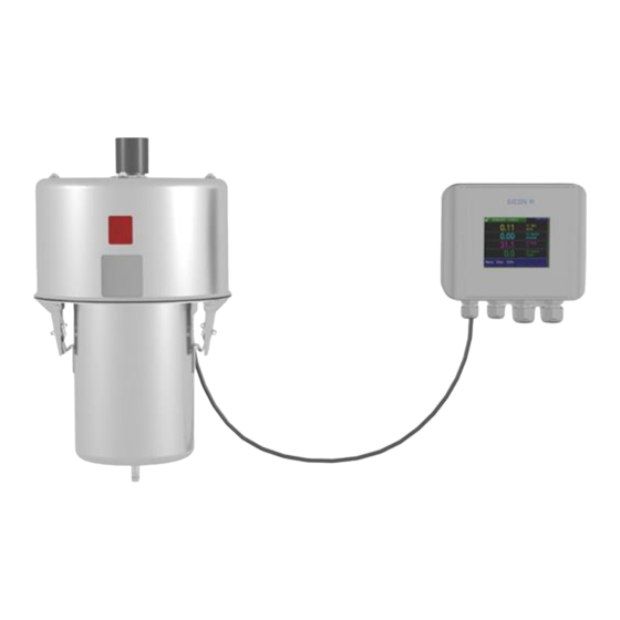
SICON-C portable control unit, can be connected to the SIPORT 2 or connec- tion box via cable Overview of a measuring point with SICON only Figure 2: Overview of a measuring point with VisGuard 2 In-situ connected to the SICON VisGuard 2 In-situ... -
Page 12: Overview Of A Multiple Measuring Point With Sicon M
Instruction Manual VisGuard 2 Instrument overview Overview of a multiple measuring point with SICON M Up to eight VisGuard 2 instruments can be connected and operated on the SICON M. Figure 3: Overview of a multiple measuring point with VisGuard 2 ... -
Page 13: Designation Of The Components
Observe the Instruction Manual Observe the disposal information A red sticker is attached to the VisGuard 2 (arrow). This dis- tinguishes it from instruments with a s imilar appearance. Figure 5: Red sticker for identifying the VisGuard 2 14162E/2... -
Page 14: Designation Of The Sicon (M/-C)
Instruction Manual VisGuard 2 Instrument overview 2.4.2 Designation of the SICON (M/-C) The SICON (M/-C) control unit is fitted with the following rating plate: Figure 6: Designation of the SICON-C Manufacturer Country of origin Product name Serial number ... -
Page 15: Designation Of The Siport 2
Instrument overview Instruction Manual VisGuard 2 2.4.3 Designation of the SIPORT 2 The SIPORT 2 connection box is fitted with the following rating plate: Figure 7: Rating plate on SIPORT 2 Manufacturer Country of origin Product name Serial number ... -
Page 16: Scope Of Supply And Accessories
Instruction Manual VisGuard 2 Instrument overview Scope of supply and accessories 2.5.1 Standard scope of supply for the VisGuard 2 Pcs. Art. no. Name View In-situ Extractive 120688 VisGuard 2 In-situ 120686 VisGuard 2 Extractive (extraction length 30 .. 500 m) -
Page 17: Optional Scope Of Supply For The Visguard 2
German French English 14165 Reference Manual German English 14166 Brief Instructions German French English 2.5.2 Optional scope of supply for the VisGuard 2 PCS. ART. NO. NAME VIEW VARIANT 120290 SICON-C portable control unit 112677 Checking unit 120342 Junction box... - Page 18 Instruction Manual VisGuard 2 Instrument overview PCS. ART. NO. NAME VIEW VARIANT Reference Manual 120802 Sample heater 24 VDC/10 W 118358 High-temperature cable, 8-pin, length by meter, for connection to the SIPORT 2 120393 High-temperature cable, 8-pin incl. connector, L = 1.5...
-
Page 19: Technical Data For The Visguard 2
4-way current in- For SICON (M) 119045 24 VDC mains de- 20 W, IP66, input vice 100 to 240 VAC Technical data for the VisGuard 2 General: Data Values Measuring principle Scattered light measurement Measurement span 0 .. 1000 PLA or 0 .. 3000 mE/m... - Page 20 100 .. 240 VAC; 47 .. 63 Hz Power consumption 25 W (maximum) VisGuard 2 In-situ, with sample heater: 24 W / 45 VA VisGuard 2 In-situ, without sample heater: 12 W / 27 VA Interfaces Profibus DP, Modbus RTU with repeater, StromRel module;...
- Page 21 Instrument overview Instruction Manual VisGuard 2 SICON (M): Data Values Service voltage 24 VDC Power consumption 5 W + photometer Display ¼ VGA with touchscreen Resolution: 320 x 240 pixels with 3.5" diagonal Outputs/inputs Outputs: 4 x 0/4 .. 20 mA, galvanically isolated up to max. 50 V relative to ground and max.
-
Page 22: General Safety Points
Penetration of moisture as well as condensation on the electrical components du r- ing servicing duty. If moisture enters the instrument, the VisGuard 2 can be damaged. Work on the inside of the instrument may be performed only in a dry room and at room CAUTION! temperature. -
Page 23: Residual Risk
General safety points Instruction Manual VisGuard 2 Residual risk According to the risk assessment of the applied safety directive DIN EN 61010-1, there remains the risk of the displayed measuring values being incorrect. This risk can be reduced with the following measures: ... -
Page 24: Preventing Undesirable Online Access Attempts
General safety points Preventing undesirable online access attempts SIGRIST instruments are equipped with an integrated web user interface and Modbus TCP interface, thus offering state -of-the-art administration and control possibilities. However, if these are connected directly to the Internet, then any I n- ternet user can in principle access your instrument and change the configuration. -
Page 25: Mounting
General information on mounting the VisGuard 2 Figure 8: Installation position The VisGuard 2 must not be installed in the direct flow area of the ventilation system as different wind speeds and sandblasting effects can cause measuring faults. ... - Page 26 Instruction Manual VisGuard 2 Mounting Mount the VisGuard 2 as follows: WORKSTEP ADDITIONAL INFO / IMAGES Attach the screws in the measuring position according to the VisGuard2-MB dimension sheet. Fasten the VisGuard 2 in place. 14162E/2...
-
Page 27: Distances And Corresponding Cable Cross-Sections
Mounting Instruction Manual VisGuard 2 Distances and corresponding cable cross-sections The maximum distance (X) between the photometer and connection box is limited and de- pends on the cable cross-section used and the possible use of a 24 VDC sample heater. -
Page 28: Mounting The Optional Junction Box
Instruction Manual VisGuard 2 Mounting Mounting the optional junction box A junction box is recommended in the event of longer cable distances. This should be positi- oned close to the photometer. The junction box is fastened using four screws on a solid, l e- vel surface according to the drawing VDV1-MB (Section 16). -
Page 29: Installing The 230 Vac Sample Heater On The Visguard 2
Mounting Instruction Manual VisGuard 2 Installing the 230 VAC sample heater on the VisGuard 2 Proceed as follows to install the sample heater: WORKSTEP ADDITIONAL INFO / IMAGES Remove the splash guard from the sample inlet of the VisGuard 2. -
Page 30: Mounting The Sicon (M)
Instruction Manual VisGuard 2 Mounting Mounting the SICON (M) WORKSTEP ADDITIONAL INFO / IMAGES Open the shutters. Fasten the control unit to the wall using four M4 x 10 hexagon socket screws. 14162E/2... -
Page 31: Electrical Installation
Electrical installation Instruction Manual VisGuard 2 Electrical installation Safety pointers for the electrical connection The improper electrical connection of the components can be potentially fatal. The components can also be damaged. Note the following basic principles for the electronic connection: ... -
Page 32: Installation With Siport 2
Instruction Manual VisGuard 2 Electrical installation Installation with SIPORT 2 5.2.1 Connecting the SIPORT 2 The cable glands must be adjusted according to the outer diameter of the cables. The following cable glands are available: 2 x 8 .. 17 mm 3 x 8 .. -
Page 33: Connecting The Siport 2 Without Housing
Electrical installation Instruction Manual VisGuard 2 A high-temperature cable must be used for the connection. Establish the electrical conne c- tions in the SIPORT 2 as follows: TERMINAL MEANING CABLE COLOR REMARKS NUMBER (SIGRIST) 8 WIRES Black and white Photometer connection (Figure 11, pos. -
Page 34: Profibus Dp: Overview And Installation
Instruction Manual VisGuard 2 Electrical installation 5.2.3 Profibus DP: Overview and installation To connect to the Profibus DP, the Profibus module must be integrated in the SIPORT 2. In the Digi.interf. \ General menu, the Module type must be set to Profibus DP and the Module location to SIPORT 2. -
Page 35: Profinet Io: Overview And Installation
Electrical installation Instruction Manual VisGuard 2 5.2.4 Profinet IO: Overview and installation To connect to the Profinet IO, the Profinet IO module must be integrated in the SIPORT 2. The module has an internal switch and provides two Ethernet ports. -
Page 36: Modbus Rtu With Repeater: Overview And Installation
Instruction Manual VisGuard 2 Electrical installation 5.2.5 Modbus RTU with repeater: Overview and installation To connect to the Modbus RTU with repeater, a Modbus module must be integrated in the SIPORT 2. In the Digi.interf. \ General menu, the Module type must be set to Modbus and the Module location to SIPORT 2. - Page 37 Electrical installation Instruction Manual VisGuard 2 The terminals of the RTU module are configured as follows: TERMINALS MODBUS POTENTIAL FUNCTIONAL DESCRIPTION GND – to ground potential Ground po- Connection of the GND line tential RS485-A IN Data connection RS485-B IN...
-
Page 38: Stromrel Module: Overview And Installation
Instruction Manual VisGuard 2 Electrical installation 5.2.6 StromRel module: Overview and installation The configuration of the StromRel module is described in the Section 8.3/ Section 8.5. In the Digi.interf. \ General menu, the Module type must be set to StromRel and the Module location to SIPORT 2. -
Page 39: Current/Digi. Input For Siport 2
Electrical installation Instruction Manual VisGuard 2 5.2.7 Current/Digi. input for SIPORT 2 Two 0/4 .. 20 mA current inputs are available. Both active and passive sensors can be connected. A digital input is available for connecting a fan with tacho output or a pressure monitor. -
Page 40: Connecting An External Analog Sensor
Instruction Manual VisGuard 2 Electrical installation 5.2.8 Connecting an external analog sensor Connection is made on the optional current/Digi. input add-on module according to Section 5.2.7. A passive 4 .. 20 mA sensor is connected between terminals 1 (24V) and 2 (A1) or 4 (A2). -
Page 41: Connecting The Optional Junction Box
Electrical installation Instruction Manual VisGuard 2 5.2.10 Connecting the optional junction box The photometer is connected to the junction box via a connector (1). There is the possibility of connecting the junction box to the SICON-C (2) portable control unit. This enables opera- tion directly on the photometer during servicing duties. - Page 42 Instruction Manual VisGuard 2 Electrical installation Establish the electrical connections in the junction box as follows: TERMINAL CABLE COLOR CABLE COLOR REMARKS DESIGNATION (SIGRIST) 8 WIRES (SIGRIST) 4 WIRES WITH SIPORT 2 WITH SICON Black Blue Are connected to each...
-
Page 43: Connecting The Sicon (M)
Electrical installation Instruction Manual VisGuard 2 Connecting the SICON (M) 5.3.1 Removing the cover from the SICON (M) WORKSTEP ADDITIONAL INFO / IMAGES Open the shutters. Loosen the fastening screws on the cover. Open the cover. Fasten the cover with the cover clamp. To do this, remove the cover clamp from the park po- sition (X) and fasten the cover in position (Y). -
Page 44: Overview Of The Opened Sicon (M) Control Unit
Instruction Manual VisGuard 2 Electrical installation 5.3.2 Overview of the opened SICON (M) control unit Figure 18: Overview of SICON (M) Park position for cover clamp microSD card (card for log data) USB connection Ethernet connection ... -
Page 45: Installation Of The Sicon (M)
Electrical installation Instruction Manual VisGuard 2 5.3.3 Installation of the SICON (M) Life-threatening voltage inside the instrument. Connecting electrical lines can be extremely dangerous. Instrument parts may also be da- maged. Local regulations for electrical installations must be observed at all times. -
Page 46: Connecting The Field Bus Interfaces (Optional)
Instruction Manual VisGuard 2 Electrical installation Connecting the field bus interfaces (optional) Information on commissioning the field bus interfaces can be found in the Reference Handbook. 5.4.1 Overview of Modbus RTU and Profibus DP Figure 20: Overview of field bus interfaces ... -
Page 47: Terminal Assignment Of Modbus Rtu/Profibus Dp
Electrical installation Instruction Manual VisGuard 2 5.4.2 Terminal assignment of Modbus RTU/Profibus DP The Profibus DP / Modbus RTU terminals are assigned as follows: TERMINALS MODBUS / PROFIBUS FUNCTIONAL DESCRIPTION Ground IN Connection for cable shielding 12 A RS485-A IN... -
Page 48: Profinet Io: Overview And Installation In The Sicon
Instruction Manual VisGuard 2 Electrical installation 5.4.3 Profinet IO: Overview and installation in the SICON To connect to the Profinet IO, the Profinet IO module must be integrated in the SICON. The module has an internal switch and provides two Ethernet ports. -
Page 49: 4-Way Current Output Module: Overview And Installation
Electrical installation Instruction Manual VisGuard 2 5.4.4 4-way current output module: Overview and Installation The configuration of the 4-way current output module is described in the Section 8.3. Figure 22: Position of the 4-way current output 4-way current output module... -
Page 50: 4-Way Current Input Module: Overview And Installation
Instruction Manual VisGuard 2 Electrical installation 5.4.5 4-way current input module: Overview and Installation The configuration of the 4-way current input module is described in the Reference Hand- book. Figure 23: Position of the 4-way current input module ... -
Page 51: Overview Of Hart
Electrical installation Instruction Manual VisGuard 2 5.4.6 Overview of HART Information on commissioning the field bus interfaces can be found in the Reference Handbook. Figure24: Position of the HART module in the SICON (M) Field bus interface (connection HART terminals print) for HART. -
Page 52: Connecting An External Analog Sensor
Instruction Manual VisGuard 2 Electrical installation 5.4.8 Connecting an external analog sensor Connection is made on the 4-way current input module (Section 5.4.5). A passive 4 .. 20mA sensor is connected between terminal 9 (24V) of the SICON and terminal 2 (In 1+) of the 4-way current input. -
Page 53: Connecting The Optional 24 Vdc Power Supply
Electrical installation Instruction Manual VisGuard 2 5.4.10 Connecting the optional 24 VDC power supply Life-threatening voltage due to accidentally released voltage -carrying wires. The wires of the supply connection must be secured with cable ties so that if one wire accidentally becomes loose no other parts can be charged with voltage. -
Page 54: Commissioning
Instruction Manual VisGuard 2 Commissioning Commissioning The initial start-up of the web user interface is described in the Reference Manual. Proceed with the initial start-up in accordance with the following table: WORKSTEP ADDITIONAL INFO / IMAGES Ensure that all components are correctly moun- Section 4 and Section 5 ted and connected. -
Page 55: Additional Measuring Channels For Smoke Measurement
Additional measuring channels for smoke measurement The VisGuard 2 can be used as both a visibility detector and smoke detector. To do this, a mode is available where the VisGuard 2 acts in the same way as a FireGuard 2 smoke detec- tor (see Reference Manual). -
Page 56: Operation
Instruction Manual VisGuard 2 Operation Operation Operation basics In this document we describe the practical examples only for the first steps of the menu con- figuration. All other setting options are described in the Reference Handbook. Operation us- ing the web user interface is described in detail in the Reference Manual. -
Page 57: Led Display On The Photometer
Operation Instruction Manual VisGuard 2 LED display on the photometer The VisGuard 2 has a red LED (circle) in order to indicate the most important events during measuring operation without a control unit. Figure 26: Position of the LED display... -
Page 58: Connecting Sicon-C To Siport 2
Instruction Manual VisGuard 2 Operation Connecting SICON-C to SIPORT 2 The SICON-C (2) is connected to the SIPORT 2 (1) on the connector (X). The protection cover on the SIPORT 2 must be removed beforehand. If the SIPORT 2 is connected to the service voltage, the SICON-C starts automatically. -
Page 59: Connecting The Sicon-C To The Siport 2 Without Housing
Operation Instruction Manual VisGuard 2 Connecting the SICON-C to the SIPORT 2 without housing The SICON-C (2) is connected to the SIPORT 2 without housing (1) on the connector (X). If the SIPORT 2 is connected to the service voltage, the SICON-C starts automatically. -
Page 60: Control Elements In Measuring Operation
Instruction Manual VisGuard 2 Operation Control elements in measuring operation Figure 29: Control elements in measuring operation Menu button Valu button Calls up the menu structure. Sec- Numerical representation of the meas- tion 7.6 uring values. Section 7.7 ... -
Page 61: Info Button
Operation Instruction Manual VisGuard 2 Info button When you press the Info button, a general overview of the instrument settings appears. These are described below: 7.8.1 Info button, screen 1 Figure 30: Info button, screen 1 Information about the available Status of the inputs/outputs ... -
Page 62: Info Button
Instruction Manual VisGuard 2 Operation 7.8.2 Page 2, Info button Figure 31: Info screen, page 2 Contact information Display of up to 5 pending fault mes- sages 14162E/2... -
Page 63: Diag Button
Operation Instruction Manual VisGuard 2 Diag button When you press the Diag button, a diagram appears which graphically s hows the measuring values over a certain period of time. Figure 32: Graphic representation of the measuring values Graphic representation of the... -
Page 64: Functions Of The Log Screen (Log Button)
Instruction Manual VisGuard 2 Operation 7.10 Functions of the log screen (Log button) The screen logger works independently of the data logger, which is set in the Logger menu and writes to the microSD card. The screen logger records the data of the last 32 days in one minute intervals. The data can be called up from the Log menu. -
Page 65: Display In Measuring Operation
Operation Instruction Manual VisGuard 2 7.11 Display in measuring operation Figure 34: Display in measuring operation Measuring value(s) Status line For values which are greater than In normal operation, the status line is the maximum measuring range, no green and shows the date and time. -
Page 66: Activating And Deactivating The Screen Lock
Instruction Manual VisGuard 2 Operation 7.12 Activating and deactivating the screen lock MANIPULATION Press the lock icon top left. Within one second press the key bottom at the outside right. Depending on the initial state, the lock icon changes as follows:... -
Page 67: Switching To Service Mode
Operation Instruction Manual VisGuard 2 7.13 Switching to service mode The system is configured in service operation. The measuring procedure is interrupted and the main menus appear on the display. Service operation is accessed as follows: MANIPULATION ADDITIONAL INFO / IMAGES Press the Menu button. -
Page 68: Control Components In Service Mode
Instruction Manual VisGuard 2 Operation 7.14 Control components in service mode 7.14.1 Input elements in service mode Figure 35: Input elements in service mode Path specification Page number / total number of pages Main menus... -
Page 69: Numerical Entry
Operation Instruction Manual VisGuard 2 7.14.2 Numerical entry The following screen is for entering numbers and data: Figure 36: Numerical entry Parameter name Entered values Prefix: For entering very large or Numerical entry very small values. This can be done as follows: 1. -
Page 70: Single Selection Of Functions
Instruction Manual VisGuard 2 Operation 7.14.3 Single selection of functions The single selection is identifiable by the ESC button below right. The currently selected function is green. Use the Up/Down arrows to navigate the options in long lists. Use the ESC button to cancel the entry. -
Page 71: Settings
Settings Instruction Manual VisGuard 2 Settings Setting the operating language MANIPULATION ADDITIONAL INFO / IMAGES Press the Menu button. Set the access code and confirm with OK. Factory setting is 0. Press the Configuration button to access lan- If the desired menu does not guage selection. -
Page 72: Setting The Date And Time
Instruction Manual VisGuard 2 Settings Setting the date and time MANIPULATION ADDITIONAL INFO / IMAGES Press the Menu button. Set the access code and confirm with OK. Factory setting is 0. Press the Configuration button. If the desired menu does not appear, press the arrow bottom right. -
Page 73: Setting The Current Outputs
Settings Instruction Manual VisGuard 2 Setting the current outputs MANIPULATION ADDITIONAL INFO / IMAGES Press the Menu button. Set the access code and confirm with OK. Factory setting is 0. Press the Curr. outputs button. Select between C1 .. n. -
Page 74: Setting The Limits
Instruction Manual VisGuard 2 Settings Setting the limits The limits have to be configured accordingly so that they are not only displayed, but that the outputs are also switched.Section 8.5 MANIPULATION ADDITIONAL INFO / IMAGES Press the Menu button. Set the access code and confirm with OK. -
Page 75: Upper And Lower Threshold Value Of A Limit
Settings Instruction Manual VisGuard 2 8.4.1 Upper and lower threshold value of a limit A maximum of eight limits with upper and lower threshold values can be programmed. If the operating mode is set to Exceeded, then while the upper threshold value is... -
Page 76: Setting The Outputs
Instruction Manual VisGuard 2 Settings Setting the outputs MANIPULATION ADDITIONAL INFO / IMAGES Press the Menu button. Set the access code and confirm with OK. Factory setting is 0. Press the Inp./outputs button. If the desired menu does not appear, press the arrow at the bot- tom right. -
Page 77: Setting The Recalibration
Settings Instruction Manual VisGuard 2 Setting the recalibration If the Auto start recal. parameter is activated, then the installation of the checking unit in the photometer automatically triggers a recalibration. This allows servicing duties to be ca r- ried out without the use of a control unit. The state of the recalibration can be monitored via the LED display (Section 7.2). -
Page 78: Setting The Profinet Io Parameters
Instruction Manual VisGuard 2 Settings Setting the Profinet IO parameters This setting only has to be carried out if the optional Profinet IO module is used. MANIPULATION ADDITIONAL INFO / IMAGES Press the Menu button. Set the access code and confirm with OK. -
Page 79: Setting The Modbus Rtu Parameters
Settings Instruction Manual VisGuard 2 Setting the Modbus RTU parameters This setting only has to be carried out if the optional Modbus module is used. MANIPULATION ADDITIONAL INFO / IMAGES Press the Menu button. Set the access code and confirm with OK. -
Page 80: Setting Or Changing The Access Code
Enter the access code and confirm with OK. Press the Meas button. The instrument is in measuring op- eration again. A forgotten access code can be cleared only by a SIGRIST service engineer. Enter your personal access code here: 14162E/2... -
Page 81: Backup Configured Data
Settings Instruction Manual VisGuard 2 8.11 Backup configured data These measures can be of use to the service engineers for service purposes. MANIPULATION ADDITIONAL INFO / IMAGES Press the Menu button. Set the access code and confirm with OK. Factory setting is 0. -
Page 82: Servicing
Vis- measuring results. Guard2/Seal-BA drawing. Operator Replacing the filter For ensuring the required air cartridge in the VisGuard 2 flow. In-situ. Section 9.4 Every 5 years Operator Replacing the fan on the Obligatory measure for main- VisGuard 2 In-situ. -
Page 83: Cleaning The Outside Of The Visguard 2
Dirt on the outside of the instrument does not have any effect on the measuring results. On In-situ instruments, the supplied protection covers must be attached before all forms of cleaning: Position During operation For cleaning Sample inlet at top Sample inlet at bot- Figure 40: Protection covers on the VisGuard 2 In-situ 14162E/2... -
Page 84: Cleaning The Sample Inlet
The following procedure describes how to clean the sample inlet: Soiling of the optics due to improper cleaning of the sample inlet. Using brushes or pipe cleaners when cleaning the sample inlet can lead to soiling of the op- tics in the VisGuard 2. CAUTION! WORKSTEP... -
Page 85: Replacing The Filter Cartridge In The Visguard 2 In-Situ
Servicing Instruction Manual VisGuard 2 Replacing the filter cartridge in the VisGuard 2 In-situ The filter cartridge can be replaced as follows: WORKSTEP ADDITIONAL INFO / IMAGES Interrupt the service voltage to the photome- ter. Remove the housing from the VisGuard 2. - Page 86 Instruction Manual VisGuard 2 Servicing WORKSTEP ADDITIONAL INFO / IMAGES Clean the holder (arrow). Position the new filter cartridge (A) on the hol- der and push upwards until the cartridge snaps into place. Reattach the housing and fasten in place with the clamps.
-
Page 87: Replacing The Fan On The Visguard 2 In-Situ
Servicing Instruction Manual VisGuard 2 Replacing the fan on the VisGuard 2 In-situ The fan can be replaced as follows: WORKSTEP ADDITIONAL INFO / IMAGES Interrupt the service voltage to the photome- ter. Remove the housing from the VisGuard 2. - Page 88 Instruction Manual VisGuard 2 Servicing WORKSTEP ADDITIONAL INFO / IMAGES Remove the old fan from the housing by remo- ving the four screws (arrows). Fasten the new fan in place on the base in the housing with the four screws. Ensure that the cable outlet is finally positioned facing dow n- wards (circle).
-
Page 89: Recalibrating The Visguard 2
The automatic triggering of a recalibration can be activated under Re- calibration \ General \ Auto start recal.. The nominal values on two checking units can be saved in the VisGuard 2. The checking units are identified via a serial number. ... - Page 90 Instruction Manual VisGuard 2 Servicing WORKSTEP ADDITIONAL INFO / IMAGES Insert the checking unit into the sample inlet as follows: 1. Remove the protective casing from the checking unit. 2. Insert the checking unit into the sample in- let. Ensure that the pin (A) is aligned to the groove (B) on the sample inlet.
-
Page 91: Automatically Triggered Adjustment
Servicing Instruction Manual VisGuard 2 9.6.4 Automatically triggered adjustment Alarms can also be triggered as a result of the automatically triggered adjustment. WARNING! The following procedure describes how automatic adjustment is made. However, this can only be carried out when Auto start recal. has been activated according to Section 8.6. - Page 92 Flashes zero times = clean If the LED flashes more than five times, then Flashes up to ten times = soiling the soiling level is too high. The VisGuard 2 limit reached must be cleaned according to the servicing schedule.
-
Page 93: Changing The Battery In The Control Unit
Servicing Instruction Manual VisGuard 2 Changing the battery in the control unit WORKSTEP ADDITIONAL INFO / IMAGES Unplug the connection tot he instrument. Open the flaps on the instrument. Loosen the four screws (circles). Open the cover of the instrument. -
Page 94: Troubleshooting
Instruction Manual VisGuard 2 Troubleshooting 10 Troubleshooting 10.1 Pinpointing malfunctions MALFUNCTION MEASURE No reading Check whether the supply voltage is connected. Fault message in the display Analyze the fault message according to the following sctions. The reading appears to be Carry out recalibration. - Page 95 Troubleshooting Instruction Manual VisGuard 2 The following warning messages can be displayed: WARNING DESCRIPTION POSSIBLE CAUSES MESSAGE V IN The input voltage is outside The service voltage is faulty the permitted range (20 .. 26 VDC). SENSOR CHECK...
-
Page 96: Fault Messages And Effect On Operation
Instruction Manual VisGuard 2 Troubleshooting 10.3 Fault messages and effect on operation FAULT If a fault occurs during operation, it has the following effects: A fault is a malfunction which prevents correct measurement value acquisition. The measuring values of the concerned photome- ter go to 0. - Page 97 Troubleshooting Instruction Manual VisGuard 2 FAULT MESSAGE DESCRIPTION POSSIBLE CAUSES LIGHTSOURCE 1 The detector for monitoring Defective light source. Service technician the light source receives no light from the corresponding light source. IO PORT The connection between the Cable disconnected.
-
Page 98: Prioritized Fault Messages And Their Effect On Operation
Instruction Manual VisGuard 2 Troubleshooting 10.4 Prioritized fault messages and their effect on operation When there is a prioritized fault, the cause of the malfunction is serious. CAUTION! PRIO (PRIORITIZED FAULT) If a prioritized fault occurs during operation, it has the following effects: ... -
Page 99: Customer Service Information
A current list of all SIGRIST country representatives is available online at www.photometer.com. Please have the following information ready when you contact a SIGRIST service point or customer service: ... -
Page 100: Decommissioning/Storage
There are no special requirements for storing the instruments. However, please note the following information: The VisGuard 2 and the belonging components contains electronic parts. Storage for such components must fulfill the usual conditions. It is important to note that the stora- ge temperature must be between -30 and +55 °C. -
Page 101: Packaging/Transport/Returning
The original packaging materials should be used for packaging the VisGuard 2 if possible. If the original packaging is no longer available, note the following information: ... -
Page 102: Disposal
Instruction Manual VisGuard 2 Disposal 14 Disposal Disposal of the system and its peripheral devices is to be carried out in compliance with regi- onal statutory regulations. The system has no environmentally damaging sources of radiation. The materials listed be-... -
Page 103: Spare Parts List
Reference Manual (for replacing the con- 118361 Cable gland M16 x 1.5, straight trol cable on the VisGuard 2) Reference Manual (for replacing the con- 116387 O-ring FPM 12 x 1.5 trol cable on the VisGuard 2) ... -
Page 104: Appendix
Instruction Manual VisGuard 2 Appendix 16 Appendix 14162E/2... - Page 105 Appendix Instruction Manual VisGuard 2 Thi s page i s i n t e nt i o nal l y bl a nk 14162E/2...
-
Page 106: Index
Instruction Manual VisGuard 2 Index 17 Index Internet security ..........24 Access code, set ..........80 Article numbers ..........103 Language ............71 Limits, definition ..........75 Log ..............64 Cable cross-section .......... 27 Cable ties............53 CE mark............8 Main switch .............31 Checking units ..........89 Mains device ............53... - Page 107 Index Instruction Manual VisGuard 2 Setting the outputs .......... 76 Touchscreen.............56 SICON M ............12 Transport ............101 SICON M, overview .......... 44 SICON, cover ........... 43 SIPORT 2 connection print......... 28 USB connection ..........44 Spare parts.............103 Use restrictions ..........8 Storage ............100...
- Page 108 SIGRIST-PHOTOMETER AG Tel. +41 41 624 54 54 Hofurlistrasse 1 +41 41 624 54 55 CH-6373 Ennetbürgen inf o@photome ter. com Switzerland w w w .photome ter.com...
Need help?
Do you have a question about the VisGuard 2 and is the answer not in the manual?
Questions and answers