
Summary of Contents for LockMasters Magnum Bullet II Pro 557 Series
- Page 1 Magnum Bullet II™ - MAG55701 Magnum Drill Rig - MAG55702 Magnum Pro™ Drill Rig - MAG55703 (Magnum Pro is a combination of the MAG55701 & MAG55702) OWNERS MANUAL & OPERATING INSTRUCTIONS...
- Page 2 Wear hearing protection during extended use of power tools and dust mask for dusty operations. • STAY ALERT. USE COMMON SENSE. Watch what you are doing. Do not operate tool when you are tired or under influence of drugs. • REMOVE ADJUSTING KEYS AND WRENCHES. Form habit of checking to see that keys and adjusting wrenches are removed from tool before turning it on. • AVOID ACCIDENTAL STARTING. Don’t carry plugged in tool with finger on switch. Be sure the switch is OFF before being plugged in. • DON’T OVERREACH. Keep proper footing and balance at all times. • BEFORE CONNECTING THE TOOL to a power supply (receptacle, outlet, etc.) be sure the voltage supplied is the same as that specified on the tool’s nameplate. A power supply with voltage greater than that specified for the tool can result in seri- ous injury to the user - as well as damage to the tool. If in doubt, DO NOT PLUG IN THE TOOL. Using a power supply with voltage less than the nameplate rating is harmful to the motor. NOTE “Volts AC” designated tools are for Alternating Current 50-60 Hz only. “Volts DC” designated tools are for Direct Current. Do not use AC designated tools with DC power supply. Do not use electronic speed controlled tools with DC power supply. Copyright © 12/2015 Lockmasters, Inc.
- Page 3 DISCONNECT TOOLS. When not in use, before servicing, or when changing blades, bits, cutters, etc. • STORE IDLE TOOLS. When not in use, tools should be stored in dry, high or locked up place - out of the reach of children. • DO NOT ALTER OR MISUSE TOOL. These tools are precision built. Any alterations or modifications not specified is misuse and may result in a dangerous condition. • THE USE OF ANY ACCESSORIES not specified in this manual may create a haz- ard. • MAINTAIN TOOLS WITH CARE. Keep tools sharp and clean for better and safer performance. Follow instructions for lubricating and changing accessories. Inspect tool cords periodically and if damaged, have repaired by authorized service facili- ty. Inspect extension cords periodically and replace if damaged. Keep handles dry, clean and free from oil and grease. • CHECK DAMAGED PARTS. Before further use of the tool, a guard or other part that is damaged should be carefully checked to determine that it will operate properly and perform its intended function. Check for alignment of moving parts, binding of moving parts, breakage of parts, mounting, and any other conditions that may affect its operation. A guard or other part that is damaged should be promptly and properly repaired or replaced. Have defective switches replaced. Do not use tool if switch does not turn it on or off. • ALL REPAIRS, ELECTRICAL OR MECHANICAL should be attempted only by trained repairmen. Copyright © 12/2015 Lockmasters, Inc.
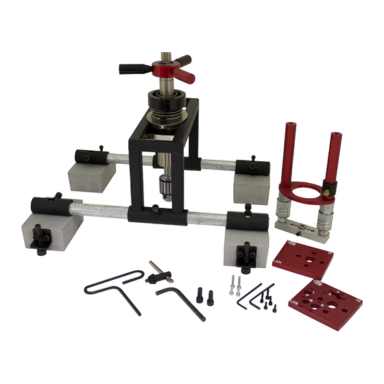
- Page 4 Magnum Bullet II™ MAG55701 Frame Tubes Magnum Drill Rig Magnetic Feet MAG55702 Magnetic Feet Tubes Jack Screws Magnum Pro™ Drill Rig MAG55703 (Pro is a combination of the MAG55701 & MAG55702) Copyright © 12/2015 Lockmasters, Inc.
- Page 5 Note: Other templates available for other locks. Attaching The Drill Template 4a. The mounting pattern for the Drill Point Template matches the Dial Ring mounting pattern in the four (4) mounting positions, RH, LH, VU, VD. b. Align the selected drill template with the dial ring mounting pattern on the safe. c. Attach the selected drill template to the safe with the two (2) 8-32 x 3/8” socket head cap 4 (a) Attaching the Drill template screws provided and tighten securely. 4 (b) Template attached. Copyright © 12/2015 Lockmasters, Inc.
- Page 6 Attach the Quick Disconnect Bullet Tower to the Bullet Drill Base. 5c. Attaching the Quick Disconnect Bullet Tower to the Bullet Drill Base. Operating the Magnum Bullet II 6a. With the Barrel and Quill Assembly in hand, and viewing from the chuck end, hold the chuck collar with one hand while rotating the chuck sleeve counterclockwise with the other hand. Open chuck to approximate drill bit diameter. 6a. Prepping the Barrel and Quill Assembly by rotating the chuck sleeve counterclock- b. Insert a clean bit up to the drill bit flutes for wise, opening the chuck to approximate drill small bits, or as far as it will go for larger bits. bit diameter. Inserting a clean drill bit in the Barrel and Quill Assembly. Copyright © 12/2015 Lockmasters, Inc.
- Page 7 Barrel and Quill Assembly. You are now ready to penetrate the safe. “S” Model NOTE: If you have the style Barrel with a spindle that protrudes from 7b. Insert the nut driver into the hex drive the back, tighten the Drill motor on to the socket, now you are ready to penetrate spindle. the safe. Copyright © 12/2015 Lockmasters, Inc.
- Page 8 Inspect the drill bit for damage and replace if necessary. d. When drilling with successively longer bits (4”, 6”, 8”, etc.) to penetrate a thick door, simply remove the Barrel and Quill Assembly from the Quick Release Coupling and change drill bits. Be sure to back off the Quill until it stops and then turn clockwise 1/2 turn before replacing the Barrel and Quill Assembly into the Quick Release Coupling. Copyright © 12/2015 Lockmasters, Inc.
- Page 9 Place the Magnetic Feet (4) on the Pipes by sliding the Magnetic Feet Tubes over the pipe. Note: For most applications there should be approximately 1/2 inch (13 mm) of Pipe protruding from the left and right sides of the Magnetic Feet Tubes. 3c. Placing the Magnetic Feet (4) on the Pipes. Copyright © 12/2015 Lockmasters, Inc.
- Page 10 Attach with the two (2) socket head machine screws provided and tighten firmly. Note: The notched side of the Plate goes against the Frame. 3g. Attaching the Coupling to the center of the frame. h. Pick up the assembled Drill Rig Frame (minus the Barrel and Quill Assembly) and position it on the safe or vault door with the center of the Coupling over the drill point. 3h. Placing the assembled Drill Rig Frame on the Safe or Vault Door. Copyright © 12/2015 Lockmasters, Inc.
- Page 11 Operating the Magnum 557 with Magnets 4a. With the Barrel and Quill Assembly in hand, and viewing from the chuck end, hold the chuck collar with one hand while rotating the chuck sleeve counterclockwise with the other hand. Open chuck to approximate drill bit diameter. b. Insert a clean bit into the drill bit flutes for small bits, or as far as it will go for larger bits. 4a. Holding the chuck collar and rotating the chuck sleeve counterclockwise. Copyright © 12/2015 Lockmasters, Inc.
- Page 12 Feet Tubes to snug (do not over-tighten). Loosen the Frame’s cap screws on the Pipes to move the Frame to the left or right. Once in position re-tighten the Frame’s cap screws 5a. (1) Tightening the cap screws on Magnetic Feet, (2) Loosening the Frame’s cap screws, (3) Positioning the Frame from Left to Right. b. Vertical Alignment (Top to Bottom) Loosen the (2) mounting screws on the Quick Release Coupling and slide the Coupling up or down and re-tighten the screws once in position. (1) Loosening the mounting screws on the Quick Release Coupling. (2) Positioning the Barrel & Quill Assembly Copyright © 12/2015 Lockmasters, Inc.
- Page 13 Barrel and Quill Assembly. Release the drill bit from the chuck. Use a pair of pliers to hold the shank of the drill bit and turn the drill bit in a counter-clockwise rotation to loosen from workpiece. Inspect the drill bit for damage and replace if necessary. Copyright © 12/2015 Lockmasters, Inc.
- Page 14 2. How can I angle drill with the Magnum? a. The Magnum 357 and the old 457 Magnum had a three part frame that allowed angle drilling in 5 degree increments up to 25 degrees. The 557 Magnum does not have this capability. b. Use a lever rig, the “Equalizer II”. Call Lockmasters, Inc. Customer Service. • Press coupler ring and slide barrel and quill assembly until the drill bit touches the surface, release coupling. 3. Is it possible to drill at a compound angle? a. Only with the Magnum 357 and the old 457 Magnum with magnets. With the drill rig installed at the desired position for angle drilling, extend the jack screws on the magnetic feet and rotate the entire rig to the desired position. Make sure you retract the jack screws...
- Page 15 High Speed Steel bits should be used to begin the hole. This bit can be used to drill the skin, some insulation, mild steel or stainless steel. Cobalt bits may also be used on any of these materials. A cobalt bit is more expensive than a high speed steel bit, but it is harder and so will hold its edge much longer. Being harder, it is slightly more brittle and more likely to break. Carbide-Tipped bits have a wedge of tungsten carbide at the tip. These bits are designed for drilling hard metals. There are basically two types, straight-fluted and spiral-fluted, and each has advantages. The straight-fluted style (Champion) has a greater cross-section and so has a stronger shank. The spiral-fluted style (MP3) will carry chips out of the hole, helping to prevent the bit from binding. One spiral-fluted bit (Mr. Twister) has notches in the cutting edge which increases the cut- ting surface by more than 17%. Carbide-tipped masonry bits are used for drilling concrete, and this is the insulation used in some fire safes. They are not well suited for drilling hard metals, because their cutting edge is sharpened to a very steep angle. Sometimes drilling with a carbide-tipped bit must be alternated with punching to break up or dislodge carbide chips. Solid carbide bits should not be used. They are brittle and may shatter and plug the hole. Diamond-Tipped Core Drill Bits (Diamatip) is used for drilling various types of carbide hard- plate. It is hollow and is filled with a lubricant which flushes debris from the hole. It is more expensive than any other type of bit, but it can save hours of time in penetrating some hardplates. The bit is somewhat fragile, and it would quickly be damaged by any rough protrusions on the hardplate sur- face. Grinding a (used) carbide-tipped bit against the surface to smooth and pocket it, will prepare the surface. Drilling is done with slow speed and light pressure. A hole saw, punch or carbide bit is used to remove the carbide core from the hole. Punches may be needed in some cases to break up or dislodge pieces of brittle hardplate. A variety of (Chisel Punches), (Pin Punches) and (Two Piece Punches) should be available. Drill Motors (Bosch-BOS1194VSR) should have good ventilation and feel comfortable when hand-held. They should draw at least 4.5 amps, to withstand the pressure that may be applied by Copyright © 12/2015 Lockmasters, Inc.
- Page 16 It allows versatility in terms of the angle of drilling, and can be used with a variety of drill motors. A fixed rig (Magnum) attaches to the safe by means of chain, straps, magnetic or pneumatic force (M-4 Vacuum Base Drill Rig). It gives great control over pressure and rate of feed. BARRIER MATERIALS AND TECHNIQUES FOR DRILLING THEM Close attention should be paid to the equipment as it is being used, to determine what tech- niques or tools are appropriate. The sound of the drill motor, the forward progress of the bit in the hole, the condition of the bit and the sound of the bit as it drills — all of these must be monitored as drilling proceeds. The drill motor will be running at maximum speed before the bit contacts the safe. As mate- rial is drilled, this “load” on the motor will cause it to slow down slightly. This will be indicated by the sound of the motor dropping in pitch. If there is an air gap after the material is penetrated, the motor will speed up, because there is now no resistance. But if at this point another layer of material is reached, the drill motor may either speed up or slow down. If the bit is able to drill the second layer, the motor will slow down as the material is being drilled. If the bit is unable to drill it, the motor will speed up as the bit spins on the surface of the material. Copyright © 12/2015 Lockmasters, Inc.
- Page 17 Relsomite is a hard surfacing material bonded to a base metal. It can be drilled with a carbide-tipped drill bit and a fixed drill rig. Use 1000 rpm or less, and steady medium to heavy pressure. If one bit wears out before penetrating, punch the hole sharply with a pointed punch, attempting to crack the surface. Continue drilling with another carbide-tipped bit. Kymloy is made by bonding together tungsten carbide fragments and steel powder. It can be drilled with a drill rig and carbide-tipped drill bit. Carbide Welded hardplate is made by welding a carbide material onto a steel plate. When this is used in a safe, the carbide side will be what the drill hits first. A fixed drill rig, carbide-tipped bits, and low rpm drilling, combined with lots of punching, will succeed. Alternating bits with differ- ent tip angles is often helpful. This may be drilled quicker and more easily with a diamond-tipped core drill, after a carbide-tipped bit is used to smooth the surface. Use a fixed drill rig, slow speed (no more than 500 rpm) and light pressure. After the carbide chip portion has been drilled, use a hole saw of the same diameter to remove the core which has been cut or simply break off the core. Half an hour or more may be necessary to penetrate the hardplate. Carbide Matrix hardplates, such as Shwayder’s “Maxalloy” (also known as “Relsom”) are made by sprinkling carbide chips in a mild steel pan of copper wash. These can be identified by the copper color of the material, and by the way it gouges drill bits. This cannot be penetrated by drilling alone, even if carbide-tipped bits are used. Punching will be necessary to break up and dislodge the carbide chips, and the drilling and punching are alternated and continued until the hole is completed. A diamond-tipped core drill may also be used. Carbide Rods are sometimes used in the door or in the safe, inserted side by side in parallel holes. Punching will fracture these, and alternating drilling and punching will penetrate them. Copyright © 12/2015 Lockmasters, Inc.
- Page 18 Once the pocket is formed, drill as usual. There may be more than one of these, so check with a scope after penetrating each one. Torch-Resistant materials are sometimes found in higher-rated safes. A layer of copper or aluminum will dissipate heat rapidly, preventing a torch from melting the material. Sometimes a layer of rubber will be used, and attempts to penetrate it by torching will release smoke. This will be noticeable and would be detected by a smoke alarm. The smoke would also make breathing difficult for the technician. Copyright © 12/2015 Lockmasters, Inc.
- Page 19 MAG1001DC MAG1002DC 1/4” Diamatip 5/16” Diamatip MRT3/16X4C MRT1/4X10C MRT1/4X4C MRT5/16X6C MAG1001DC4 MAG1003DC MRT1/4X6C MRT5/16X8C 1/4” x 4” Diamatip 3/8” Diamatip MRT1/4X8C MRT3/8X6C MRT1/2X6C salesinfo@lockmasters.com FAX 859.885.7093 www.lockmasters.com 800.654.0637 Copyright © 12/2015 Lockmasters, Inc.
- Page 20 2101 John C. Watts Drive Nicholasville, KY 40356 800.654.0637 • 859.885.6041 • Fax 859.885.1731 www.lockmasters.com • salesinfo@lockmasters.com MAG55701, MAG55702, MAG55703 INSTRUCTIONS U.S. Patent No. 5,984,594. ©2015 Copyright Lockmasters, Inc. All Rights Reserved. Rev. 12/2015...
Need help?
Do you have a question about the Magnum Bullet II Pro 557 Series and is the answer not in the manual?
Questions and answers