Table of Contents
Advertisement
Advertisement
Table of Contents

Summary of Contents for Sankosha DF-100E-V3
-
Page 1: Instruction Manual
DF-100E-V3 Instruction Manual Instruction Manual For your safety, please read this Instruction Manual carefully and understand all instructions before starting operating of the machine. If at any time you have any questions, please do not hesitate to contact us. - Page 2 Welcome Thank you for choosing our DF-100E-V3 (Rotary Form Finisher). This machine was delivered to you after thorough inspection at our plant. Please read this manual carefully for proper usage of this machine. Product Specifications Model DF-100E-V3 Power Single phase 230V 50/60Hz...
-
Page 3: Table Of Contents
Table of Contents INSTRUCTION MANUAL ..................... 1 Safety Guidelines ...................... 4 Hazardous Area ......................7 Safety Labels on the Machine ................10 Parts Name ......................11 Main device ......................11 Control box switch position ................12 Control Panel ..................... 14 Foot pedal ...................... -
Page 4: Safety Guidelines
Sankosha cannot be held legally responsible for any injuries to operators or damages to the machine caused by alterations to the machine or operations not described in the machine manual. - Page 5 Installation and rigging of this product Do not put a finger or metal into the should be performed only by an authorized machine or Control Box. Sankosha distributor or by qualified It may cause electric shock or personnel who has read this manual. explosion.
- Page 6 It may cause electric shock without power-off. ■ Check and cleaning Electric plugs and electric sockets need to be checked and cleaned periodically. If you find any damage, call us or your Sankosha distributor. Breakage can cause electric shock and fire. ■ Adequate space Adequate space around the machine should be secured for service and maintenance.
-
Page 7: Hazardous Area
Hazardous Area Electrically Live Area DANGER Control box has terminals with lethal voltage. -Only maintenance personnel can open the box. -Turn off the power before opening the box. Ignoring this warning will result in serious injury or death due to electrical shock. - Page 8 Range of the Machine in Motion WARNING The machine has a certain range of motion. Keep your hands away from the moving area during operation. Before starting up or checking for maintenance, turn off the air and power first. Ignoring this warning could result in serious injuries.
- Page 9 High Temperature Area CAUTION The machine has High Temperature Area. Never touch these area during operation. Do not also touch these areas for 30 minutes after the steam has been turned off. Ignoring this warning may result in burns. CAUTION...
-
Page 10: Safety Labels On The Machine
Safety Labels on the Machine ⑧ ⑩ ① ① ② ③ ⑨ ⑪ ⑦ ④ (Inside ⑫ ⑥ ⑤ Control Box) ④ ⑫ ⑤ ① ② ③ It may cause electric shock. ④ Before opening Control Box or maintenance, always turn the power off. High pressure air! ⑤... -
Page 11: Parts Name
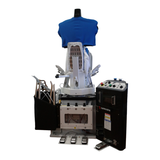
Parts Name Main device Body Front Clamp Side Expander Side Clamp Operation Button Rotation Lever (Manual) Control Panel Control Box Multi function Foot Pedal Body up Foot Pedal Body down Foot Pedal Solenoid Valve Box Shoulder Expander Foot Pedal Center Vents Clamp Side Vents Clamp Sleever Steam Gauge... -
Page 12: Control Box Switch Position
Control box switch position ⑧ ④ ⑥ ⑭ ① ⑤ ② ③ ⑦ ⑨ ⑩ ⑬ ⑫ ⑪ ① Power Switch The switch is for the main power. Black Button is for turning the Power ON. Red Button is for turning the Power OFF. ②... - Page 13 ⑦ Blower Power Dial By turning this dial, you can change the blower power. Turn the dial clockwise and the power will go up. Turn the dial counterclockwise and the power will go down. ⑧ Body Rotation Button This button makes the body rotate automatically. ⑨...
-
Page 14: Control Panel
Control Panel ⑨ ① ② ③ ④ ⑤ ⑥ ⑧ ⑦ ① Steam Timer Button (The light turns green when the button is ON.) When this button is turned on, you can change the steam injection time with the ⑧”Dial”. ②... -
Page 15: Foot Pedal
Foot pedal ① Shoulder Expander Foot Pedal When you press this pedal, Shoulder area will expand and you can adjust clothes. Shoulder size returns when you press again. ② Body Down Foot Pedal When you keep on pressing this pedal, body will move down. ③... -
Page 16: Operation Procedures
Operation Procedures Follow the procedure for proper operation. CAUTION Improper operation can cause mechanical failure or injury to operators. Provide Air ④ ③ ② Check whether air pressure is set at the required level for main regulator and other regulators as below. -
Page 17: Provide Steam
Provide Steam Check whether steam with the pressure at 0.5MPa or more can be supplied to the machine. If the steam pressure does not reach the required level, it may adversely affect the garment finishing quality. Always check whether the steam pressure meets its requirement. ... -
Page 18: Set The Clothes On The Body
・Make sure there is no one working near the machine before beginning operation. CAUTION ・Beware of pinching hands or garment by moving part during the operation. Rotation Button (Auto) Set the clothes on the body ≪In case of finishing center vents/side vents≫ (1)... - Page 19 (6) Turn the body to the front side by using the rotation button (auto), or rotation lever (manual) (Please see the page 18 Figure-1.) (7) Press the shoulder expander foot pedal. →Expander will expand according to garments shoulder line. Straighten shoulder line if it is needed. Shoulder Expander Foot Pedal Multi Function Foot Pedal Figure-5...
- Page 20 ≪ ≫ In case of the jumper finishing (1) Turn the body back with the rotation button (auto) or rotation lever (manual) (It makes setting the garment easier.) Mode Selection Switch (2) Change the Mode Selection Switch to the “Jumper Mode”. (3)...
-
Page 21: Turn The Power Off
Turn the power off. Turn the power OFF by pushing the red button at right side of the Control Box. →The power lamp will be turned off. *When switching back on, make sure there is nothing displayed. Other Operations How to Reset Emergency Stop When the Emergency Stop Button is pushed, “E1”... -
Page 22: Cover/Pad Change Instruction
Turn the power off before doing this operation. For optimal performance use a factory original cover made only by Sankosha. Using another company’s cover may give a bad finish. Sankosha takes no responsibility if you do not use factory original covers & padding. -
Page 23: Upper Body Cover Setting
2. Upper Body Cover setting Upper Body Cover ① Put Upper Body Cover on the body so that the Steam Cover is in the front position. ② Pass the string which is attached inside of the Steam Cover through the hole of body from outside and tie it in the body. -
Page 24: Test Operation
Test Operation Before using the test operation, make sure there is no one working WARNING near the machine. The Test mode operation enables the machine to run each process while the machine runs all the functions continuously on the normal operation. Operation Procedures Step 1: Push the "Test"... -
Page 25: Test Number List
Test Number List Test No. Test Item Remarks Steam Injection Solenoid (No.1) o 0 1 ・It will work 0.3 seconds when steam button is ON. ・ Buzzer sounds 1.0 second later when Center Vents Clamp Center Vents Clamp Solenoid closes. Buzzer sounds 0.7 seconds later when it opens. o 0 2 (No.2) Adjust the speed to the beep. -
Page 26: Service Menu
Service Menu It is extremely dangerous in Control Box. WARNING Do not touch anywhere unless otherwise specified. Push the Service Button (BP1) on the main circuit board in the control box; you can check the “Input Test”, “Output Test”, “Volume Setting”, “Dip Setting” and “Timer Setting”. Furthermore, you can reset all the settings to factory initial setting and check the software version. - Page 27 Service Menu List (Please see “Service Menu Explanation” for further details.) ■ Display Displayed word Function Input test 1 is operated. Input test 2 is operated. Output test is operated. Each volume setting. Dip function setting. Time setting displayed in display window. Initialization of volume setting is operated.
- Page 28 Chart-1 “Input Test 1” List (continue from the previous page) Input Button/Sensor Name Input Button/Sensor Name Shoulder Expander Foot Pedal Wide Side Vents Selection Switch S 1 S 8 Body Down Foot Pedal S 2 Side Clamp Selection Switch S 9 Body Up Foot Pedal S...
- Page 29 4. VoL (Volume Setting) ・Display by Operation Procedure 1 and 2. Push ④ the “Enter Button” to select. ・ Turn ⑤ “Dial”. Select the number (Chart-3) you want to change, then push ④ the “Enter Button”. The timer of the selected Volume Setting shows up. ・...
- Page 30 6. tou (Timer Setting) by Operation Procedure 1 and 2. Push ④ the “Enter Button” to select. ・Display ・ Turn ⑤ the “Dial”. Select the number (Chart-5) you want to change, then push ④ the “Enter Button”. The selected timer shows up. ・...
-
Page 31: Trouble Shooting
◎ During the operation, an error number shows up at the Display Window on the Operation Panel if something is wrong. Check below List, and take the necessary action. Call your dealer or Sankosha if the normal operation does not resume. It is extremely dangerous in Control Box. - Page 32 1.Error Item Error No. 2.Error Description 3.Check Point 1.Rotation Start Overtime Error .Middle sensor (SQ02) is not detected after more than 4sec. From body rotation start. 3.(1) If the red light of the sensor does not turn on when you put a magnet over the rotation middle sensor, the sensor is in error.
- Page 33 1.Error Item Error No. 2.Error Description 3.Check Point 1 Rotation Button Error 2. Steam Button stays activated if the button is staying pushed by something when the main power is ON, or the machine is at the original position. 3.(1) In the case of keep pushing the button, please release the button. Also, please remove anything which is pushing the button.
- Page 34 Please check whether the switch is broken or a wire connection is loose or disconnected. 1. 24V Error 2. The abnormalities of the emergency stop circuit of a substrate. 3. The error will be released when you push the Reset button. When occurring many times, call your dealer or Sankosha...
-
Page 35: Daily Maintenance
Use “Item Check List” for checking the correct service procedures. If at any time you have any questions, please do not hesitate to contact your Sankosha dealer or us. Check Item List... -
Page 36: Check Item (Daily)
Check Item (Daily) (1-4) (1-3) (1-2) Air Pressure: Figure-1 Check whether air pressure is set at the required level for main regulator and other regulators. (1-1) Main Regulator ・・・0.5MPa (1-2) Body Rotation Cylinder ・・・0.3MPa (1-3) Side Expander Cylinder ・・・0.2MPa (1-4) Shoulder Expander Cylinder ・・・0.2MPa Body Up/Down Cylinder (1-1) [How to Adjust Pressure]... - Page 37 Steam Pressure: Figure-3 Steam Pressure Gauge Check the steam pressure gauges (0.5MPa). (0.5MPa) ※ If the steam pressure does not reach the Cock required level, it may adversely affect the garment finishing quality. Steam trap check: Figure-3 Check to see if the Steam Trap works properly. If not, it may malfunction.
-
Page 38: Check Item (Annual)
Blower filter check: Figure-5 Check to make sure the Blower Filter is not clogged by any dirt and dust. If so, clean immediately. If you keep using the filter without cleaning, this can cause poor finishing quality as well as a decrease in the blower power. -
Page 39: Maintenance Check List
Maintenance Check List Check Item (Daily) Item Air Pressure Regulator Steam Pressure Steam Trap Cover Emergency stop Blower filter Item Air Pressure Regulator Steam Pressure Steam Trap Cover Emergency stop Blower filter Check Item (Annual) Item Regulator filter Photocopy this checklist for ongoing maintenance... -
Page 41: Spare Parts List
Spare Parts List Index 1: Front Diagram 2: Rear Diagram 3: Switch/Solenoid Valve Diagram 4: Steam Piping Diagram 5: Cover Diagram... -
Page 42: Front Diagram
1 :Front Diagram REV:3 Front Diagram... - Page 43 Front Diagram REV:3 Part Name Part number Q'ty Remark 101 BODY FRP Q0D210 102 Shoulder (Right) FRP Q0D211 103 Shoulder (left) FRP Q0D212 Cylinder B1C003 Front Clamp Cylinder packing set B6H012 105 Speed Controller C1A002 106 Knuckle Joint B6B001 Cylinder B1C006 Side Expander Cylinder packing set...
-
Page 44: Rear Diagram
2 :Rear Diagram REV:3 Rear Diagram... - Page 45 Rear Diagram REV:3 Part Name Part number Q'ty Remark 201 Cylinder B1L004 Shoulder Expander Joint C0B010 203 Knuckle Joint B6A007 Cylinder B1C011 Center Vents Clamp Cylinder packing set B6H012 205 Speed Controller C1A002 Knuckle Joint B6B001 Cylinder B1A016 Wide Side Vents Cylinder packing set B6H017 Cylinder...
-
Page 46: Switch/Solenoid Valve Diagram
3 : Switch/Solenoid Valve Diagram REV:3 Switch/Solenoid Valve Diagram... - Page 47 Switch/Solenoid Valve Diagram REV:3 Part Name Part Number Q'ty Remark 301 Breaker Switch 21C007 302 Push Button Switch 21I151 Emergency Push Button Switch 21I111 Reset Push button cap 21I044 304 Push Button Switch 21I168 Rotation 305 Push Button Switch 21I166 Blower 306 Push Button Switch 21I090...
-
Page 48: Switch/Solenoid Valve Diagram
3 : Switch/Solenoid Valve Diagram REV:3 Switch/Solenoid Valve Diagram... - Page 49 Switch/Solenoid Valve Diagram REV:3 Part Name Part number Q'ty Remark 324 Manifold valve A0F154 Valve A0E012 No.1:Open Steam No.2: Valve A0E012 Close Center Vents Clamp Valve A0E012 No.3:Close Front Clamp No.4:Open Side Valve A0E018 Expander No.5:Close Side Valve A0E012 No.6:Close Side Clamp Valve A0E012 No.9:Wide Side Vents Clamp...
-
Page 50: Steam Piping Diagram
4 :Steam Piping Diagram REV:3 Steam Piping Diagram... - Page 51 Steam Piping REV:3 Part Name Part Number Q'ty Remark 401 Air Muffler J0A001 402 Piston Valve A0G003 403 Joint C0E001 404 Steam Gauge J0A003 405 Y Type Strainer J2M007 406 Steam trap J2N001 407 Radiator RD180-000...
-
Page 52: Cover Diagram
5: Cover Diagram REV:3 Cover Diagram... - Page 53 Cover Diagram REV:3 Part Name Part Number Q'ty Remark 501 Upper Body Cover S1D549 502 Lower Body Cover S1D550 503 Wire Fillet Rear Clamp Cover S1D059 504 Rear Clamp Mat S1D051 505 Wire Fillet Front Clamp Cover S1D058 506 Front Clamp Mat S1D035 507 Wire Fillet Side Clamp Cover S1D060...
-
Page 54: Attached Diagram
Attached Diagram Sensor Diagram Electric Connection Diagram 1/4~4/4 Steam Piping Diagram Air Connection Diagram... - Page 55 Sensor(Operation Button) Diagram SB02: Reset Button SB03: Body Rotation Button SB04: Blower Button SW03: Wide Side Vents Select Switch SB05: Steam Button SW01: Mode Select Switch SB01: Emergency Button VR01: Blower Power Dial (Operation Button) SW04: Stretch Select Switch SW05: Stretch Select Switch SW02: Timer Select Switch SB06: Auto Start Button SQ01: Body Rotation End Sensor...
- Page 60 Steam Piping Diagram ④ ② ③ ① ⑤ ⑥ ① Radiator : RD180-000 ② Piston Valve : D290A399 ③ Pressure Gauge : AMT7/16 60φ 1.6MPa ④ Steel Muffler : SBN-38 ⑤ Y Strainer : FC KY-4G4 15A 100Mesh ⑥ Steam Trap : YH-15A...
- Page 62 DF-100E-V3 Rev.6 2019. 1...
Need help?
Do you have a question about the DF-100E-V3 and is the answer not in the manual?
Questions and answers