
Related Manuals for Terex FUCHS MHL340 D


Summary of Contents for Terex FUCHS MHL340 D
- Page 1 12.65 Service Manual MHL340 D Installation Generator with wiring Serial No. 340210 / 1350 > Year of Construction 2006 > Edition 15.08.08 en (englisch)
-
Page 3: Table Of Contents
Contents General............................3 Purpose............................ 3 Contents........................... 3 Target group ..........................3 Entire documentation ....................... 3 In case of questions ......................... 3 Safety ............................4 Requirements for service personnel ..................4 General safety notes for service work..................5 Special instructions ........................6 Information for installation ..................... - Page 4 Contents Tightening torques for screw connections................59 Measuring instrument for V-belt tension................. 59 Index............................60 2 (60) Version 11.08.2008 12.65-SA10403-en-110808...
-
Page 5: General
The Operating Instructions and the instructions on the service In your interest, TEREX | Fuchs continues work to be carried out must be developing the products further. For this read and understood before reason, we reserve the right to implement beginning with the work. -
Page 6: Safety
Must be able to read and understand circuit diagrams and hydraulic diagrams. Must have attended a work-specific training organized by TEREX | Fuchs or a person authorized by TEREX | Fuchs for carrying out the required service work. 4 (60) Version 11.08.2008... -
Page 7: General Safety Notes For Service Work
2 Safety General safety notes for service work Increased danger of injury Safe handling of the machine Service work always involves a high danger Safety-aware behavior before, during and potential. Serious and permanent injuries after service work is of vital importance. The may occur, which might, under extreme cir- following notes are examples only and not cumstances, even result in death. -
Page 8: Special Instructions
2 Safety Special instructions Safety instructions Used symbols Safety instructions that refer to a described Symbol Description action are indicated at the beginning of such action or sequence of actions. They explain a General warning of a danger area danger and how to avoid it in brief. Their for- or dangerous situation. - Page 9 2 Safety Danger for body parts by cutting or separating. Danger that objects might be pulled into machine parts. Danger because of automatic start. Danger because of poisonous substances. Danger because of corrosive sub- stances. Ecologically harmful substances. Wear ear and eye protection. Read safety-relevant information.
-
Page 10: Information For Installation
3 Information for installation Information for installation Assembly overview and working time The following data are based on experiences. They might differ depending on the local situation. Staff Duration Modifications 10 hours Parts included with delivery are assembled. No additional conversions are required. -
Page 11: Lifting Equipment And Devices
3 Information for installation Lifting equipment and devices Safety j WARNING j WARNING Risk of bruising when using Risk of bruising due to incorrect lifting equipment incorrect storage places • Observe component weight. • Secure components lowered • Consider auxiliary materials, for down against toppling over. -
Page 12: Special Tools And Aids
3 Information for installation Special tools and aids Designation Units Remark Standard equipment Long ruler (about 1250 mm) on page 26 on page 26 Short ruler (about 600 mm) Measuring instrument for V-belt tension on page 59 Loctite 572 on page 39 Silicon cartridge with syringe (with "Quick on page 54 Connect"... -
Page 13: Definition Of Views
3 Information for installation Definition of views The descriptions include depictions of the work steps. For orientation purposes, the caption of the pictures indicates the viewpoint of the viewer. The following designations are used: 340-1560-12.65-59 340-1560-12.65-63 Starter side Fan side 340-1560-12.65-52 Service ladder 340-1560-12.65-85... -
Page 14: Preparations
4 Preparations Preparations Placing the machine in service position Unload machine and place it in an even place that is protected against weather in- fluences and offers sufficient work area. Align the uppercarriage parallel to the un- dercarriage. Lower the dipperstick (1) with the loading equipment and the 4-point outrigger (2) down to the ground. -
Page 15: Switching Off And Securing The Machine
4 Preparations Switching off and securing the machine n DANGER Electrical shock causing death • Do not perform any assembly work while the machine is run- ning. • Do not insert the magnet cable into the generator until the cou- pler socket is connected. -
Page 16: Installation Of Generator
5 Installation of generator Installation of generator Structure of the description The installation of the generator is described If machine parts must be removed or in- step by step. The steps are summarized in stalled, the process is described step by step. groups for purposes of clarity. - Page 17 5 Installation of generator Remove the engine cover (1). 340-1560-12.65-44 Engine cover (view: starter side) Loosen the fastenings (2) and remove the cover plate (1). 340-1560-12.65-61 Cover plate (view: service ladder; underneath) Notes on closing the accesses On principle, close the accesses in reverse sequence.
-
Page 18: Cleaning The Assembly Area
5 Installation of generator Cleaning the assembly area j WARNING NOTICE When cleaning with a high-pressure cleaner, Danger of injury to the eyes never direct the jet onto electric components from liquid jet and scattering and connections or the cooler fins. dirt •... - Page 19 5 Installation of generator In the engine compartment, clean the fas- tening and support for the air conditioning compressor (1) and the area around the V- belt pulley (2) on the engine. 340-1560-12.65-20 Components in the engine compartment to be cleaned (view: fan side;...
-
Page 20: Preparing The Generator
5 Installation of generator Preparing the generator Have these parts ready: 1) V-belts 2) Tensioning pulley support with fastening (screws M10×30 mm; D internal of disk = 10.5 mm) 3) Belt tensioners with fastening (screws M10×30 mm; D internal of disk = 10.5 4) V-belt pulley for generator with clamping chuck 5) V-belt pulley for engine... -
Page 21: Installing The Generator
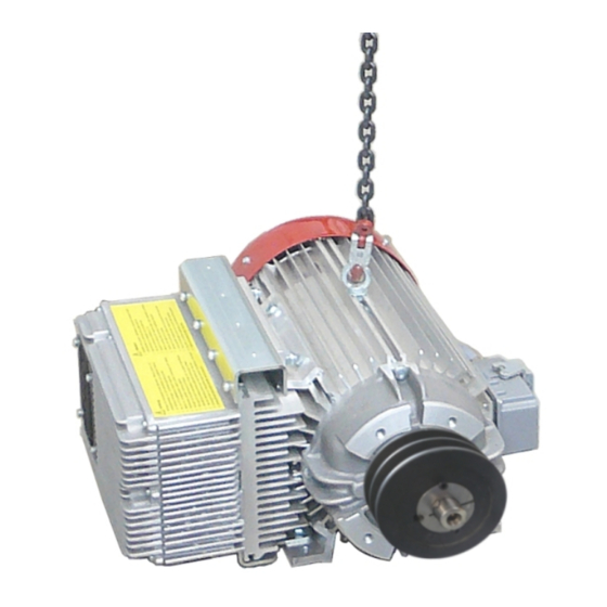
5 Installation of generator Installing the generator Raising the generator j WARNING Risk of crushing by falling generator • Only use lifting equipment that is suitable for the weight (for information on the lifting equipment, refer to on page 9). •... - Page 22 5 Installation of generator Installing the V-belt pulley Clean and degrease all joining points of the V-belt pulley (1), clamping chuck (2), and shaft journal (3). Coat the bolts (4) with a thin film of oil. Place the clamping chuck (2) in the V-belt pulley (1) and screw in the bolts (4) lightly.
- Page 23 5 Installation of generator Inserting the generator j WARNING Risk of crushing by falling generator • Only use industrial trucks that are suitable for the weight (for information on the lifting equipment, refer to on page 9). • Do not remain under or put your hands beneath the generator when it is raised.
-
Page 24: V-Belt Installation
5 Installation of generator V-belt installation Replacing the V-belt pulley Loosen the lower fastening (2) on the air conditioning compressor (1). 340-1560-12.65-14 Loosening the air conditioning compressor (view: fan side) Loosen fastenings (1) and (3) on the sup- port (4) as well. Swivel the air conditioning compressor against the engine so that the tension on the V-belt (2) is released. - Page 25 5 Installation of generator Fasten the new V-belt pulley (1). Torque: 125 Nm. Set the V-belt in place on the rear diame- ter of the V-belt pulley (2) and on the air conditioning compressor (3). Tension the V-belt and fasten the air con- ditioning compressor in place again.
- Page 26 5 Installation of generator Mounting the lower belt tensioner Check the mountery surfaces for even- ness and clean them. Fasten the tensioning pulley support (1) loosely. Make certain the washer (2) is not resting on the welding seam. 340-1560-12.65-25 Mounting the lower tensioning pulley support (view: fan side; right) Remove the belt tensioner of the fastening screw (1).
- Page 27 5 Installation of generator Attaching the shielding plate Apply clamp (4) (only for 13 kW generator). Insert the sealing profile (3) on the shielding plate (1). Set the shielding plate on the generator plate (2). 340-1560-12.65-37 Attaching the shielding plate (attached outside the machine) Align the shielding plate with the fastening holes (1).
- Page 28 5 Installation of generator Setting the V-belts in place Set the V-belt in place on the V-belt pulleys of the engine (1) and generator (2). 340-1560-12.65-22 Setting the V-belt in place (view: fan side); shielding plate is not shown for reasons of clarity. Aligning the upper tensioning pulley and tightening the bolts Swivel the upper tensioning pulley in onto...
- Page 29 5 Installation of generator Provisionally tightening the upper belt tensioner Swivel the upper belt tensioner until the scale (1) is opposite the 15° mark on the corner (2). Tighten the fastening screw (3). Torque: 86 Nm. 340-1560-12.65-29 Provisionally tightening the upper belt tensioner (view: fan side;...
- Page 30 5 Installation of generator Placing the lower tensioning pulley Swivel the lower belt tensioner (1) until the tensioning pulley is resting lightly against the belt. Normally, two fingers one laid over the other will then fit between the two tensioning pulley (2). 340-1560-12.65-09 Placing the lower belt tensioner (view: fan side;...
-
Page 31: Installing And Connecting The Electrical Box And Rocker Switch
5 Installation of generator Installing and connecting the electrical box and rocker switch Have these parts ready: 1) Connecting cable 2) Electrical box and support 3) Rocker switch 4) Corrugated hose holder 5) Screws 6) Cover for corrugated hose holder 340-1560-12.65-91 Parts required for electrical box Installing the rocker switch in the operator... - Page 32 5 Installation of generator Remove the two lower fastening screws (3) on the right control lever carrier (1). Connect and tighten the support (2) with these fastening screws. 340-1560-12.65-93 Electrical box on the control lever carrier (view: driver's seat; right) Laying connecting cable for electrical box/generator Set down the connecting cable on the...
- Page 33 5 Installation of generator Remove the cover (1) on the right control lever carrier. Pull out the B55 connection cable (2). 340-1560-12.65-96 Connection cable on the control lever carrier (view: driver's seat; right) Guide in the connecting cable (2) from the access hole (1) into the control lever car- rier (3).
- Page 34 5 Installation of generator Guide the connection cable (3) out through the access hole (4) as well. Insert the connecting cable plug (3) into the electrical box (1) and tighten it (2). 340-1560-12.65-97 Connecting the connection cable (view: driver's seat; right) Guide the connecting cable (1) over the lever arm.
- Page 35 5 Installation of generator Guide the connection cable (1) down from the lever arm and to the right to the fasten- ing console (3). Fasten in place later with corrugated hose holders (2). Guide it down and fasten with corrugated hose holder (4) on the fastening console.
- Page 36 5 Installation of generator Guide the connection cable (1) under the service ladder in the direction of the gen- erator (3). Fasten in place later with corrugated hose holder (2). 340-1560-12.65-32 Laying the connecting cable to the generator (view: service ladder;...
-
Page 37: Attaching And Connecting The Coupler Socket
5 Installation of generator Attaching and connecting the coupler socket Have these parts ready: 1) Magnet cable 2) Coupler socket with screws 3) Harting connector 4) Corrugated hose holders 5) Cable screw connection 6) Screws for corrugated hose holders 7) Plug inserts 8) Cover for corrugated hose holders 340-1560-12.65-99 9) Cable ties... - Page 38 5 Installation of generator Open the hose bracket (4) enough to push the magnet cable through. Guide the magnet cable (1) onto the boom. Fasten the magnet cable onto the connec- tion bar later with the corrugated hose holder (2) and onto the hydraulic hose (3) with cable ties.
- Page 39 5 Installation of generator Slightly open the hose bracket (2). Lay the magnet cable (1) further to the center on the dipperstick (3). Fasten the magnet cable on the hydraulic hose with cable ties (4) later. Close the hose bracket later. 340-1560-12.65-XX 340-1560-12.65-70 Magnet cable on dipperstick (front view)
- Page 40 5 Installation of generator Guide the magnet cable (1) out of the dip- perstick (2). After the attachment of the coupler socket (3) described on the following pages is complete, close all hose brackets and fas- ten the magnet cable with cable ties. 340-1560-12.65-101 Magnet cable to the coupler socket (front view) 38 (60)
- Page 41 5 Installation of generator Attaching the coupler socket Depending on the generator type/connection cable, the cable connection (2) built into the coupler socket (1) may have to be converted. If conversion is required: Remove the cable connection (2). Coat the threading of the reducer (5) with Loctite 572 (3) and screw it in.
- Page 42 5 Installation of generator To tighten the cable ends: (1): Yellow/Green (2): Black and gray (3): Brown and blue 340-1560-12.65-105 Assignment of cable ends Retighten the cover cap (1). Retighten the swivel nut (2). 340-1560-12.65-106 Attached coupler socket 40 (60) Version 11.08.2008 12.65-SA10403-en-110808...
- Page 43 5 Installation of generator Laying the magnet cable from the boom to the generator Guide the cable end (1) down between the connection bar (2) and swivel motor (3). 340-1560-12.65-50 Lay the magnet cable from the boom down (view: service ladder;...
- Page 44 5 Installation of generator Guide the magnet cable coming out of the access hole (1) along under the service ladder (2). 340-1560-12.65-45 Magnet cable coming out of the access hole Guide the magnet cable (1) along under the service ladder. Fasten in place with corrugated hose holders (2) later.
- Page 45 5 Installation of generator Guide the magnet cable (1) out of the opening (2) in the uppercarriage to as- semble the Harting connector. 340-1560-12.65-42 Guiding the magnet cable out 12.65-SA10403-en-110808 Version 11.08.2008 43 (60)
- Page 46 5 Installation of generator Installing the Harting connector Screw the cable screw connection (1) into the plug housing (2). Push the plug inserts (3) into the support (4). Loosen the swivel nut on the cable con- nection (1) and push it over the magnet cable.
- Page 47 5 Installation of generator Fasten the support (2) in the plug housing (1) with the fastening screws (3). Tighten the swivel nut (4). 340-1560-12.65-110 Assembled Harting connector Inserting the Harting connector n DANGER Electrical shock causing death • Do not insert the magnet cable until the coupler socket has al- ready been connected.
-
Page 48: Inserting The Air Hose (13 Kw Generator Only)
5 Installation of generator Checking the magnet cable Check to make certain machine move- ments could not cause the magnet cable to come under tension or be squeezed. Check whether all hose brackets are closed and the magnet cable is adequately fastened with cable ties. -
Page 49: Variations For Multi-Purpose Stick (Option)
5 Installation of generator 5.10 Variations for multi-purpose stick (option) Laying the magnet cable over the boom to the coupler socket Cable routing varies somewhat for machines with an optional multi-purpose stick. Connect the magnet cable to the genera- tor as described for standard machine and lay it to the boom. - Page 50 5 Installation of generator Slightly open all hose brackets (2). Lay the magnet cable (1) over the boom to the dipperstick. At the transition to the dipperstick, guide the magnet cable to the center of the stick (4). Fasten the magnet cable on the hydraulic hose and the line with cable ties (3) later.
- Page 51 5 Installation of generator Guide the magnet cable (1) to the coupler socket (2). After the coupler socket (2) is connected, close all hose brackets and fasten the magnet cable with cable ties. 340-1560-12.65-XX 340-1560-12.65-74 Magnet cable to the coupler socket (front view) 12.65-SA10403-en-110808 Version 11.08.2008 49 (60)
-
Page 52: Deviations For "Quick Connect" Equipment
5 Installation of generator 5.11 Deviations for "Quick Connect" equipment For machines with optional "Quick Connect" equipment, a magnet plug and magnet socket must be attached and connected at the coupling point. Have these parts ready: 1) Magnet cable for generator 2) Magnet cable for coupler socket 3) Magnet socket with small parts 4) Magnet plug with small parts... - Page 53 5 Installation of generator Open the hose bracket (5) enough to push the magnet cable through. Guide the magnet cable (1) under the safety filters (3). Fasten the magnet cable onto the hose bracket later with a clamp (2) and onto the hydraulic hose (4) with cable ties.
- Page 54 5 Installation of generator Open the hose brackets slightly (3) - (4) and lay the magnet cable (1) to the stick base. Fasten the magnet cable onto the hydrau- lic hose later with cable ties (4). Close the hose brackets later. 340-1560-12.65-XX 340-1560-12.65-80 Magnet cable to the stick base (view: service ladder;...
- Page 55 5 Installation of generator Lead the magnet cable (1) out of the open- ing to the hydraulic cylinder unit (2). After the magnet socket is connected, close all hose brackets and fasten the magnet cable with cable ties. 340-1560-12.65-113 Magnet cable to the hydraulic cylinder unit (front view) Preparations for the magnet socket The illustration shows the parts for the mag- net socket.
- Page 56 5 Installation of generator Insert the contacts (2) into the housing (1): (3): Brown and blue (4): Yellow/Green (5): Black and gray Press the cable with sealing ring (6) into the profile in the housing designed for that purpose. Apply silicon to the connection points of the housing and around the contacts (7).
- Page 57 5 Installation of generator Laying the magnet cable from the magnet socket to the coupler socket Lay the magnet cable (2) in the stick head (1) under the hose bracket (3). Guide the magnet cable through the open- ing out of the stick head (4). 340-1560-12.65-116 Magnet cable to stick head Attaching the magnet plug...
- Page 58 5 Installation of generator Attaching the coupling plug Wrap the cable end from the coupler sock- et to the stick head with coil (2). Attach the coupler socket as described for the standard version. h on page 39: Attaching the coupler socket Equalize the cable length with a loop un- der the cover (3).
-
Page 59: Configuring The Electronics
5 Installation of generator 5.12 Configuring the electronics The enable code is indicated with the scope of parts delivered. Enable the option. h More information: Service documenta- tion 340-1560-12.65-119 Entering the enable code 12.65-SA10403-en-110808 Version 11.08.2008 57 (60) -
Page 60: Commissioning
6 Commissioning Commissioning Checks before switching on WARNING! Unpredictable movements are possible. n DANGER Increase the load incrementally. After 30 minutes, switch off the engine and Danger of fatal injuries – electri- cal shock allow it to cool off. • Have the electrical functioning Bring the machine to a safe state. -
Page 61: Appendix
7 Appendix Appendix Technical data Designation Weight [kg] Remark Generator 13 kW / 20 kW approx. 130 kg Tightening torques for screw connections NOTICE Tightening torques TM [Nm] The specified tightening torques apply for 10.9 12.9 screwed connections for which no values have been indicated in the Service Instructions, Op- M 4 x 0.7 erating Instructions or the documentation of the... - Page 62 8 Index Index References to service documentation Enabling options References to the operating instructions V-belt tension, air conditioning compressor 23 60 (60) Version 11.08.2008 12.65-SA10403-en-110808...
- Page 64 Hauptverwaltung / Verkauf / Kundendienst Head Office / Sales / After Sales Service Sièges Administratif / Vente / Service Après-Vente Terex Deutschland GmbH Geschäftsbereich Terex Fuchs 76669 Bad Schönborn GERMANY Fon.: ++49 (0) 72 53 / 84-0 Fax: ++49 (0) 72 53 / 84 411 E-Mail: Info@fuchs-terex.de...
Need help?
Do you have a question about the FUCHS MHL340 D and is the answer not in the manual?
Questions and answers