
Summary of Contents for DL Manufacturing Smart Chock SC0650
- Page 1 Smart Chock™ Models SC0650 thru SC0654 A Product of 340 Gateway Park Drive North Syracuse, NY 13212 Phone: 315-463-7348 Toll Free: 866-235-7468 Fax: 315-463-8559 Email: sales@dlmanufacturing.com www.dlmanufacturing.com SCM008 - REV H 01/24/2020...
-
Page 2: Electrical Ratings
Smart Chock™ Installation Guide INTRODUCTION This manual is used for models SC650 through SC654 Series Smart Chock™ model types. Be sure to check your smart chock model type before consulting or servicing. The control board is programmed for each model’s function. The description explains the differenced between model types. - Page 3 Smart Chock™ Installation Guide Smart Chock™ ---Sequence of Operations--- Testing POWER ON – Smart Chock enters a startup routine that turns the LED’s and Relays on and off a few times. The startup routine runs for approximately 20 Seconds. Loading Dock Door is Closed, Wheel is Unchocked •...
- Page 4 INSIDE TO OUTSIDE BOX WIRING DIAGRAM J15 & J16 MODEL 650 SYSTEM WIRING DIAGRAM 651 SYSTEM WIRING DIAGRAM 652 SYSTEM WIRING DIAGRAM 653 SYSTEM WIRING DIAGRAM 654 SYSTEM WIRING DIAGRAM OUTSIDE LIGHT BOX / CHOCK WIRING DIAGRAM DL MANUFACTURING TERMS/CONDITIONS/WARRANTY 24 01/24/2020 SCM008 - REV H...
- Page 5 7 conductor 18 gauge ½” flexible conduit with Inside Box wire connector for 7/8 knockout Field Notes: FOR SERVICE ASSISTANCE CALL DL MANUFACTURING TOLL FREE 866-235-7468 Smart Chock Model #:___________________________________________ Smart Chock Serial #: (LOCATED LOWER PORTION OF CONTROL BOARD)_______________________________________________________ Door Location...
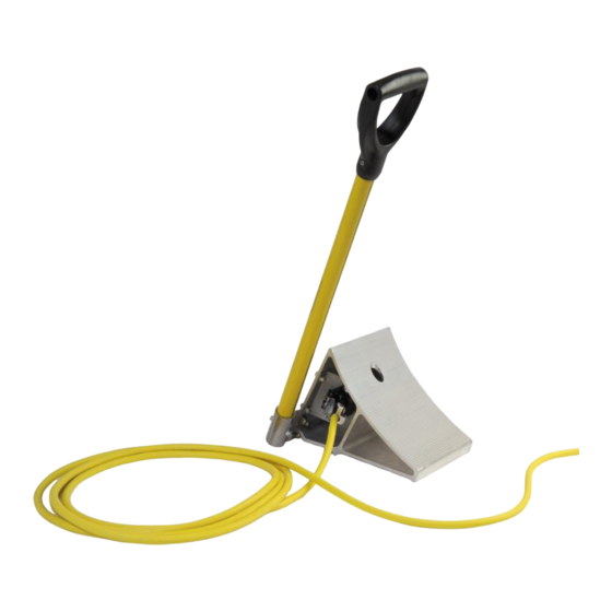
- Page 6 Smart Chock™ Installation Guide OPTION 1: STANDARD CHOCK HANDLE MOUNTING INSTRUCTIONS 1. Remove the Nuts and Bolts from the Handle Assembly. 2. Attach the Handle Assembly to the Chock as shown below using the Hardware from Step 1. Hardware & Handle orientation - Parts removed for clarity Chock after assembly FOR CHOCKS WITH YELLOW CABLES- BE SURE CONNECTION...
- Page 7 Smart Chock™ Installation Guide OPTION 2: VECTOR CHOCK HANDLE MOUNTING INSTRUCTIONS 1) Remove the Nuts and Bolts from the Extractor Assembly and Insert Extractor into Chock (Figure A.) 2) Slide Handle over Extractor. Place Washer, Lock Nut, & Bolt in that Order as Shown (Figure A.). Tighten Bolt with Torque Wrench to 96 lb-ft.
- Page 8 Smart Chock™ Installation Guide SMART CHOCK INSTALLATION WALL MOUNTED STYLE INTERNAL (YELLOW BOX) 8.0” NOTE: [203.18] Install internal Smart Chock measuring 66” from the dock floor to the top of the yellow box. Use (4) ¼” x 1¼” Tapcons 6.5” [1676.4] 6.0”...
- Page 9 Smart Chock™ Installation Guide Smart Chock- Mounting (on concrete wall or block wall) Smart Chock ™ (Black-outside box) Smart Chock ™ (Yellow-Inside box) SECTIOB B-B SCALE 1:12 CENTER OF TOP RED LIGHT SHOULD BE CONDUIT 90” ABOVE GROUND SEE PAGE 4 FOR FASTENER USAGE LEVEL 66.0”...
- Page 10 Smart Chock™ Installation Guide BOLLARD BRACKET PART # MK5027 BOLLARD BRACKET Used on bollards 4 to 10 inch diameter. 66” (2) Hose clamps & 12 ¼-20 mounting [1675.73] Bolts are included. From The floor BOLLARD BRACKET (mounting hardware Contact included) Floor Factory Line...
- Page 11 Smart Chock™ Installation Guide PHOTO EYE INSTALL - TYPICAL & MxV DOORS 01/24/2020 SCM008 - REV H...
- Page 12 Smart Chock™ Installation Guide MAGNETIC CONTACT INSTALL - ROLLING STEEL DOORS 01/24/2020 SCM008 - REV H...
- Page 13 Smart Chock™ Installation Guide INSTALLATION OF OUTSIDE COMPONENTS BOX MUST BE SECURELY FASTENED TO 7.0” See Page 7 for WALL SO WHEN CABLE IS PULLED, IT SNAPS Mounting Instructions. [177.8] OUT OF SOCKET BEFORE BOX IS PULLED OFF THE WALL. Pole Attachment RED LED LIGHT 21 9/16”...
- Page 14 REMOVE POWER Smart Chock™ Installation Guide BEFORE SERVICING. MUST BE INSTALLED BY QUALIFIED ELECTRICIAN OPTIONAL TERMINAL BLOCK JUMPERS FOR OPT2 & OPT 3 MODEL 654 LEVELER BUTTON Refer to Instructions that come with Replacement PC Boards J3-3 OR J4-3, COMMON GND DO NOT APPLY J3-2 OR J4-2, INPUT SIGNAL VOLTAGE TO J6...
-
Page 15: Incoming Power
Smart Chock™ Installation Guide SMART CHOCK FIELD WIRING DIAGRAM ™ INCOMING POWER INTERNAL (YELLOW BOX) BLACK (120 VAC, 12 A MAX, 60Hz) GND WIRE FROM CHASSIS GND IS PRE-INSTALLED ON WHITE (120 VAC NEUTRAL) MODELS 653 & 654 GREEN (GND) - ALL MODELS EXCEPT 653 &... -
Page 16: Wiring Diagram
Smart Chock™ Installation Guide SMART CHOCK FIELD WIRING DIAGRAM MODEL 654 LEVELER CONTROL SIGNAL FX LEVELER BUTTON J6-1, 8.2 VDC, 3mA MAX DO NOT APPLY ANY EXTERNAL VOLTAGE TO J6 TERMINALS J6-2, COMMON GND ON MODEL 654 SMART CHOCKS – WHEN THE LEVELER BUTTON IS PRESSED, THE FAN WILL POWER DOWN. - Page 17 Smart Chock™ Installation Guide SMART CHOCK FIELD WIRING DIAGRAM OUTSIDE LIGHTS OUTSIDE (BLACK BOX) CONECTIONS TO J2 INSIDE (YELLOW BOX) CONTROL OF PCB ASSEMBLY SC8863 (CHOCK ICON) BOARD CONNECTIONS BLUE BROWN -+12VDC BLACK RED – TOP RED LEDS OARNGE – CHOCK ICON OUTSIDE WHITE LPBK...
- Page 18 Smart Chock™ Installation Guide MODEL 650 WIRING DIAGRAM 01/24/2020 SCM008 - REV H...
- Page 19 Smart Chock™ Installation Guide MODEL 651 WIRING DIAGRAM 01/24/2020 SCM008 - REV H...
- Page 20 Smart Chock™ Installation Guide MODEL 652 WIRING DIAGRAM 01/24/2020 SCM008 - REV H...
- Page 21 Smart Chock™ Installation Guide MODEL 653 WIRING DIAGRAM 01/24/2020 SCM008 - REV H...
- Page 22 Smart Chock™ Installation Guide MODEL 654 WIRING DIAGRAM 01/24/2020 SCM008 - REV H...
- Page 23 Smart Chock™ Installation Guide OUTSIDE LIGHT BOX / CHOCK WIRING DIAGRAM FOR BLACK ELECTRICAL CORD =BLACK =WHITE =RED =GREEN OUTSIDE LIGHT BOX / CHOCK WIRING DIAGRAM 01/24/2020 SCM008 - REV H...
- Page 24 In no event shall DL Manufacturing be required to repair, replace or reimburse Customer for more than the part or material that is found to be defective and DL Manufacturing’s liability shall in such event be no greater than the invoiced price of the item and shall not include labor, shipping or other costs incurred in connection with the reshipment of defective Goods to DL Manufacturing or the reinstallation of such Goods after any repair or replacement.
Need help?
Do you have a question about the Smart Chock SC0650 and is the answer not in the manual?
Questions and answers