Advertisement
Quick Links
4819050/1
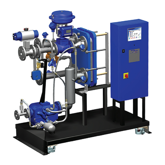
DHW Potable and Process Water Heating
Compact Heat Transfer Solution
Installation and Maintenance Instructions
IM-P481-04 CH Issue 1
Spirax EasiHeat
IM-P481-04
TM
1. Safety information
2. General
Product information
3. Installation
4. Commissioning
5. Operation
6. Maintenance
© Copyright 2012
Printed in the UK
CH Issue 1
1
Advertisement

Related Manuals for Spirax Sarco EasiHeat DHW

Summary of Contents for Spirax Sarco EasiHeat DHW
- Page 1 4819050/1 IM-P481-04 CH Issue 1 Spirax EasiHeat DHW Potable and Process Water Heating Compact Heat Transfer Solution Installation and Maintenance Instructions 1. Safety information 2. General Product information 3. Installation 4. Commissioning 5. Operation 6. Maintenance © Copyright 2012 IM-P481-04 CH Issue 1 Printed in the UK...
- Page 2 IM-P481-04 CH Issue 1...
- Page 3 1. Safety information Note: This document refers only to the mechanical installation and commissioning of the Spirax EasiHeat DHW packaged heat exchange system and should be used in conjunction with the relevant IMIs for the other system components and supplementary safety information for all the system components.
- Page 4 Determine the correct installation situation and direction of fluid flow. iv) Spirax Sarco products are not intended to withstand external stresses that may be induced by any system to which they are fitted. It is the responsibility of the installer to consider these stresses and take adequate precautions to minimise them.
- Page 5 1.9 Tools and consumables Before starting work ensure that you have suitable tools and / or consumables available. Use only genuine Spirax Sarco replacement parts. 1.10 Protective clothing Consider whether you and / or others in the vicinity require any protective clothing to protect against the hazards of, for example, chemicals, high/low temperature, radiation, noise, falling objects, and dangers to eyes and face.
- Page 6 2. General product information 2.1 General information The Spirax EasiHeat™ DHW system uses steam to provide accurate heating of potable hot water or hot water for processes. Systems can be sized for any heating duty from 50 kW to approximately 1.1 MW and are supplied fully assembled and pressure tested ready for installation.
- Page 7 2.2 Spirax EasiHeat DHW nomenclature The product nomenclature is a reflection of the core items and unit options that have been ordered and supplied – See the table below: Spirax EasiHeat DHW nomenclature example: Domestic hot water EHD = Spirax EasiHeat™ DHW 1 = DN20 2 = DN25 3 = DN32...
- Page 8 The installation of an appropriately sized safety valve, to protect any lower pressured equipment on either the hot or cold side of the plate heat exchanger, is strongly recommended. Spirax Sarco supplies a range of traps, strainers, separators, safety valves and pressure reducing equipment. 3.2 Air supply If a pneumatic control system is installed, connect a compressed air supply (4.5 to 8 bar g...
- Page 9 3.4 Electrical specifications Electrical supply: Refer to the name-plate on the unit 110 Vac / 60 Hz Control panel supply voltage 240 Vac / 50 Hz Control panel load requirements Internally fused at 5 amps 24 Vac Electrical control actuator 4 - 20 mA control Pneumatic control actuator 4 - 20 mA control...
- Page 10 Remote operation and retransmission connections Terminal designation Description Type Remote set point 4-20 mA input Remote enable 24 Vdc signal Retransmission value 4-20 mA output 001- 001+ 24.3 CHANNEL 13 REMOTE SYSTEM CHANNEL 0 4-20mA ENABLE RETRANSMISSION REMOTE PID OF PV OR VALVE Fig.
- Page 11 Terminal layout overview X1 - X5 X6 - X8 X9 - X10A X10B - 10C PT100 4 - 20 mA 4 - 20 mA actuator Bypass inputs inputs outputs signals pump X13A-C X14 - X16 Bypass High limit volt free remote valve valve...
- Page 12 4. Commissioning We recommend that you use the service and support of a Spirax Sarco commissioning engineer. Details of this service can be found by contacting Spirax Sarco. Note: Pre commissioning requirements: In most new installations, dirt collects in the steam pipeline during construction of the system.
- Page 13 Open the secondary (cold side) isolating valves downstream of the Spirax EasiHeat Start the main secondary water circulating pump(s) if fitted. Check and confirm there is secondary water circulation through the Spirax EasiHeat If the circulation is okay, switch on the main power to the control panel (local isolator). Turn the control panel isolation switch to ‘ON’.
- Page 14 TVA flowmeter commissioning chart To navigate around the first level menu use the up and down arrows, to enter any sub menu use the right arrow. Fig. 10 TVA configuration displays Normal run mode Default = 8888 Configuration but user display sequence sub-menus settable.
- Page 15 From the Basic dAtA menu navigate to OUtPUts and press the right arrow to enter the sub menu of 4 - 20 mA. 4-20 mA PUtS Fig. 11 PULSE The next menu Sorce will need FLOW to be selected. Obtain the correct flow data from the Spirax EasiHeat specification sheet supplied for accuracy, thereafter navigate down the menu and input: - Minimum flow = 4 mA...
- Page 16 4.4 HMI quick start commissioning procedure: The HMI display is a 7" touch screen, and the following procedures detail a basic set-up of the control system from initial power up. A more detailed description of each individual feature can be found in the full operation and maintenance manual. Fig.
- Page 17 The next screen (Figure 18) requires confirmation of the system to be configured. Fig. 18 Select the DHW option, the selection shall be confirmed by the icon becoming highlighted with a blue surround and a continue button shall be revealed. Press the continue button to advance to the system configuration menu.
- Page 18 The system configuration should match the mechanical configuration of the Spirax EasiHeat and control system of the plant Spirax EasiHeat plant and are detailed as follows:- Fig. 20 High limit selection Independently installed controlled controlled Fig. 21 High limit valve selection Valves Fig.
- Page 19 4.5 TVA not installed If the Spirax EasiHeat unit is not fitted with a TVA flowmeter then the system configuration is now complete and the global navigation buttons at the base of the screen can be used to navigate around the system. Fig.
- Page 20 Press the energy button to navigate to the energy set-up page (Figure 27): Fig. 27 Accurately enter the specific energy data to ensure that the valid energy data can be calculated. Boiler fuel properties - Selected via the drop down menu Boiler feedwater temperature Boiler efficiency Cost per unit of fuel...
- Page 21 4.7 Global navigation buttons Fig. 29 Fig. 30 The ‘Home mimic’ button (Figure 30) will always navigate you back to the overview of the Spirax EasiHeat system that has been selected and configured. From the home screen (Figure 31) the overall status and control of the Spirax EasiHeat system operation can be performed.
- Page 22 PID set point This pop-up menu allows the entry of the Spirax EasiHeat system target PID set point and the associated ramp up and time down time bases. Fig. 32 Enable control Timed Continuous Fig. 33 IM-P481-04 CH Issue 1...
- Page 23 Zoom The zoom pop-up provides a more detailed view of the key process parameters. Fig. 34 IM-P481-04 CH Issue 1...
- Page 24 Settings menu The settings displayed (with the blue surround) are default settings after the country flag has been selected, changes can be made if required. Fig. 35 The following facility is only possible in this selection menu - Changing the language will not effect any settings or engineering units.
- Page 25 Alarms menu This page shows all active alarms, an active alarm is indicated on all the mimic screens via the alarm bell in the top left hand corner of the screen. Fig. 36 There are also navigations to further alarm set point pages as well as the historical alarm list, located on the right of the display.
- Page 26 Differential alarm set point Temperature difference set point Fig. 38 Band alarm set point Band temperature set point Delay time set point Wait time set point Reset time set point Fig. 39 IM-P481-04 CH Issue 1...
- Page 27 Rate of change alarm set point Temperature rate of change Set point reduction value Delay time set point Delay time set point Fig. 40 Deviation alarm Temperature rate of change Fig. 41 IM-P481-04 CH Issue 1...
- Page 28 Reset high limit alarm latch (PLC controlled high limit only) Fig. 42 Navigation to historical alarm page Fig. 43 Caution - high limit setting: If fitted, the high limit controller should be set at a suitable level to protect the plant, process and personnel.
- Page 29 Service menu Fig. 45 This page provides key servicing information as well as the following: Contact details of Spirax Sarco local office. Facility to monitor the inputs and outputs of the Spirax EasiHeat system. Reset the system set points back to those at the time of commissioning.
- Page 30 6. Maintenance Note: Before actioning any maintenance observe the ‘Safety information’ in Section 1. 6.1 General For maintenance of the individual components that make up the system, please see the relevant product specific IMI’s for the components concerned. 6.2 High limit device testing The purpose of the test is to ensure that the system operates satisfactorily when required to do so.
- Page 31 IM-P481-04 CH Issue 1...
- Page 32 IM-P481-04 CH Issue 1...
Need help?
Do you have a question about the EasiHeat DHW and is the answer not in the manual?
Questions and answers