Table of Contents
Advertisement
Quick Links
Rooster™ Monitor100 USER MANUAL
High Performance Airflow Monitor
with Full-Color Touch Screen Display
Version 1.04
Complete Kit includes:
o Alarm Module
o Choice of Sensor Type
o Power Supply
This is proprietary information of Degree Controls Inc., contents are protected under US copyright laws © Degree
Controls, Inc. 2020.
Rooster™ Monitor100 USER MANUAL 62310MN000-A04
User Manual
1 of 33
Advertisement
Table of Contents
Troubleshooting

Summary of Contents for DEGREE CONTROLS Rooster Monitor100
- Page 1 Complete Kit includes: o Alarm Module o Choice of Sensor Type o Power Supply This is proprietary information of Degree Controls Inc., contents are protected under US copyright laws © Degree Controls, Inc. 2020. Rooster™ Monitor100 USER MANUAL 62310MN000-A04 1 of 33...
-
Page 2: Table Of Contents
Rooster™ Monitor100 USER MANUAL Contents Contents ..................................2 Product Overview ................................3 Hard Button Overview ............................... 3 Soft Buttons and Home Screen Layout ........................4 Feature Overview ..............................4 Rear Panel Layout for Advanced Connections ......................7 Technical Specifications ..............................8 Connection and Wiring Information .......................... -
Page 3: Product Overview
Rooster™ Monitor100 USER MANUAL Product Overview Congratulations on your purchase of the Rooster Monitor100. The Rooster Monitor100 is a next-generation airflow monitoring and alarm system for use in a variety of critical containment applications, where airflow is required to be viewed, monitored, alarmed, and communicated to building and laboratory systems. -
Page 4: Soft Buttons And Home Screen Layout
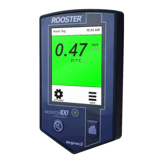
Rooster™ Monitor100 USER MANUAL Soft Buttons and Home Screen Layout Startup Delay Indicator Night Setback/Mute Indicator Asset Tag Time of Day Face Velocity Status Color (Green, Yellow (touch to toggle units) or Red) Air Temperature Alert Banner (touch to toggle units) Settings Menu Quick access to current configuration settings... - Page 5 Rooster™ Monitor100 USER MANUAL ON-SCREEN ALERT BANNERS A yellow banner will appear beneath on-screen velocity readings to alert users regarding various scenarios: Low Airflow, Power Failure Home TOGGLE VELOCITY UNIT TYPE Instantly toggle displayed velocity units from m/s to fpm, or vice versa, by pressing on the displayed velocity reading on the home screen.
- Page 6 Rooster™ Monitor100 USER MANUAL instructions on how to setup night setback alarm thresholds. Home> Settings>System>Alarms/Sound>Alarm Controls>Night Setback ALARM LATCHING EH&S or Certifier users can setup latched alarms to indicate that a low airflow state has occurred in the “Alarm Controls” menu. User must then enter a EH&S or Certifier passcode to unlatch an alarm.
-
Page 7: Rear Panel Layout For Advanced Connections
*2-position connectors will fit 2-position orderable Part Number: Phoenix Contact 1803578 Table 1 Connections - Rear Panel of Display Module Optional Sash Switch kit, Degree Controls P/N: 62310AS004 includes 10-postion Phoenix Contact connector. Rooster™ Monitor100 USER MANUAL 62310MN000-A04 7 of 33... -
Page 8: Technical Specifications
CE, RoHS Connection and Wiring Information Degree Controls recommends 18-24 AWG wire be used for all wiring connections to the input and output connectors. The Sensor and Power Entry connections have been prepared for you, and merely need to be pulled through the openings and connected to the display module. If the Sash Switch option is purchased, this is pre-connectorized for you as well. -
Page 9: Sash Input
Monitor100 to achieve a different result, and any proximity sensor may be implemented. Degree Controls can provide you with an optional Sash Position Sensor comprised of (1) inductive proximity sensor and (1) 10-position connector which mates to the input connection of the display module. -
Page 10: Alarm Outputs
Rooster™ Monitor100 USER MANUAL Off (default): In this state, when the Night Setback signal is asserted, the Monitor100 will ignore it. Alarm Outputs The Rooster Monitor100 alarms for airflow and sash position. The Alarm outputs are relay outputs available on the output connection of the display module. I/O polarity logic of outputs may be reversed as well. -
Page 11: Probe Sensor
Rooster™ Monitor100 USER MANUAL Probe Sensor Figure 3 Probe Sensor Sidewall Sensor Figure 4 Sidewall Sensor Inline Sensor Figure 5 Inline Sensor Rooster™ Monitor100 USER MANUAL 62310MN000-A04 11 of 33... -
Page 12: Installation
Rooster™ Monitor100 USER MANUAL Installation Installation of the Rooster Monitor100 involves selecting and preparing appropriate locations for the alarm module and sensor, wiring and connecting the unit, and then mounting both the alarm module and sensor securely. Back Plate Mounting Options - Alarm Module The Rooster Monitor100 is mountable to a cabinet or wall panel by first securing the back plate. -
Page 13: Probe Sensor
Rooster™ Monitor100 USER MANUAL 4. Secure back plate. 5. Mount the sensor. See below for sensor installation descriptions with different sensor styles. 6. Feed power and sensor wire harnesses through the opening(s) and make connections to the Rooster Monitor100 alarm module. Make any other optional connections to the alarm module. -
Page 14: Sidewall Sensor
4. Tighten mounting nut (B) in left-hand direction. 5. Make sure the sensor head faces airflow by positioning the probe elbow in the flow direction. A gland fitting is included with the Probe sensor. (Gland Fitting, Degree Controls P/N: HA1203) Curve in sensor probe aligns wire... - Page 15 Rooster™ Monitor100 USER MANUAL Self-tapping mounting screw Extends through wall, no ducting needed Figure 11 Sidewall Sensor on Single Walled Cabinet 10-16 x 1” self-drill screw RJ11 connection to Rooster Monitor100 Figure 12 Sidewall Sensor Mounting – Single Walled Cabinet Figure 13 Sidewall Sensor Mounting Dimensions Rooster™...
-
Page 16: Dual Walled Cabinet
Rooster™ Monitor100 USER MANUAL Dual Walled Cabinet For those installations where the Sidewall sensor will be on the front face of the fume hood, and a duct is needed to create an airflow path from the front face to the inside face of the cabinet, the “dual walled”... -
Page 17: Inline Sensor
½” flow tube being used by another monitor. The suggested installation procedure is depicted below. *Inline sensor includes sensor and tubing only. Call Degree Controls for pricing on additional installation components. Rooster™ Monitor100 USER MANUAL 62310MN000-A04 17 of 33... -
Page 18: Boot Up Procedure
Rooster™ Monitor100 USER MANUAL RJ11 connection to Rooster Monitor100 Exterior cabinet 10-16 x 1” surface self-drill screw Flow-through tube for ½” tubing connections Figure 18 Inline Sensor Includes Interior cabinet Sensor with Cable and Tubing Only surface Figure 19 Suggested Inline Sensor Installation Boot Up Procedure The Rooster does not have a power-on switch and will become energized as... -
Page 19: Access Tier Privileges: User, Eh&S & Certifier
Rooster™ Monitor100 USER MANUAL Access Tier Privileges: USER, EH&S & CERTIFIER Users have the ability to customize their containment Manufacturer default passcodes: cabinets within a defined set of options for each authorization level. There are three levels of access to the EH&S = 8377 Rooster : User, EH&S/Facility Manager and Certifier. -
Page 20: Set/Change Passwords
Rooster™ Monitor100 USER MANUAL Set/Change Passwords To change or set a password, follow this GUI path to trigger the password change sequence: Home> Settings>System>Advanced>Change Passwords You will have to enter an EH&S or Certifier passcode to get access to the “Advanced” menu. To change either the EH&S or Certifier passcode, you must first re-enter the old passcode. - Page 21 Rooster™ Monitor100 USER MANUAL 6. Before beginning the calibration process, select the When When Sensor Type to be calibrated. The choices are Probe, complet complet Sidewall, or Inline. There are a few key differences in your your the setup process for both Probe and Sidewall/Inline — initial initial these steps are outlined below:...
-
Page 22: Calibration Troubleshooting
Rooster™ Monitor100 USER MANUAL 9. Once valid set points have been defined, the calibration sequence will end with a “Calibration Successful!” message. If a "Calibration Failure" message is received instead, proceed to the troubleshooting section, or repeat the calibration procedure. Calibration Troubleshooting If you receive a “Calibration Failure”... -
Page 23: Alarm Threshold Configuration
Rooster™ Monitor100 USER MANUAL Alarm Threshold Configuration 1. To set your alarm threshold, follow the menu path below: Home> Settings>Thresholds>Adjust Thresholds 2. To set alarm thresholds, first define an alarm trip point and an alarm clear point. The alarm trip point is the air velocity value that will trigger an alarm. -
Page 24: Alarm Controls
Rooster™ Monitor100 USER MANUAL Alarm Controls To provide our users with full customization of the alarm behaviors that are best suited for their facilities and unique conditions, the Rooster Monitor100 allows authorized users (Certifier & EH&S) to set night setback, ringback, alarm delay, startup delay, latching, alarm tone and airflow resolution preferences. -
Page 25: Alarm Delay
Rooster™ Monitor100 USER MANUAL Settings Definition Disables ringback. If an alarm is muted, the alarm remains muted for the entire duration of the alarm event. A muted alarm will ringback audibly after 10 seconds if the unit is still in an active alarm state. -
Page 26: Startup Delay
Rooster™ Monitor100 USER MANUAL Alarm Delay Definition Alarm is cleared after 5 seconds if velocity readings are above the alarm clear threshold. Alarm is triggered after 5 seconds if velocity readings are below the alarm trip threshold. Alarm is cleared after 10 seconds if velocity readings are above the alarm clear threshold. -
Page 27: Backlight Dimming
Rooster™ Monitor100 USER MANUAL Low Flow alarm - Tone 1 Sensor alarm - Off Sash alarm - Tone 2 Alarm Tone Settings supercedes Minimum Volume settings. Alarm Type Definition The audible alarm is off. Tone 1 Alarm plays Tone 1. Tone 2 Alarm plays Tone 2. -
Page 28: Airflow Resolution
Rooster™ Monitor100 USER MANUAL Sensitivity Definition Increases filtering providing smoother readings, but slower response. Default setting. Provides a balance between smooth readings and reasonable response times. High Decreases filtering resulting in greater fluctuation of readings with faster response. Airflow Resolution For advanced users, displayed velocity units can be configured to display in an alternate resolution. -
Page 29: Import/Export
Rooster™ Monitor100 USER MANUAL Import/Export EEPROM The user can save all current Rooster settings to a USB thumb drive for future use. Importing the EEPROM configuration file to other Rooster s in your facility ensures operational consistency and saves valuable setup time. Plug a USB thumb drive into the Rooster navigate to the Import/Export menu to select the Import EEPROM or Export EEPROM option. -
Page 30: Usb Field Upgrade Procedure
Rooster™ Monitor100 USER MANUAL USB Field Upgrade Procedure A Rooster with firmware preceding version 1.04 may be upgraded to version 1.04 using the bootloader, however, existing calibration data will be lost, and all settings will be reset to factory defaults. Thus, this update should only be done during annual certification, where the certifier would be recalibrating anyway, OR, if the client approves forcing a recalibration. -
Page 31: Factory Reset Procedure
Rooster™ Monitor100 USER MANUAL 2. Insert USB thumb drive into left side of Rooster Monitor100. 3. Depress and hold the “Home” button, while reapplying power to your unit. (Hard Home button must be depressed while Rooster powers up in order to enter the firmware update sequence.) 4. -
Page 32: Gui Map
Rooster™ Monitor100 USER MANUAL GUI Map Rooster™ Monitor100 USER MANUAL 62310MN000-A04 32 of 33... -
Page 33: Warranty
Rooster™ Monitor100 USER MANUAL Warranty For a period of one (1) year following the date of delivery, and subject to the other provisions of this Warranty Section, DegreeC warrants that all new products that are both (a) manufactured by DegreeC and (b) purchased directly from DegreeC (or an authorized distributor of DegreeC) shall be free of material defects in materials and workmanship.
Need help?
Do you have a question about the Rooster Monitor100 and is the answer not in the manual?
Questions and answers