
Related Manuals for IMI NORGREN VM10 5 Series


Summary of Contents for IMI NORGREN VM10 5 Series
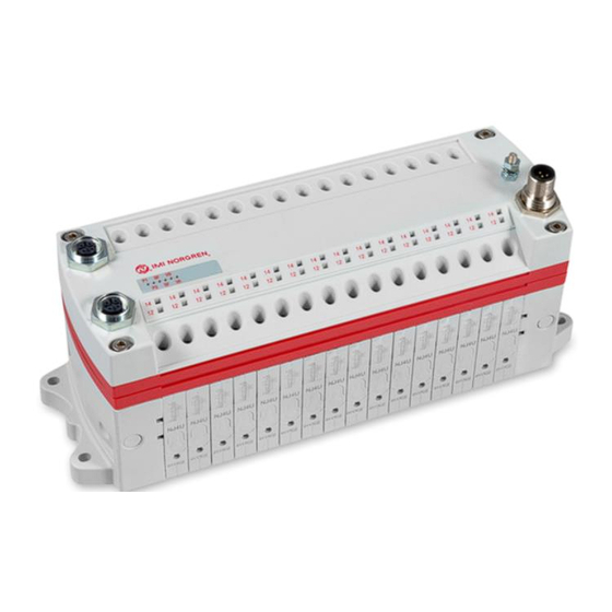
- Page 1 Valve island VM10 with EtherNet/IP Interface 8, 10, 12 or 16 stations Operation & Service Manual...
- Page 2 Operation & Service Manual Valve islands VM10 EtherNet/IP Change history: The Change history reflects all changes of the Operation & Service Manual, which were done after the initial release. Index Chapters Change description Date Name Set up initial version 08/02/2017 Modifications have been updated 28/02/2017 New chapter added...
-
Page 3: Table Of Contents
Operation & Service Manual Valve islands VM10 EtherNet/IP Content About this documentation..................... 5 Important hints ......................6 Grounding and equipotential bonding ..............6 Electrical Connections of the VM10 valve islands ............7 EtherNet/IP - Bus connectors PORT 1 & PORT 2 ..........8 POWER supply connector .................. - Page 4 Operation & Service Manual Valve islands VM10 EtherNet/IP Contact information Norgren GmbH Site Fellbach Stuttgarter Straße 120 70736 Fellbach Tel: +49 711 5209-0 Construction & Design is subject to change © 2018 Norgren GmbH 07/2018...
-
Page 5: About This Documentation
Operation & Service Manual Valve islands VM10 EtherNet/IP 1. About this documentation This Operation & Service Manual contains the information to set up and operate the VM10 valve islands with EtherNet/IP interface and to detect and resolve problems. Note In addition to the specific information for the EtherNet/IP variants, all data sheets for the VM10 valve island series are applicable and remain valid. -
Page 6: Important Hints
Operation & Service Manual Valve islands VM10 EtherNet/IP Important hints Grounding and equipotential bonding Proper grounding and equipotential bonding are very important to protect against electromagnetic interferences in Ethernet networks. In order to reduce potential impact, grounding of the Ethernet cable screen should be done at both ends of every cable (i.e. -
Page 7: Electrical Connections Of The Vm10 Valve Islands
Operation & Service Manual Valve islands VM10 EtherNet/IP Electrical Connections of the VM10 valve islands 1. Port 1 bus connector for EtherNet/IP (4 pins M12 D-coded female connector) 2. Port 2 bus connector for EtherNet/IP (4 pins M12 D-coded female connector) 3. -
Page 8: Ethernet/Ip - Bus Connectors Port 1 & Port 2
Operation & Service Manual Valve islands VM10 EtherNet/IP EtherNet/IP - Bus connectors PORT 1 & PORT 2 M12 / 4 pins / female connector / D-coded Pin no. Function Transmission Data + (TD+) Receive Data + (RD+) Transmission Data - (TD -) Receive Data - (RD -) Earth screw FE (functional earth) -
Page 9: Commisioning
Operation & Service Manual Valve islands VM10 EtherNet/IP Commisioning The configuration of the EtherNet/IP valve island is done via inclusion of the device description file (EDS file) „002A002B1XXXX0100.EDS“. The device description file is required to be included for the configuration of the corresponding EtherNet/IP - Controller. The following steps are necessary. -
Page 10: Hardware Configuration: Select Valve Island
Operation & Service Manual Valve islands VM10 EtherNet/IP After the installation the new module is shown in the catalogue. Hardware configuration: Select valve island After the successful installation of the EDS file, the module configuration is needed. In context menu choose “New Module” after right-clicking on “Ethernet”. Construction &... - Page 11 Operation & Service Manual Valve islands VM10 EtherNet/IP In the module catalog choose the corresponding VM10 valve island and click on „Create“. The picture bellow shows “Select Module Type” – Dialog In the following dialogue tab “General” set the “Name” and the correct “IP Address” of the module. Construction &...
- Page 12 Operation & Service Manual Valve islands VM10 EtherNet/IP In dialogue tab “Connection” change “Requested Packet Interval (RPI)” greater than or equal to 10 ms and click “OK”. The RPI times has a direct impact to the busload. Note: The lower the cycle times, the higher the busload. The picture bellow shows module tree with the new added module.
-
Page 13: Set Up Ip Address
Operation & Service Manual Valve islands VM10 EtherNet/IP Set up IP Address 4.3.1 Using a DHCP Server As default the VM10 valve island is set up as a DHCP client. In this mode IP Address has to be assigned using a DHCP server or a similar tool. This has to be repeated after each power cycle. The following example shows the IP Address assignment using Rockwell Automations BOOTP_DHCP Tool. - Page 14 Operation & Service Manual Valve islands VM10 EtherNet/IP Attribute 5 contains the configuration parameters required to operate as a TCP/IP node. At least network address and network mask needs to be configured. Attribute 5 of TCP/IP Interface Object: Interface Configuration Next table shows the structure of the interface configuration attribute Structure of Attribute 5: Interface Configuration Construction &...
-
Page 15: I/O Connection Via Assembly Object
Operation & Service Manual Valve islands VM10 EtherNet/IP I/O connection via Assembly Object The Assembly Object is used to bundle attributes of different objects, to use only one connection exchanging I/O data. One instance is used for input data and one for output data. Bit allocation valve stations The following picture shows exemplarily a VM10 with 12 valve stations. -
Page 16: Input Data (Assembly Object Instance: 101D)
Operation & Service Manual Valve islands VM10 EtherNet/IP Input data (Assembly Object Instance: 101d) The following table shows the bit allocation of the input data for VM10 with 8, 10, 12 and 16 valve stations. Valve stations Function Byte# Byte# Byte# Byte# UV-VB... -
Page 17: Output Data (Assembly Object Instance: 100D)
Operation & Service Manual Valve islands VM10 EtherNet/IP Output data (Assembly Object Instance: 100d) The following table shows the bit allocation of the output data for VM10 with 8, 10, 12 and 16 valve stations. Valve stations Byte# Byte# Byte# Byte# V04-12 V04-14... -
Page 18: Solenoid Object
Operation & Service Manual Valve islands VM10 EtherNet/IP Solenoid Object Object Class: 100d 1…16 Instances: 8 stations 1…20 10 stations 1…24 12 stations 1…32 16 stations Each solenoid is a separate instance of the Solenoid Object. The allocation between Instance ID and solenoid is shown in the following table: Valve 1…4 V04-12... -
Page 19: Diagnostics And Leds
Operation & Service Manual Valve islands VM10 EtherNet/IP Diagnostics and LEDs Status LEDs 7.1.1 Status LEDs description LED type Description Link Port 1 (TX/RX & Link) Link Port 2 (TX/RX & Link) Network Status Module Status Valves Power Supply Status Electronic Power Supply Status 7.1.2 Link states for Port P1 and Port P2 Link Status... -
Page 20: Electronics Power Supply Status, Led (Vb)
Operation & Service Manual Valve islands VM10 EtherNet/IP 7.1.5 Electronics Power Supply Status, LED (VB) Electronics Power Supply States LED State Voltage O.K. green Undervoltage flashing red Overvoltage 7.1.6 Valve Power Supply Status, LED (VA) Valve Power Supply States LED State Voltage O.K. -
Page 21: Valve Slice Status Leds
Operation & Service Manual Valve islands VM10 EtherNet/IP Valve slice Status LEDs Each valve station has 2 separate status LEDs depending on its configuration, which indicate the control states “14” and “12” for the corresponding pilot valve solenoids. Please note, that an error state will only be indicated if the valve island diagnostics for the corresponding valve has been activated in “Solenoid Object Attribute 3”. -
Page 22: Output Behavior In Fault Condition (Idle Mode/Fault Mode)
Operation & Service Manual Valve islands VM10 EtherNet/IP 8. Output behavior in fault condition (Idle mode/Fault mode) The Fault Mode defines the behavior of the outputs while communication errors. The VM10 valve island executes the idle mode if requested by the controller. The following states could be taken by the outputs in case of executing Idle Mode or Fault Mode: ... -
Page 23: Properties Ethernet/Ip Interface
Operation & Service Manual Valve islands VM10 EtherNet/IP 9. Properties EtherNet/IP Interface Specification Comments Number of ports Link Speed 100Mbit/s Duplex Mode Full Duplex QuickConnect DLR Mode Device Level Ring EtherNet/IP (ODVA Certification) Compliant to IEC61158 IP Address modes Static, BOOTP, DHCP EDS languages Construction &... -
Page 24: Electrical Data
Operation & Service Manual Valve islands VM10 EtherNet/IP 10. Electrical data Requirement Comment Valve voltage range (VA) 24VDC +/-10% PELV Electronics voltage range (VB) 24VDC +/-25% PELV VA: 150mA + n x 30mA Maximal currents: n = number of activated valves VB: 400mA Voltages are galvanic decoupled Protection against polarity reversal... -
Page 25: Technical Data
Operation & Service Manual Valve islands VM10 EtherNet/IP 11. Technical data Medium: Compressed air, filtered, lubricated and non-lubricated Operational: Spool valve indirectly actuated Port sizes: Ø 3 mm, 4 mm, 6 mm (1/8, 5/32, 1/4) Operating pressure: -0,9 ... 8 bar (116 psig) Flow: ‘C’... - Page 26 Operation & Service Manual Valve islands VM10 EtherNet/IP Customer support Email contact: Anfragen.Ventilteam@imi-precision.com Norgren GmbH Werk Fellbach Stuttgarter Straße 120 70736 Fellbach Tel: +49 711 5209 -0 The data specified above only serve to describe the product. No statements concerning a certain condition or suitability for a certain application can be derived from our information.
Need help?
Do you have a question about the VM10 5 Series and is the answer not in the manual?
Questions and answers