Table of Contents
Advertisement
Quick Links
CSL
Eickhoff Diagnostic Charging Station
User Manual
Issue 1.6
(New Bluetooth module and Software)
Controlled Systems Limited
Ryder Close, Swadlincote, Derbyshire. DE11 9EU. England
TEL: +44 (0)1283 216231 / FAX: +44 (0)1283 552937 / sales@controlledsystemsltd.co.uk
November 2015 – Issue 1.6
Eickhoff Diagnostic Charging Station
1 / 30
Advertisement
Table of Contents

Subscribe to Our Youtube Channel
Related Manuals for CSL Eickhoff


Summary of Contents for CSL Eickhoff
- Page 1 Eickhoff Diagnostic Charging Station User Manual Issue 1.6 (New Bluetooth module and Software) Controlled Systems Limited Ryder Close, Swadlincote, Derbyshire. DE11 9EU. England TEL: +44 (0)1283 216231 / FAX: +44 (0)1283 552937 / sales@controlledsystemsltd.co.uk November 2015 – Issue 1.6 Eickhoff Diagnostic Charging Station...
-
Page 2: Table Of Contents
Table of Contents Features ..................3 Eickhoff Diagnostic Charging Station Overview ........3 Eickhoff Diagnostic Charging Station Features ........3 Description ..................4 Connections ................... 5 Installation ..................7 Operating the Diagnostic Charging Station ........8 Powering Unit On ................... 8 A Search for Bluetooth devices begins ........... -
Page 3: Features
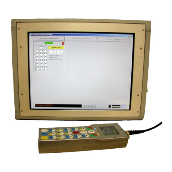
Features Eickhoff Diagnostic Charging Station Overview 15” 1024 x 768 SVGA colour display with touch screen Six radio handset charging ports Wire bound connector for testing wire bound handset 12 Volt auxiliary supply output terminals ... -
Page 4: Description
The unit is equipped with a touch screen for easy onsite operation, negating the need to use a keyboard or mouse for every day testing. Radio handsets are detected during a search when they are on charge. November 2015 – Issue 1.6 Eickhoff Diagnostic Charging Station 4 / 30... -
Page 5: Connections
Ethernet port CANBUS ‘D’ connector USB port Radio Handset charging connectors Wire bound handset socket The external connections on the left hand side of the unit are shown below: November 2015 – Issue 1.6 Eickhoff Diagnostic Charging Station 5 / 30... - Page 6 Cooling Fan ON / OFF Switch Power IEC Socket (Fuse Holder Below) November 2015 – Issue 1.6 Eickhoff Diagnostic Charging Station 6 / 30...
-
Page 7: Installation
Ventilation to and from the unit must not be restricted The operators should be trained in the safe use of the equipment, such that operational hazards arising from misuse are avoided. November 2015 – Issue 1.6 Eickhoff Diagnostic Charging Station 7 / 30... -
Page 8: Operating The Diagnostic Charging Station
The unit is powered on by operating the switch on the left hand side of the unit and will automatically load the diagnostic display shown below Touch the “SEARCH FOR HANDSETS” button to start the search. November 2015 – Issue 1.6 Eickhoff Diagnostic Charging Station 8 / 30... -
Page 9: A Search For Bluetooth Devices Begins
OFF if the handset is logged on to it (Handsets online to a Radio Receiver will not be found). The search will find all discoverable Bluetooth devices including mobile phones, laptops etc. but will then discard any that are not Radio Handsets. November 2015 – Issue 1.6 Eickhoff Diagnostic Charging Station 9 / 30... -
Page 10: Select Which Handsets Are Required
On this screen simply select using the touch screen the handsets you wish to connect. Once highlighted simply click the OK button and the unit will connect to the specified handsets. November 2015 – Issue 1.6 Eickhoff Diagnostic Charging Station 10 / 30... -
Page 11: Screen Showing Connected Handsets
Screen showing connected handsets A maximum of 6 radio handsets can be displayed at once. Note: If a wire bound handset is connected then this is reduced to 5. November 2015 – Issue 1.6 Eickhoff Diagnostic Charging Station 11 / 30... -
Page 12: Testing For Correct Operation Of Handset Keys
Testing for correct operation of handset keys The above shows 2 handset keys depressed – all keys are monitored in this way November 2015 – Issue 1.6 Eickhoff Diagnostic Charging Station 12 / 30... -
Page 13: Radio Handset Display Highlighted
Touch the panel again to de-select it. With a detected radio handset highlighted the “update software”, “update font chip” and “Set S/N & H/W Version” buttons become available for that handset. November 2015 – Issue 1.6 Eickhoff Diagnostic Charging Station 13 / 30... -
Page 14: Updating Radio Handset Software
A password is then required to continue and a password box is displayed: The “Enter Password” box. The Password is entered by touching or selecting the squares as shown above. This takes the form of an uppercase “E” November 2015 – Issue 1.6 Eickhoff Diagnostic Charging Station 14 / 30... - Page 15 Selecting OK shows a “select file” box containing a list of available files. Select the required file to update the radio handset Select OK to start the update. November 2015 – Issue 1.6 Eickhoff Diagnostic Charging Station 15 / 30...
- Page 16 A progress bar indicates the current updating progress as shown below: On completion touch the “OK” button to return from the update screen November 2015 – Issue 1.6 Eickhoff Diagnostic Charging Station 16 / 30...
-
Page 17: Updating The Radio Handset Font Chip
A password is then required to continue and a password box is displayed: The “Enter Password” box is available The Password is entered by selecting (touching) the squares as shown above. This takes the form of an uppercase “E” November 2015 – Issue 1.6 Eickhoff Diagnostic Charging Station 17 / 30... - Page 18 On selecting “OK”, the download automatically starts as shown below: On completion touch the “OK” button to return from the update screen Note: This update takes approximately 40 minutes to complete November 2015 – Issue 1.6 Eickhoff Diagnostic Charging Station 18 / 30...
-
Page 19: Updating Radio Handset S/N And H/W Versions
A password is then required to continue and a password box is displayed: The “Enter Password” box is available The Password is entered by selecting (touching) the squares as shown above. This takes the form of an uppercase “E” November 2015 – Issue 1.6 Eickhoff Diagnostic Charging Station 19 / 30... - Page 20 Move the highlight to other fields that are required to be altered. When happy with the entry, click the OK button to send to the handset. November 2015 – Issue 1.6 Eickhoff Diagnostic Charging Station 20 / 30...
-
Page 21: Turning Off A Radio Handset
After a Radio Handset is turned off it is displayed as “Offline” as shown above. Touch “RECONNECT HANDSETS” button to try and reconnect any radio that is offline. November 2015 – Issue 1.6 Eickhoff Diagnostic Charging Station 21 / 30... - Page 22 Offline handsets are attempted (up to 3 times) to be reconnected. If successful the handset will come online again. If not it will stay as offline. November 2015 – Issue 1.6 Eickhoff Diagnostic Charging Station 22 / 30...
-
Page 23: Wire Bound Handset Display
The keys can be tested the same as the radio handsets. When a wire bound handset is connected the maximum number of radio handsets which can be displayed is limited to 5. November 2015 – Issue 1.6 Eickhoff Diagnostic Charging Station 23 / 30... -
Page 24: Rf Power Sensor
These occasional low readings are normal (this is how Bluetooth works) and therefore should be ignored only looking for the long periods that the reading is green and around 65mW. November 2015 – Issue 1.6 Eickhoff Diagnostic Charging Station 24 / 30... - Page 25 Before checking the RF power the RF power level on the handset should be set to RF4/MAX – see the “Eickhoff Bi-Di Radio Mk2 User Manual” for details. *The RF power meter is calibrated to read Bluetooth power from a MK2 Radio Handset and using the factory supplied TNC lead only.
-
Page 26: Using Vnc Connectivity Over Ethernet
5.13 Updating Diagnostic Station S/W and adding new .hex Files 1) Copy the required files (Eickhoff Diagnostic Station.exe and any new handset software version – EHRv#_##.hex) onto a pen drive and insert into the USB port on the RHS of the diagnostic station. - Page 27 4) Navigate to folder D:\Eickhoff Diagnostic\ and rename “Eickhoff Diagnostic Station.exe” to “old Eickhoff Diagnostic Station.exe” 5) From the pen drive (E:\) copy “Eickhoff Diagnostic Station.exe” to D:\Eickhoff Diagnostic\. 6) Copy any new software .hex file (EHRv#_##.hex ) and paste into D:\Updatefiles\ 7) Unmount and remove the pen drive.
-
Page 28: Canbus / Mk2 Machine Radio C515184 Test
5.14 CANBUS / MK2 Machine Radio C515184 Test 1) Select Diagnostic Station software “CSL Eickhoff CANBUS Radio Test Program MK2”. 2) Connect Machine Radio to Diagnostic Station 12Vdc O/P terminals and connect Machine Radio (X2-CANBUS) to Diagnostic Station “CANBUS” connector. - Page 29 November 2015 – Issue 1.6 Eickhoff Diagnostic Charging Station 29 / 30...
-
Page 30: Mechanical Details
For more detailed information about the take-back and recycling contact Controlled Systems Ltd. November 2015 – Issue 1.6 Eickhoff Diagnostic Charging Station 30 / 30...
Need help?
Do you have a question about the Eickhoff and is the answer not in the manual?
Questions and answers