
Summary of Contents for Hetronic Locomotive Nova XL
- Page 1 LOCOMOTIVE PERATING NSTRUCTIONS OCOMOTIVE YSTEM www.hetronic.com LOCAL BUT GLOBAL OOPMN_LNO__009 April 2015...
-
Page 2: Table Of Contents
TABLE OF CONTENTS SAFETY ................................4 SAFETY ALERTS ............................4 NOTATIONS ..............................4 PRACTICES AND LAWS ..........................4 REQUIRED OPERATOR TRAINING ....................... 4 POSSIBLE SOURCES OF DANGER ......................4 PROTECTIVE FEATURES ..........................4 TO STOP IN AN EMERGENCY ........................4 MAINTENANCE ............................... - Page 3 CHANGING YOUR BATTERY ........................... 11 DISPOSABLE BATTERIES: ........................11 RECHARGEABLE BATTERIES (68108580.A): ..................11 RECHARGING YOUR BATTERIES (OPTIONAL)..................11 FAST CHARGE ............................11 BATTERY DISPOSAL ............................ 12 OPERATING YOUR TRANSMITTER ........................ 13 TRANSMITTER .............................. 13 READ THIS FIRST ............................13 YOUR OPERATING RANGE .........................
- Page 4 INCREASE SPEED AGAIN ........................16 REDUCE SPEED ............................16 COAST ............................... 17 ROLL BACK PROTECTION .......................... 18 DATA LOGGING (option) ..........................18 GPS and/or GSM (option) ..........................18 VIDEO (option) ............................... 18 LCD, LED AND OPTIONAL RECEIVER DISPLAY INDICATOR MEANINGS ..........19 Table 1: LCD Indicators and Meanings .....................
-
Page 5: Safety
SAFETY SAFETY ALERTS POSSIBLE SOURCES OF DANGER The safety alert symbol is used in decals on the unit This device is part of a system that makes remote and with proper operation procedures in this manual. control via radio signals possible. However, the transmission of control commands can take place Understand the safety message. -
Page 6: Introduction
I NTRODUCTION Thank you for purchasing the Hetronic radio remote Before start up, ALWAYS confirm that the machine control system. Hetronic radio remote controls and radio remote control Stop functions work provide outstanding remote control value, quality, properly. performance, and safety. Understand all Safety Precautions provided in the manuals and review control functions and operation YOUR MANUALS... -
Page 7: Installation Considerations
I NSTALLATION C ONSIDERATIONS Read and understand the following considerations to ensure the proper installation of your system: • Isolate the radio control system from the locomotive when operating in manual mode. • The relays in the radio control system are rated for up to 5 amps unless otherwise specified. -
Page 8: Components
COMPONENTS Use the following as guidelines; always refer to your drawings for your specific system. The components described in this section pertain to an MU installation system with isolation and a mast antenna. We are using this system as a reference. Other systems may have different components and/or configurations. Again, please refer to your drawings for your specific system as it may be different. -
Page 9: Locomotive Isolation Panel (H0-00132)
LOCOMOTIVE ISOLATION PANEL (H0-00132) This is not applicable for all other versions of locomotive panels. The isolation panel provides fusing for all external voltages from the locomotive. If a fuse or breaker has been overloaded, the locomotive LCD panel will display the error “FUSE”. -
Page 10: Independent & Ap Brake (K18008) - H Gladhand
REMOTE SPEED SENSOR (HL0004) The remote speed sensor provides closed loop feedback to the locomotive LCD panel. X2. The (K18008) – H G & AP B NDEPENDENT RAKE LADHAND direction switch should always be switched to the This Connects to locomotive pneumatic panel direction of the locomotive pneumatic panel. -
Page 12: Changing Your Battery
CHANGING YOUR BATTERY ou may power your transmitter with disposable or rechargeable batteries. Both types use adapter cases that are inserted into the back of the transmitter. Follow the instructions below for your battery type. DISPOSABLE BATTERIES: 1. Insert 3 AA batteries into the back of the Standard Battery Adapter... -
Page 13: Battery Disposal
BATTERY DISPOSAL AVOID ENVIRONMENTAL POLLUTION. Recycle your rechargeable batteries according to local recycling rules and regulations. If you have questions or problems operating your battery charger, please contact your dealer or Hetronic. Standard Hetronic rechargeable batteries are the nickel metal hydride type. These batteries have no “memory effect”... -
Page 14: Operating Your Transmitter
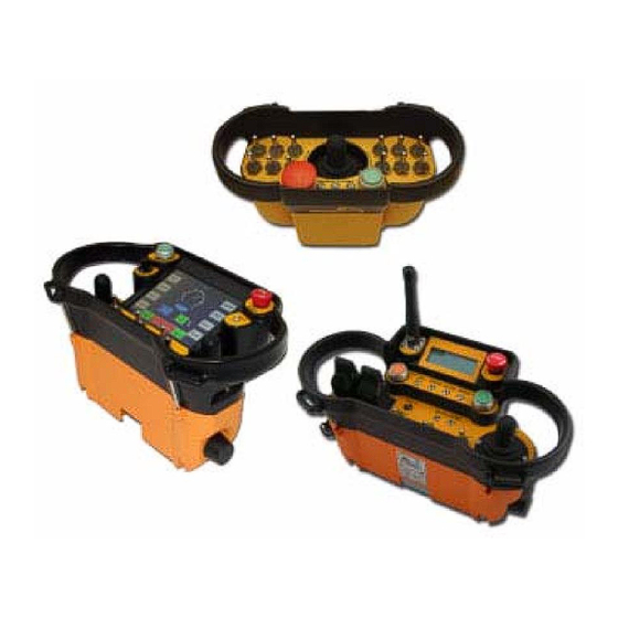
OPERATING YOUR TRANSMITTER TRANSMITTER Use the following as guidelines; always refer to your drawings for your specific system. READ THIS FIRST CHECKING HOSES AND THE CONNECTION Understand the following safety considerations and Before starting the transmitter, ensure that all hoses take the appropriate actions: and the MU connection is properly seated. -
Page 15: Starting Your Transmitter
8. Press the START button (S1) again if STARTING YOUR TRANSMITTER needed. WARNING: To avoid accidental start-up, 9. The safe mode indicator disappears and always press STOP when not in use. brake pressure readings appear on the NEVER operate the locomotive if the stop transmitter display. -
Page 16: Tilt Alarm
LARM SELECTING IRECTION For safety reasons, if the transmitter is tilted at an With the independent brakes applied, place the Reverser switch (S10) in the desired position. As a angle of 45 degrees or more for a specified amount standard, the independent brakes are automatically of time (default -2 seconds), the tilt alarm will sound applied if the operator fails to set the brake prior to a for a specified amount of time (default- 10 seconds). -
Page 17: Operating The Train Brakes
BELL FUNCTION (S7) PERATING THE RAIN RAKES Press the Bell button or toggle to sound the bell. Use the following as guidelines; always refer to (S5) HORN FUNCTION your drawing for your specific system. Press the Horn button or toggle to sound the horn. •... -
Page 18: Coast
handles (S2/3) to reduce speed. mph, the locomotive will coast to a stop and the brakes will apply after 20 seconds of no COAST movement. 3. If the locomotive is exceeding 5 mph, the Use the following as guidelines; always refer to your brakes will apply in a set amount of time at a drawings for your specific system. -
Page 19: Roll Back Protection
ROLL BACK PROTECTION Use the following as guidelines; always refer to your drawings for your specific system. 1. If applicable, please confirm that the direction switches on the remote Estop (HL0001) point toward the locomotive system. 2. If the wheel sensors detect the locomotive rolling the opposite direction than what is selected, the independent brakes will be applied to stop the roll back. -
Page 20: Lcd, Led And Optional Receiver Display Indicator Meanings
LCD, LED AND OPTIONAL RECEIVER DISPLAY INDICATOR MEANINGS The following icons appear on your transmitter LCD. See the meanings listed below: 1: LCD I ABLE NDICATORS AND EANINGS Safe Mode Return the throttle to NEUTRAL Antenna icon Transmitter is not receiving with a line feedback and is in control of the through it... - Page 21 3: R ABLE ECEIVER RAPHIC ISPLAY Graphic Color Image State Meaning STOP activated, brakes fully applied, functions disengaged STOP Text Blue STOP not activated Low air pressure warning from locomotive LOW AIR PRESSURE Text Blue No low air pressure warning from locomotive Low oil pressure warning from locomotive LOW OIL PRESSURE Text...
- Page 22 Numbers represent psi for each brake. The gauge TRAIN/LOCO BRAKE represents the joystick location. If bars fill the gauge, brakes are fully applied, If no bars, brakes are fully Icons/Text released. RADIO LINK Icon/Text Transmitter is communicating with receiver SAFE MODE Text System is in Safe Mode ACTIVE Text Transmitter is completely controlling system...
-
Page 23: Troubleshooting
TROUBLESHOOTING If the system does not operate after normal start-up, If you need more information, contact your dealer or follow the recommended troubleshooting sequence Hetronic. to help isolate the cause and determine corrective action. PROBLEM PROBABLE CAUSE CORRECTION Batteries not charging No power to the charger Apply power to the charger System not initializing after... -
Page 24: Maintenance
MAINTENANCE PNEUMATIC FILTERS MIST REMOVER FILTER (AF30P-060S) Pneumatic maintenance is dependent This filter removes moisture from the air. on the quality of the air in the PILOT FILTER (AFM30P-060AS) locomotive. If not dictated, all air Provides filtering for the pilot lines. filters should be replaced quarterly. -
Page 25: Weight, Dimensions And Transmitter Options Per Model
WEIGHT, DIMENSIONS AND TRANSMITTER OPTIONS PER MODEL Nova XL Up to 4 lbs (1840 g), with Weight: batteries Length: 11.2 in (285 mm) Dimensions: Height: 6.5 in (165 mm) Depth: 5.6 in (143 mm) • • Single axis 8-step joysticks •... - Page 26 LOCOMOTIVE www.hetronic.com © 2008 HETRONIC All rights reserved. No part of this publication may be reproduced, transmitted, transcribed, stored in a retrieval system, or translated into any language in any form by any means without the written permission of HETRONIC. Technical information subject to change without notice.
- Page 27 APPENDIX A Spare Parts Description Part Number List Price Pneumatic Panel with display See your drawings Call Factory Nova XL Transmitter See your drawings Call Factory System isolation Kit H0-00118 Call Factory System Isolation Kit w/ head light relay H0-00124...
- Page 28 APPENDIX B EPLACING ILTERS ESERVOIR ILTER • Remove the top 4 screws • Carefully lower the filter housing • Carefully pull the top of the filter housing toward you • Remove the filter and rubber ring 1...
- Page 29 • Remove rubber ring 2 and replace with new ring. • Insure rubber ring 1 is removed and replaced with the new ring. (Sometimes rubber ring 1 will be attached to filter top housing.) Re-assemble main reservoir filter housing using the four screws.
- Page 30 ILTERS To remove the Air filter; 1. Pull down the latch and push up on the bottom housing, turning it at the same time. 2. Then pull down on the bottom housing...
- Page 31 IRST ILTER • Unscrew the first air filter from the post • Discard the old filter • Replace with new filter AF30-060S. Insure proper seating and reinstall.
- Page 32 ECOND ILTER • Unscrew the second air filter from the post • Discard the old filter • Replace with new filter AFM30P-060AS. Insure proper seating and reinstall.
- Page 33 Install both the air filter housings; • Pull down the latch and push up on the bottom housing, turning it at the same time.
Need help?
Do you have a question about the Nova XL and is the answer not in the manual?
Questions and answers