Advertisement
Quick Links
SPECIFICATIONS
SIZE: 2.74"H x 1.68"W x 1.63"D
6.96 cm x 4.27 cm x 4.14 cm)
(not including ground strap)
WEIGHT: 5 oz
MOUNTING: Single gang switch box
OPERATING TEMP:
-4º to 122º F (-20º to 50º C)
RELATIVE HUMIDITY
20 to 75% non-condensing
PAIRING
INSTRUCTIONS
SETUP INSTRUCTIONS
The following five procedures should be reviewed completely prior to setting
up wireless switch units for use with CM xx WR wireless sensors or other RDT
Wireless devices. Consult the CM xx WR instruction sheet for additional sensor
setup procedures.
* Denotes factory setting
Switch Learn Mode (Pairing Mode) - see diagrams A-D above
The operational state when a switch unit will accept teach broadcasts from
ON
OFF
remote devices (e.g. sensors). Once received, the remote device will be added to
the switch unit's list of learned (paired) devices.
Step 1. Press and hold both switch buttons for 3 seconds (i.e. until button LEDs
start flashing together). See Diagram A above.
Step 2. Press switch's ON button 3 times (Diagram B above). Switch will now
be in "learn mode"
Notes:
1. While in Switch Learn Mode, the switch unit's LEDs will rapid flash then slow
blink the number of learned devices, and repeat (Diagram C above). See reverse
side for more details regarding device count blinkout.
2. The unit will stay in Switch Learn Mode for 2 minutes after last device was
learned, or until switch's ON button is pressed (Diagram D above).
3. Each time a new device is learned by (e.g. paired with) the switch, the switch
will toggle its relay. Wait a minumum of 4 seconds before pairing another device.
Sensor Teach Mode - see diagram C above
The operational state of a sensor when it will transmit its sensor ID to facilitate
pairing with other devices. This procedure is valid for CM xx WR series sensors.
For pairing other RDT
Wireless devices (e.g. rocker switch), consult instructions
TM
for that device.
Step 1. While switch is in Switch Learn Mode, press and release sensor button
2 times (Diagram C above)
Step 2. The sensor's LED will rapid flash when transmitting
Note:
1. Sensor resumes normal operation after one transmission is sent.
2. Use this procedure to unpair a sensor when a switch is in Unlearn mode.
Pairing a 2nd Switch - see diagram C above
To pair a 2nd SPODMR WR switch or a RDT
Wireless rocker switch (model
TM
ON
OFF
XCR 1PWH) follow below procedure:
Step 1. While the first SPODMR WR switch is in Switch Learn Mode, press and
release the 2nd switch's ON button (or rocker button) 3 times
(Diagram C above)
Sensor Switch 900 Northrop Road, Wallingford, CT 06492 Phone: 1.800.PASSIVE sensorswitch.com ©2014 Acuity Brands Lighting, Inc. All rights reserved 09/22/14 IS-SPODMR-WR-003
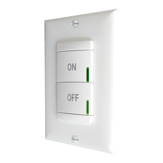
Wireless Wall Switch Instructions
MAXIMUM LOAD:
800 W @ 120 VAC / 1200 W @ 277 VAC
(Fluorescent/Tungsten/LED)
1A @ 24 VAC/VDC
MINIMUM LOAD: None
MOTOR LOAD: 1/4 HP
LOAD FREQUENCY: 50/60 Hz
SILICONE FREE
ROHS COMPLIANT
A.
1
1
ON
ON
OFF
OFF
C.
1
LEARN
ON
STATE
2
OFF
- OR -
D.
1
1
WHILE LEDs
LEARN
ON
STATE
FLASH
OFF
Operational Modes
Selection of Auto-On, Manual-On, or Predictive w/ Expiration operating modes.
ON
OFF
Step 1. Press and hold both switch buttons for 3 seconds (i.e. until button LEDs
TM
start flashing together)
Step 2. Press switch's ON button 5 times
Step 3. LED will begin flashing current setting (see selections 1-3 below)
Step 4. To change setting, press switch's ON button the number of times
corresponding to the new desired setting from the below choices:
1 - Auto-On:
Load will automatically turn on when occupied and off when vacant.
Pressing OFF will turn the load off and disable occupancy detection until ON
is pressed.
2 - Manual-On/Vacancy (*default for -SA option units):
Sensor functions as a vacancy detector, turning load off after occupancy is
no longer detected. Load must be turned on manually by pressing ON
button each time the room is entered. After the sensor times out, there is
a 10 second grace period in which detection of occupancy will automatically
turn the load back on.
3 - Predictive Mode w/ Expiration (*default for non-SA units):
Load will automatically turn on when occupied and off when vacant. Load
can be overridden to off by pressing OFF button. The load will remain off
if the room remains occupied. However, after the room becomes vacant, the
switch will revert back to auto on/off operation after Occupancy Time
Delay expires.
Step 5. Switch's LED will flash back current setting (repeats 3 times, then exits)
Occupancy Time Delay
The length of time a switch's relay will remain closed after the last occupied
ON
transmission from a sensor has been received. When paired with CM xx WR
OFF
series PIR sensors, the Occupancy Time Delay can be set from the switch (see
below) or from the sensor (recommended). See sensor instruction sheet.
When paired with CM PDT xx WR series Dual Tech sensors, the Occupancy Time
Delay must be set from the sensor (see sensor instruction sheet) and only after
it is paired with the SPODMR WR switch. This ensures that the sensor's internal
Microphonics time delay matches the switch's Occupancy Time Delay.
Step 1. Press and hold both switch buttons for 3 sec (until LEDs start flashing)
Step 2. Press switch's ON button 2 times
Step 3. LED will begin flashing current setting (see selections 1-13 below)
Step 4. To change setting, press switch's ON button the number of times
corresponding to the new desired setting from the below choices:
1 - 30 sec
5 - 10.0 min*
2 - 2.5 min
6 - 12.5 min
3 - 5.0 min
7 - 15.0 min
4 - 7.5 min
8 - 17.5 min
Step 5. LED will flash back new setting (repeats 3 times, then exits)
Notes:
1. The sensor Heartbeat Setting will need to be adjusted on the sensor to match
this setting if 5 minutes or under, and be set to 5 minutes for any higher setting.
(Model SPODMR WR xx)
WIRELESS FREQUENCY: 902 MHz (RDT™)
WIRELESS RANGE GUIDELINES:
Line of Sight: >100 ft (31 m); e.g. corridor
Plasterboard / Dry Wood: 98 ft (30 m), max 5 walls
Concrete: 32 ft (10 m), max 1 wall/ceiling
MAX PAIRED DEVICES: 20
B.
ON
OFF
ON
OFF
PRESS
REPEAT
2x
REPEAT
STEP C FOR EACH
STEP C FOR EACH
ADDITIONAL DEVICE
ADDITIONAL DEVICE
TO PAIR, THEN
TO PAIR, THEN
PRESS
PROCEED TO
PROCEED TO
3x
ON
STEP D.
ON
STEP D.
ON
OFF
OFF
OFF
E.
1
1x
ON
OFF
9 - 20.0 min 13 - 30.0 min
10 - 22.5 min
11 - 25.0 min
12 - 27.5 min
1
3x
ON
OFF
PLEASE NOTE:
PLEASE NOTE:
a) RELAY TOGGLES WHEN PAIRED WITH A NEW DEVICE.
a) RELAY TOGGLES WHEN PAIRED WITH A NEW DEVICE.
b) WHILE IN THE LEARN STATE, THE LEDs WILL FLASH
b) WHILE IN THE LEARN STATE, THE LEDs WILL FLASH
THE PAIRED DEVICE COUNT OR GIVE RANGE WARNING
THE PAIRED DEVICE COUNT OR GIVE RANGE WARNING
ERROR CODE.
ERROR CODE.
c) DEVICES EXIT THE LEARN STATE 2 MINS AFTER LAST
c) DEVICES EXIT THE LEARN STATE 2 MINS AFTER LAST
DEVICE PAIRED IF LEFT INACTIVE.
DEVICE PAIRED IF LEFT INACTIVE.
ON
PAIRING
COMPLETE
OFF
ADDITIONAL SETTINGS & MODES
Unlearn (Unpair)
When a teach broadcast is received by a switch from a remote device, it is
ON
OFF
removed from the unit's list of learned (paired) devices.
Step 1. Press and hold both switch buttons for 3 seconds (i.e. until button
LEDs start flashing together)
Step 2. Press switch's ON button 4 times
Notes:
1. While in Unlearn Mode, the unit will rapid flash then slow blink the
number of learned devices, and repeat.
2. Unit stays in Unlearn Mode for 2 minutes, or until one device is
unlearned. Press sensor button 2 times to unlearn (unpair).
3. Each time a new device is unlearned by (e.g. unpaired with) the switch,
the switch will toggle its relay.
Switch Diagnostic / Reset / Unlearn All
Provides options to reset and/or unlearn currently paired remote devices.
ON
OFF
Also provides total paired and inactive device count information.
Step 1. Press and hold both switch buttons for 3 seconds (i.e. until button
LEDs start flashing together)
Step 2. Press switch's ON button 9 times
Step 3. LED will begin flashing current setting (see selections 1-8 below)
Step 4. To change setting, press switch's ON button the number of times
corresponding to the new desired setting from the below choices:
1 - Do nothing*
2 - Reset settings to factory default and unlearn all
4 - Unlearn all paired devices
5 - Reset settings to factory defaults
(without unlearning devices)
6 - Learned Device Count
7 - Inactive Sensor Count
(paired sensors that have stopped transmitting)
8 - Unlearn All Inactive Sensors
Step 5. LEDs will flash back current setting (repeats 3 times, then exits)
Switch Status LED Operation
Controls the normal operation of the button's LEDs on the switch unit.
ON
OFF
Step 1. Press and hold both switch buttons for 3 seconds (i.e. until button
LEDs start flashing together)
Step 2. Press switch's ON button 11 times
Step 3. LED will begin flashing current setting (see selections 1-2 below)
Step 4. To change setting, press switch's ON button the number of times
corresponding to the new desired setting from the below choices:
1 - LEDs enabled* (indicates current status of relay)
2 - LEDs disabled
Step 5. LED will flash back current setting (repeats 3 times, then exits)
Note: In disabled mode, LEDs will still flash when button is pushed, device
is in Learn or Unlearn mode, or when device is flashing back a setting or
error code.
..
..
G
G
S
S
1 of 2
Advertisement

Related Manuals for Sensor Switch SPODMR WR Series


Summary of Contents for Sensor Switch SPODMR WR Series
- Page 1 5 minutes or under, and be set to 5 minutes for any higher setting. Sensor Switch 900 Northrop Road, Wallingford, CT 06492 Phone: 1.800.PASSIVE sensorswitch.com ©2014 Acuity Brands Lighting, Inc. All rights reserved 09/22/14 IS-SPODMR-WR-003 1 of 2...
- Page 2 —Connect the equipment into an outlet on a circuit different from that to which the receiver is connected. —Consult the dealer or an experienced radio/TV technician for help. Sensor Switch 900 Northrop Road, Wallingford, CT 06492 Phone: 1.800.PASSIVE sensorswitch.com ©2014 Acuity Brands Lighting, Inc. All rights reserved 09/22/14 IS-SPODMR-WR-003 2 of 2...
Need help?
Do you have a question about the SPODMR WR Series and is the answer not in the manual?
Questions and answers