Table of Contents
Advertisement
Quick Links
- 1 Chapter 1: Configuration through the Lan Using the Finder Program
- 2 Chapter 2: Configuration through an Rs232 Terminal Connection
- 3 Restore to Default Factory Settings
- 4 Chapter 3: Configuration through the Lan Using a Standard Browser
- 5 General / Ip Configuration
- 6 Settings / Accounts / Hidden Page Account
- Download this manual
Advertisement
Table of Contents

Summary of Contents for Neol ePowerSwitch 4 IEC R2
- Page 1 User Guide ePowerSwitch 4 IEC www.neol.com...
- Page 2 Neol S.A.S assumes no responsibility for errors within the documentation, the hardware or the software. Neol S.A.S reserves the right to change programs or the documentation from time to time without informing the user, errors and omissions excepted.
-
Page 3: Table Of Contents
CONTENTS Safety instructions ....................3 Read before use! ....................3 Part I : Description ....................4 Diagram ..............................4 Package list ............................... 4 Part II : Installation ....................5 Part III : Configuration .................... 6 Chapter 1: Configuration through the LAN using the Finder program............6 Chapter 2: Configuration through an RS232 Terminal connection ............ -
Page 4: Safety Instructions
Safety instructions Read before use! NOTE Safety instructions The ePowerSwitch devices can only be installed by qualified people with the following installation and use instructions. The manufacturer disclaims all responsibility in case of a bad utilization of the ePowerSwitch devices and particularly any use with equipments that may cause personal injury or material damage. -
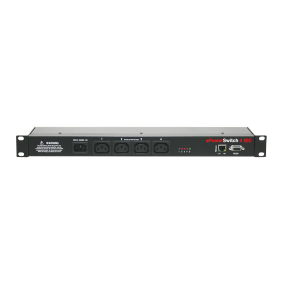
Page 5: Part I : Description
Part I : Description ePowerSwitch 4IEC is an extension lead that enables remote power control over IP or locally through an RS-232 Terminal connection. The built-in mini Web server allows individual control of the four sockets, using a browser. Its serial interface can be used to control the power outlets over a Terminal connection (KVM Switch, console server...) or to trigger a soft shutdown of a server with shutdown capabilities. -
Page 6: Part Ii : Installation
Part II : Installation Connection instructions 1. Use a shielded RJ45 network cable to connect your ePowerSwitch 4IEC to the network. 2. Use appropriated three-wire power cords (two poles plus ground) to connect your electrical devices to the ePowerSwitch 4IEC unit. 3. -
Page 7: Part Iii : Configuration
Part III : Configuration To use the ePowerSwitch 4IEC on your network, you must first configure its network parameters. Ask your network administrator for the parameters to use. There are three methods to configure the network parameters of the ePowerSwitch 4IEC: Chapter 1: Configuration through the LAN using the Finder program It is the simplest and fastest configuration method if you use Windows as operating system. -
Page 8: Chapter 2: Configuration Through An Rs232 Terminal Connection
DHCP: Check this box is you want to obtain the IP address, the subnet mask and the default gateway for your ePowerSwitch 4IEC via DHCP. Use of DHCP (Dynamic Host Configuration Protocol) requires a DHCP host to be set up on the network. -
Page 9: Serial Port Configuration
Special commands (type /? or /Help) /viewlog Display the log file /initlog Clear the log file /initadminaccount Restore default administrator password /restorefactconf Restore to factory default settings /help or /? Display this help Serial port configuration Connector: SUB-D9 female connector Pin configuration RS232 parameters Pin 2 = TxD (transmit data to the PC) -
Page 10: Chapter 3: Configuration Through The Lan Using A Standard Browser
Chapter 3: Configuration through the LAN using a standard Browser During the first installation, change temporarily the network settings of your PC according to the default network settings of the ePowerSwitch 4IEC. Factory network settings of the ePowerSwitch 4IEC: IP Address: 192.168.100.200 - Port: 80 Gateway: 255.255.255.0... -
Page 11: General / System Time
General / System time The system time of the ePowerSwitch 4IEC is used for synchronizing scheduling actions and to timestamp SNMP traps, Syslog information and internal logs. The system time can be set manually with the browser time of the connected computer or can be automatically synchronized with one or two NTP timeservers. Current System Time: This field shows the current system time of the ePowerSwitch 4IEC. -
Page 12: General / Smtp
General / SMTP This page is used to configure the SMTP mail transfer protocol. To send emails, you will need an SMTP server on the network and you will have to configure following parameters: SMTP Client enabled Check this box if you want to enable the SMTP protocol and send emails. SMTP Server Address Enter either the hostname or the IP address of your mail server. -
Page 13: General / Snmp
General / SNMP The ePowerSwitch 4IEC provides a built-in SNMP (Simple Network Management Protocol) agent, which enables you to manage the ePowerSwitch 4IEC through SNMP-based network management systems. The ePowerSwitch 4IEC MIB file enables to remotely read out the status of all power outlets and the values of all sensors (temperature, humidity, ambient light). -
Page 14: General / Trigger
General / Trigger Your Device has the ability to send a request over IP to another Device. This request can then be used to trigger an Action on the remote Device. Depending on your other Device, you could for instance switch on a Power Outlet, close or open a Relay or send an SNMP Trap, an email or a Syslog message. -
Page 15: General / Syslog
General / Syslog This page allows to define the address of one or two Syslog Servers. Primary Syslog Server Select this Checkbox and specify the IP address or the Hostname of your Primary Syslog Server. If you use a hostname, the system must be able to resolve queries for the hostname into IP address, so you must configure a Default Gateway and at least one DNS Server on the Network Settings Page (General/IP Configuration page). -
Page 16: General / Tools
General / Tools This page enables you to: - download and save the current settings of your ePowerSwitch 4IEC on your PC, - upload an existing configuration file to your ePowerSwitch 4IEC, - restore the factory settings, - download the ePowerSwitch 4IEC MIB file on your PC. Save: Click this button to save the current system settings onto your local hard drive. -
Page 17: Settings / Accounts
Settings / Accounts This page is used to create, activate, deactivate, modify and delete up to 40 accounts. - To activate or deactivate an account, check or uncheck the corresponding checkbox. - To modify an account, click on "Edit" next to the corresponding account. - To delete an existing account, click on "Delete"... -
Page 18: Settings / Accounts / Hidden Page Account
To add Groups to the current account, press the Ctrl key and click on the displayed Groups. The selected Groups are marked dark blue and their IDs are listed at the right side of the Groups field. This field appears only if you have already created at least one group (Settings/Groups Tab). Device: In this drop-down list, choose a device from which you want to add Inputs or Outputs to the current account. - Page 19 Activated This check box must be checked to activate the Hidden Page Account. It enables to deactivate temporarily this account while keeping all its settings for a later use. The Hidden Page Account cannot be deleted. User Name In this field, enter the name you want to give to the Hidden Page Account. The user name can be up to 32 characters long and contain alphanumeric characters.
- Page 20 Controlling Power Outlets Only Power Outlets which have been selected can be controlled over the Hidden Page. To select Power Outlets, go to the "Settings/Accounts" page and edit the Hidden Page Account. In the Inputs/Outputs field, selected the Power Outlets you want to control and click on the Arrow button next to the Inputs/Outputs field. The selected Power outlets appear in the right field, click on Apply Change to validate the configuration.
-
Page 21: Settings / Groups
Settings / Groups This page is used to create, modify and delete groups of power outlets which can be controlled by the ePowerSwitch 4IEC. This functionality is particularly useful if you have to control the power supply of devices using redundant power supplies. You can create groups including several power outlets distributed on several ePowerSwitch 8XS devices. -
Page 22: Settings / Peripherals - Epowerswitch 4Iec
Settings / Peripherals - ePowerSwitch 4IEC This page enables to label the device, the 4 power outlets of the ePowerSwitch 4IEC and the shutdown function. Names of up to 32 alphanumeric characters in length are supported and appear in log files, Syslog messages and SNMP traps to avoid confusions. - Page 23 Power up delay: In this field, enter the power up delay you want to define for each power outlet. Power up delay means the delay before the power outlet will take the defined status after power up. The delay can be set between 1 and 255 seconds, the value 0 means that no delay has to be applied after power up.
-
Page 24: Settings / Rules
Settings / Rules Rules are used to control actions according to a specific event. For example, you can define a rule to switch a power outlet OFF and send an alert message using different methods like SNMP or Syslog when a temperature, humidity, ambient light or current exceeds a predefined value or when a contact is open. - Page 25 7. Analog Input Monitoring Rule: This rule is used to control actions when an analog input (temperature, humidity, ambient light, current...) exceeds a predefined value. 8. xBus Peripheral Connection Rule: This rule is used to monitor the presence of xBus Peripherals and to trigger different actions when an xBus Peripheral is disconnected (cable disconnected or broken) or connected again.
-
Page 26: Settings / Rules - Schedule Rule
Settings / Rules - Schedule Rule This rule can be used to trigger user-specified actions according to a defined time table. The schedule rule is weekday based and the administrator can declare, for each weekday, a start time, an end time and after what time the rule should be repeated. - Page 27 Start Time Defines what time the rule starts. Repeat Time Defines the time period in which the rule repeats. Repeat Time cannot be set to zero. Stop Time Defines what time the rule ends. - End Time must be greater than or equal to Start Time. - If the rule has to be executed only once at the selected weekday, enter the same value for Start Time and End Time.
- Page 28 This type of Action appears and can be configured only if you have already specified at least one destination SNMP Server (Go to General/SNMP Page). Check this/these box(es) and specify one or two SNMP addresses in the corresponding field if you want to send SNMP messages to one or two SNMP Servers.
-
Page 29: Settings / Rules - Timer Rule
Settings / Rules - Timer Rule This rule used trigger some actions according defined time table. For instance, you could create a rule to switch OFF a Power Outlet every Friday at 6 PM and create another rule to switch the Power Outlets ON again every Monday at 8 AM. Activated This check box must be checked to activate the rule. - Page 30 Type of Action For the Event defined above, you can choose and configure following actions: Set Outputs This type of Action can only be configured if: - your Device has own Power Outlets or has access to Power Outlets of connected xBus Peripheral Units - your Device has own Relay Outputs or has access to Relay Outputs of connected xBus Peripheral Units...
-
Page 31: Settings / Rules - Ping Monitoring Rule
Settings / Rules - Ping Monitoring Rule This rule can be used to check if a computer or any IP device is connected to the network. It sends ping packets and listens for replies from the specific host. If the host doesn't reply, the ePowerSwitch 4IEC can automatically switch the powered device off and after a specified delay, switch it again on (for details see Ping &... - Page 32 The delay can be set between 1 and 10 seconds. Interval between Requests: In this field, define the delay in seconds between ping commands sent to the IP device to monitor. The delay can set between 30 and 65535 seconds. Number of unsuccessful Requests before Action: In this field, define the number of Ping commands to be sent to the IP device before executing the actions.
- Page 33 Send Trap Message This type of Action appears and can be configured only if you have already specified at least one destination SNMP Server (Go to General/SNMP Page). Check this/these box(es) and specify one or two SNMP addresses in the corresponding field if you want to send SNMP messages to one or two SNMP Servers.
-
Page 34: Settings / Rules - Scan Monitoring Rule
Settings / Rules - Scan Monitoring Rule This rule can be used to check if a specific protocol is available on a server (for example HTTP, FTP, Telnet, POP...). If the connection is possible, ePowerSwitch 4IEC knows that a server program is running there. If the connection is not possible, ePowerSwitch 4IEC can automatically switch the powered device off and, after a specified delay, switch it again on (for details see Ping &... - Page 35 In this field, define the delay in seconds for the Answer Timeout. The delay can be set between 1 and 10 seconds. Interval between Requests: In this field, define the delay between the scan commands sent to the IP device. The delay can be set between 30 and 65535 seconds.
- Page 36 Send Trap Message This type of Action appears and can be configured only if you have already specified at least one destination SNMP Server (Go to General/SNMP Page). Check this/these box(es) and specify one or two SNMP addresses in the corresponding field if you want to send SNMP messages to one or two SNMP Servers.
-
Page 37: Settings / Rules - Xbus Peripheral Connection Rule
Settings / Rules - xBus Peripheral Connection Rule This Rule is used to monitor analog input signals (temperature, humidity, ambiant light, current, voltage, power consumption) and to trigger Actions when a predefined value is exceeded. Activated This check box must be checked to activate the Rule. It enables to deactivate temporarily a Rule while keeping all its settings for a later use. - Page 38 - Choose "higher than" if you want to execute the Rule if the environment value exceeds the value you defined in the field on the right of "higher than". - Choose "lower than" if you want to execute the Rule if the environment value is below the value you defined in the field on the right of "lower than".
- Page 39 This type of Action appears and can be configured only if you have already specified at least one destination SNMP Server (Go to General/SNMP Page). Check this/these box(es) and specify one or two SNMP addresses in the corresponding field if you want to send SNMP messages to one or two SNMP Servers.
-
Page 40: Settings / Rules - Trigger
Settings / Rules - Trigger This Rule is used to send a request over the Internet from your Device to another Device. The request sent by your Device is used to trigger an Action on the second Device, for instance to remotely turn on or off a Power Outlet, to close or open a Relay, to send an Alarm Message (SNMP Trap, email or Syslog). - Page 41 - you have created interface associations (Go to Settings/Associations). Select this checkbox and choose in the corresponding drop-down lists the Output to use for this Rule. Each Power Outlet can be switched to On, Off or Restarted. If you choose "Restart" you can also define a Restart delay between 0 and 3600 seconds. - If you choose 0 second for the delay, the delay will be the delay defined in the Peripherals page (goto Settings/Peripherals/Edit).
-
Page 42: Settings / Associations
Settings / Associations This page is used to configure the settings related to Safe Shutdown and Wake on LAN. It enables to create an Association of interfaces which can be implemented in Rules or used manually with your browser. Following associations can be created: Safe Shutdown - Association of a Power Outlet (or a Group of Power Outlets) and an RS232 interface Wake on LAN... - Page 43 Association Name In this field, enter the name you want to give to the Association. The name can be from 1 to 32 characters long, and can contain alphanumeric characters. Do not use quotes or special characters in labels! Function Delay (after Shutdown before continue) In this field, specify a delay after which the associated power outlet will be switch to off.
-
Page 44: Misc / Control Panel
Misc / Control Panel This page is very helpful for the administrator because it gives a complete overview of all the peripherals which are currently connected or have been connected to the ePowerSwitch 4IEC. At a glance, the administrator can check the status of the power supplies of the ePowerSwitch 4IEC and the connected Peripherals. -
Page 45: Misc / Rule Panel
Misc / Rule Panel This page shows all the rules the administrator has created and activated. The rules which have been executed can also be highlighted in different colours according to the emergency of the action. The highlight colours can be customized during the creation of the rule (Settings/Rules Page). For supervision purpose, the administrator can create special accounts which display only some specific rules. -
Page 46: Part Iv : Power Outlet Control And Peripherals Status
Part IV : Power outlet control and peripherals status Via the Internet using a standard browser 1. Start your Web browser and type the IP address of your ePowerSwitch 4IEC. The browser displays the authentication dialog box. 2. Enter a user name and its corresponding password. The status of the ePowerSwitch 4IEC is displayed. 3. -
Page 47: Through A Serial Connection
Through a serial connection The power outlets of the ePowerSwitch-4-Master can be controlled using a simple ASCII protocol over an RS232 serial connection. 1. Use the supplied RS232 serial cable to connect the ePowerSwitch-Master to an available serial port of your PC. -
Page 48: Part V : Update
To update your product, you need our Updater program for Windows which enables you to update nearly all our products. To receive this program for free, send us an email at support@neol.fr. - The update can ONLY be done over the LAN (because we use a UDP Broadcast to discover the product to update). -
Page 49: Part Vi : Appendix
Part VI : Appendix Sending status information and sensor values using rules The administrator can create rules (see Settings/Rules) to trigger actions and send personalized messages in form of Syslog messages or SNMP traps when an event occurs. Moreover, the administrator also has the possibility to complete his messages with status information of an input (a power supply or a door contact for example) or the value of a sensor (a temperature sensor for example). -
Page 50: Technical Data
- The network route between ePowerSwitch 4IEC and the IP device you wish to supervise should be as direct as possible, so do not use unnecessary routers and complex wiring between them. A problem on a router or the wiring could reboot the IP device to supervise. - Execute several Pings and/or Scans before running the Reboot function. - Page 51 Severity Level 3, Error: ePowerSwitch 4IEC doesn't generate Severity Level 3. Severity Level 4, Warning: The following messages appear at severity 4: - Settings have been changed through the serial connection - Settings have been changed through the network by User "name" Severity Level 5, Notice: The following messages appear at severity 5: - Master M0 has been connected...
-
Page 52: Statement Of Conformity
STATEMENT OF CONFORMITY All modifications reserved 13Sep2017...
Need help?
Do you have a question about the ePowerSwitch 4 IEC R2 and is the answer not in the manual?
Questions and answers