Advertisement
Quick Links
Size 3 Braking Resistor Installation Sheet
1
Safety information
Stored charge
The drive contains capacitors that remain charged to a
potentially lethal voltage after the AC supply has been
disconnected. If the drive has been energized, the AC supply
WARNING
must be isolated at least ten minutes before work may
continue. Refer to section 3.1 Safety information in the User
Guide.
The heatsink and heatsink mounted braking resistor can
reach temperatures in excess of 70 °C (158 °F). Human
contact with the heatsink and heatsink braking resistor should
be restricted.
WARNING
To avoid the risk of fire when the drive is surface mounted
with the braking resistor installed, the backplate should be
made from a non-flammable material.
WARNING
2
Introduction
This braking resistor has been especially designed to be mounted within
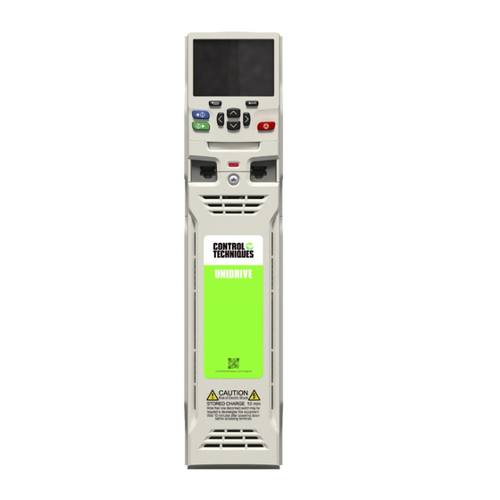
the heatsink of the Unidrive M600, M700, M800 size 3. The design of the
resistor is such that no thermal protection circuit is required, as the
device will fail safely under fault conditions. The in built software
overload protection is set-up at default to protect the braking resistor.
Contents of the box (1220-2752-01)
The following items are supplied in the box:
1 x 75 Ω Brake resistor assembly
•
•
2 x Cable crimps
•
1 x Installation sheet
3
Installation
Step 1: Removing the terminal covers
Figure 1-1 Removing the AC and DC terminal covers
•
To remove the terminal covers, undo the screw and remove the
covers in direction shown above (Figure 1-1).
•
The AC terminal cover (1) must be removed prior to the DC terminal
cover (2).
•
When replacing the terminal covers the screw should be tightened to
a maximum torque of 1 N m (0.7 lb ft).
Unidrive M600, M700, M800
Step 2: Removing the internal EMC filter
Figure 1-2 Removing the internal EMC filter
The internal EMC filter needs to be removed to establish brake resistor
electrical connections. To remove the internal EMC filter:
•
Loosen / remove the screw and nut as shown (1) and (2)
•
Lift away from securing points and then rotate away from the drive (3).
Ensure the screw and nut are replaced and re-tightened with a
maximum torque of 2 N m (1.47 lb ft).
Step 3: Preparing for installation
Figure 1-3 Removing the brake resistor bung
Remove the brake resistor bung from the hole in the chassis as shown
above. The cap at the closed end of the bung will need to be removed,
see Figure 1-4.
Figure 1-4 Removing the bung cap (end with lug on)
Remove the end of the bung with the lug on by piercing with a pair of
long nose pliers and pulling out in the direction shown above to leave a
hollow bung so that the cable can be routed through.
0478-0015-04
Advertisement

Summary of Contents for Control Techniques Unidrive M600
- Page 1 This braking resistor has been especially designed to be mounted within Ensure the screw and nut are replaced and re-tightened with a the heatsink of the Unidrive M600, M700, M800 size 3. The design of the maximum torque of 2 N m (1.47 lb ft).
- Page 2 Step 5: Establishing brake resistor electrical connections Figure 1-5 Inserting the brake resistor cable through the bung Figure 1-7 Electrical connections Heatsink mounted braking resitor Internal EMC filter • Feed the brake resistor bung on to the outer insulation of the brake resistor cable.


Need help?
Do you have a question about the Unidrive M600 and is the answer not in the manual?
Questions and answers