Table of Contents
Advertisement
Advertisement
Table of Contents

Summary of Contents for WERTHER INTERNATIONAL ALPHA 4040
- Page 1 ALPHA 4040 R.1......26/01/2016 C/16 WERTHER INTERNATIONAL S.p.A. Via F. BRUNELLESCHI, 12 42124 CADE’ (RE) - ITALY Telefono +39 / 0522 / 9431 (r.a.) - Telefax +39/ 0522 / 941997 WEB http://www.wertherint.com - E-mail sales@wertherint.com...
- Page 2 - 2 -...
- Page 3 INDEX 1.0 OVERVIEW 2.0 TECHNICAL FEATURES 2.1 MACHINE DRAWING 2.2 TECHNICAL DATA 2.3 APPLICATION RANGE 2.4 ACCESSORIES SUPPLIED 3.0 UNPACKING 4.0 POSITIONING 4.1 ANCHORING REQUIREMENTS 5.0 INSTALLATION 5.1 FLANGE ASSEMBLY 5.2 ELECTRICAL CONNECTION AND FUNCTIONING TESTS 5.3 OPERATING TESTS 6.0 INSTRUCIONS FOR USE 6.1 KEYBOARD 6.2 MAIN MENU 6.3 BALANCING...
-
Page 4: Technical Features
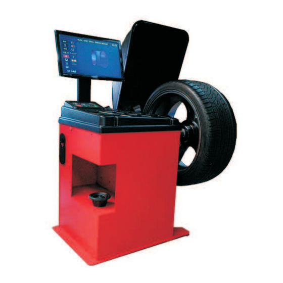
1.0 OVERVIEW The present instructions booklet is an integral part of the product. Carefully study the warnings and instructions contained in it. This information is important for safe use and maintenance. Conserve this booklet carefully for further consultation. THE MACHINE HAS BEEN DESIGNED TO OPERATE WITHIN THE LIMITS DESCRIBED IN THISBOOKLET AND IN ACCORDANCE WITH THE MAKER’S INSTRUCTIONS. - Page 5 2.1 MACHINE DRAWING indicating the main component parts for usage purposes LEGEND Main switch LCD Monitor Control panel Distance/diameter measuring gauge Sonar for width measurement Rubber feet spacer Wheel guard Quick nut Flange 10. Calibration tool 11. Centering cone holder 12.
-
Page 6: Technical Data
2.2 TECHNICAL DATA DIMENSIONS Max. height (wheel guard open) 1500 Depth (wheel guard closed) 1300 Width 1200 WEIGHT Net weight Gross weight ELECTRIC MOTOR Power supply 230V 1~50Hz Power 80 W Phases Balancing speed from 120 to 150 rpm at 50Hz Cycle time 8 sec Unbalance reading resolution... - Page 7 3.0 UNPACKING Once the packaging has been removed (Fig. 3) check to see that the machine is whole, ensuring there is no visible damage. In the case of doubts do not use the machine and contact professionally qualified personnel and/or your dealer. None of the packaging (plastic bags, pluriball, polyethylene, nails, staples, wood, etc.) must be left in the reach of children as they are potential sources of danger.
- Page 8 5.0 INSTALLATION 5.1 FLANGE ASSEMBLY Before mounting the flange, clean the conical surface of the spindle (1 Fig. 4) and the surface of the flange (2 Fig. 4). Place the flange on the spindle so the position of the markers (3 Fig. 4) on the spindle's snug and on the flange are aligned as shown in Fig.
-
Page 9: Operating Tests
5.3 OPERATING TESTS Pressing the START button (with the guard lowered), the mounted wheel must turn clockwise, seen from the right of the machine. Lowering the wheel guard the motor must start, lifting it during the spin the motor must stop. If rotation direction is wrong the machine stops immediately. - Page 10 6.0 INSTRUCIONS FOR USE 6.1 KEYBOARD Fig. 5 NOME FUNZIONE START Starting of measurement cycle Stopping a measurement cycle / imbalance correction STOP place movement Enter to program and sub-menu Enter to setting menu / exit from program and sub-menu Arrow UP Move cursor up Arrow DOWN...
- Page 11 ATTENTION: By pressing any button, the machine will beep as confirmation of the selection. WARNING: The wheel balancer has been designed and produced to balance car and light truck. Any other use of the machine is not allowed and may cause malfunction or breakdown.
- Page 12 6.3 BALANCING SCREEN All wheel parameter and balancing program settings are displayed in the BALANCING PROGRAM screen. Left bar (blue background) shows with icon the option, while the right bar (black background) shows current value stored in the machine. Fig. 7 Description Distance within wheel and the machine Wheel diameter...
- Page 13 6.4 MANUAL INPUT OF WHEEL PARAMETER Selecting with arrow UP and DOWN position 1,2 and 3 of Fig. 7, is possible to enter the values of distance, diameter and width of the rim that can be modified using the keys. 6.5 AUTOMATIC INPUT OF WHEEL PARAMETER The gauge arm automatically take the wheel data like distance and diameter.
- Page 14 6.6 USE OF GAUGE ARM FOR ALU WHEEL 6.6.1 WITH PROGRAM “ADJUSTER” ENABLE Extract the distance/diameter measuring gauge and position it according to point “B” of Fig. 8, without coming back to rest position select the location where to place the external weight point “C”...
- Page 15 6.6.2 WITH PROGRAM “EASY MODE” ENABLE Select required properly ALU program (prog 4 or 5), extract the gauge arm and posistioning the gauge in the point where you will apply the counterweight on the rim. If you are using prog. 4 the gauge must be in point “B”...
- Page 16 6.7 BALANCING PROGRAM SELECTION The use of different types of counterweights for the balancing of the several types of rims (steel or light alloy) produces differences between the nominal measurements set for the wheel to be balanced and the actual measures of the correction plans. To take account of these differences the machine can operate various balancing programs.
- Page 17 6.8 CHANGING OF THE THRESHOLD When a balancing spin finish, all the unbalance values below the selected threshold value will be displayed as “0”. The wheel balancer has four threshold values: 0, 2, 5 and 10 grams. To modify the threshold press button , Pressing either the keys the value of threshold will increase or decrease.
- Page 18 6.9 VISUALIZATION UNBALANCING WHEEL MODE It is possible to change the way that indicates the unbalance wheel value. There will be two different display visualization modes. 3D visualization: a 3D wheel is shown in the centre of the screen, where 2 painted dots are marked inside and outside position rim, indicates the current position of the unbalancing values.
-
Page 19: Balancing Mode
6.10 BALANCING MODE Before starting a wheel balancing cycle , the user can choose which balancing mode is properly, between passenger cars or motorcycles wheel. To have access to this function , select with the arrows UP and DOWN till the highlight indicate function n.7 at Fig.7 choose with keys. - Page 20 LOGO Fig. 12 – Hidden weight program - page selection first point In the left square it will shown the internal unbalancing value, in the central square it will shown the external unbalancing value. Rotating manually the wheel the arrows appear so rotate the wheel till the arrows and an acoustic signal advise the right external position.
- Page 21 LOGO Fig. 14 - Hidden weight program - balancing page with 2 external counterweights Rotate manually the wheel reaching right position with the arrows. The right points should be behind the spoke, previously stored., The 2 counterweights have to be applied using the distance/diameter gauge.
- Page 22 7.0 OPTIMIZATION When the unbalance measured on the wheel , is very high (e.g.: static unbalance > 50g) we suggest running the unbalance optimization procedure. The program allows the total unbalance of the wheel to be reduced compensating, when possible, the static unbalance of the tire with the one of the rim.
- Page 23 LOGO Fig. 16 – Optimization- Measure bare rim At the end of the spin , on the top of the screen will appear “Bare rim UNBALANCE” and on the bottom part the unbalancing value (Fig 17) ATTENTION: The unbalancing values which appear on this step has NOT to be correct, but it will be only as an help to determinate the state of art of the rim.
- Page 24 shaft of the wheel balancer as done in the previous step. Close the wheel guard and press START to spin the second measuring cycle. Fig. 18 - Optimization – measure tire and rim At the end of the spin, at the top side of the screen, will appear “PROFIT” and at the bottom side of the screen , will show the unbalance value which it will be possible to delete with the Optimization process.
- Page 25 LOGO Fig. 19 - Optimization – gain unbalance value 8.0 CALIBRATION The wheel balancer is calibrated in the factory prior to dispatch. During transport the values stored could have changed. It is therefore advisable to recalibrate the machine when installing it. It is also good practice to repeat calibration once a month.
- Page 26 Put on the flange the calibration tool and, with the cone on the outside, lock it with the quick nut, make sure that the red dot mark on the calibration tool will match with the one on the flange (Fig. 21).
- Page 27 8.2 USING A BALANCED WHEEL Mount on the machine an already balanced wheel (with steel rim), input the wheel data and apply on the external side of the wheel a 80 gr. Counterweight. Close the wheel cover and press START to proceed to the calibration spin, When the calibration cycle will end the display will show values 0 and 80 (79 is also accepted)and it means that the calibration of the machine was well done.
-
Page 28: Machine Setting
9.0 MACHINE SETTING From the setting machine menu it will be possible to modify some parameter as: SOUND BALANCING USG (SONAR DEVICE) CLOCK PRINTING MISC. All the parameters not enable or not provided , will be signed as “N/A” LOGO 9.1 SOUND VOLUME: It will be possible to adjust volume increase or dicrease, till to completely skip... - Page 29 AUTOSTART: with the keys it will be possible , setting the wheel spin mode. Setting ON mode, the wheel spin will be automatic when lowering the hood wheel; setting the OFF mode, the wheel spin will be manual , pressing START key, only if the wheel hood is lowering down.
-
Page 30: Troubleshooting
10.0 PROTECTION DEVICES AND TROUBLESHOOTING If the machine is not working properly, press the STOP key to stop the working cycle. When the machine has stopped rotating, disconnect it from the main and call the Technical Assistance Service 10.1 TROUBLESHOOTING These simple operations will help you find the simplest anomalies ANY AND ALL WORK ON THE ELECTRICAL SYSTEM, HOWEVER SMALL, MUST DEVE BE DONE BY PROFESSIONALLY QUALIFIED PERSONNEL! -
Page 31: Routine Maintenance
11.0 ROUTINE MAINTENANCE Cleaning and servicing the machine is a responsibility of the user. To guarantee machine efficiency and to ensure it always works properly it is essential to keep it clean and carry out periodical routine maintenance. The user must carry out the routine maintenance jobs in agreement with the manufacturer's instructions given below: Prior to any cleaning or maintenance work turn the machine off by means of the main switch and take the plug out of the power socket. - Page 32 13.0 PUTTING ASIDE AND SCRAPPING 13.1 PERIODS OF INACTIVITY Always take the plug out of the power socket whenever the machine is put aside temporarily or not being used. 13.2 FINAL SHELVING When the machine is not going to be used anymore it must be made unusable by removing the electrical power lead after taking the plug out of the socket.
-
Page 33: Technical Assistance And Spare Parts
14.0 INSTRUCTIONS FOR THE CORRECT MANAGMENT OF WASTE MATERIAL FORM ELECTRIC AND ELECTRONIC DEVICES (WEEE) UNDER THE 2002/96/CE AND 2003/108/CE DIRECTIVE · It is obligatory by law not dispose of WEEE as regular urban trash. · It is also obligatory by law to collect each type of waste material separately and take it to dedicated recycling depots according to the indications provided by the manufactures of the devices. - Page 34 NOTE: …......................................…......................................…......................................…......................................…......................................…......................................…......................................…......................................…......................................…......................................…......................................…......................................…......................................…......................................…......................................…......................................- 34 -...
-
Page 35: Exploded View
EXPLODED VIEW - 35 -... - Page 36 CODE DESCRIPTION 1 06,02,045 KEYBOARD 2 P-04.00.03 WEIGHT HOOD 3 PS.MINI2 POWER SUPPLY BOARD 4 06,01,115 TRANSFORMER 5 P.PG16 CPU BOARD 6 05,05,009 MAIN POWER SWITCH 7 05,09,011 FUSE 8 05,09,131P MONITOR LCD 9 05,09,061 SPEAKER 10 P1-09,00,01 WHEEL HOOD 11 05,07,008 EXT.
- Page 37 Dichiarazione di conformità - Déclaration de conformité Declaration of Conformity - Konformitätserklärung Declaración de conformidad - Overensstemmelseserklæring Överensstämmande intyg - EG-Conformiteitsverklaring WERTHER INTERNATIONAL S.p.A. Via F.Brunelleschi, 12 42124 CADE’ (Reggio Emilia) Italy Tel.+39/0522/9431 (r.a.) Fax +39/0522/941997 con la presente dichiara che la equilibratrice Com a presente, declaramos que a máquina balanceadora...
Need help?
Do you have a question about the ALPHA 4040 and is the answer not in the manual?
Questions and answers
unde **** sa gasesc tastatura
If the WERTHER INTERNATIONAL ALPHA 4040 keyboard is defective, it can be replaced. Check the correct connection between the keyboard and the PC-Board first. If the keyboard is still not working, replace it.
This answer is automatically generated
este o problema **** meniul tastatura nu functioneaza tasta minus pentru masurarea latimei anvelope sau jantei
The minus key may not be working on the WERTHER INTERNATIONAL ALPHA 4040 for measuring tire or rim width because the width parameter is automatically acquired by the sonar positioned on the side of the wheel cover. The machine does not require manual input for this measurement, as the width is stored in memory when the cover is closed to start the measuring cycle.
This answer is automatically generated
nu funtioneaza tasta - minus
The minus key on the WERTHER INTERNATIONAL ALPHA 4040 may not be working due to a connection problem between the keyboard and the PC-Board or a defective keyboard. To fix this, check the connection between the keyboard and the PC-Board, and if necessary, replace the keyboard or the PC-Board.
This answer is automatically generated
@Mr. Anderson