
Related Manuals for Ruwac industriesauger NA 7-26

Summary of Contents for Ruwac industriesauger NA 7-26
- Page 1 Instruction Manual Wet separators Type NA 7-26 Translation of the original instruction manual Issued: 26.04.2018...
- Page 2 RUWAC Industriesauger GmbH Westhoyeler Str. 25 D - 49328 Melle, Germany Tel: +49 (0) 5226-9830-0 www.ruwac.de ruwac@ruwac.de Osnabrück Law Courts – HRB 112 VAT no: DE 811188960 Managing Directors: Axel Runge, Thomas Runge Copyright © Copyright RUWAC GmbH. All rights reserved.
-
Page 3: Table Of Contents
NA 7-26 Safety devices ........ - Page 4 Attaching / detaching the vacuum hose............31 Establishing potential equalisation (optional) .
- Page 5 Type NA 7-26 ........
-
Page 6: General
(maintenance, inspection, repairs) of the machine must carefully read and observe this instruction manual. RUWAC Industriesauger GmbH assumes no liability for damage or malfunctions caused as a result of a failure to follow the information contained in the instruction manual! -
Page 7: Symbols And Displays
General Symbols and Displays 1.4.1 Hazard levels in Safety Precautions DANGER Indication of immediate danger which could result in death or serious injury if appropriate measures are not taken. WARNING Indication of possible danger which could result in death or serious injury if appropriate measures are not taken. -
Page 8: Pictograms In The Instruction Manual
General 1.4.2 Pictograms in the Instruction manual The following symbols and pictograms may occur in this documentation: This symbol appears at all safety precautions in this documentation. Failure to observe instructions marked with this symbol can lead to injury or death. Make sure you observe this information and be particularly careful in these situations. -
Page 9: Safety
Safety Safety Intended use Vacuum medium The wet separator can be used for vacuuming up dry, wet, hot, smouldering and explosive media which may be either fine or coarse, and for feeding back filtered air into the working area. The wet separator is classified according to the dust classes specified in IEC / EN 60335-2-69 and may be used to vacuum up only dusts within the respective workplace limit values for the dust concerned. -
Page 10: Improper Use
Safety Improper use No changes, attachments or conversions that may influence safety may be made to the wet separator. This also applies to installing and adjusting safety equipment and valves. The wet separator must not be located in areas that may have a potentially explosive atmosphere. -
Page 11: Notices On The Machine
Safety Notices on the machine The stickers shown below are affixed to the machine. If they are damaged or illegible, they must be replaced. The rating plate is affixed to the housing. Replace the sticker if it is damaged or illegible. CE mark [CE, abbreviation for Conformité... - Page 12 Safety The warning instruction alongside is attached to the wet separator. Warnung! Unplug both the electrical plugs from the mains before working on Vor Arbeiten im Innern des Gerätes beide Anschluss-Stecker der Antriebseinheit abziehen the inner parts of the wet separator. Warning! Disconnect both connection plugs of the drive unit before working inside the vacuum...
-
Page 13: Dust Classes
Safety Dust classes Wet separators are divided into dust classes: L = Low hazard The wet separator is suitable for vacuuming up dusts that are dry and non-hazardous to health and that have a workplace exposure limit (WEL) of > 1 mg/m ... -
Page 14: Personnel Requirements
Safety Personnel requirements Only personnel trained to use the wet separator and familiar with it may operate it. Staff responsibility in terms of operation, set-up and performance of maintenance procedures must be clearly defined. The operator must immediately report any safety critical faults which occur on the wet separator to the person responsible for safety. -
Page 15: Na 7-26 Safety Devices
Safety 2.7.1 Safety devices NA 7-26 Item Name Liquid container unlocking lever Liquid container level sensor Unfiltered gas connection locking slide Moisture separator Filter cartridges Degasification valve Vent Controls Fresh air filter H (behind the ventilation plate) Castors with parking brake (optional additional... -
Page 16: Residual Risks
Safety Residual risks 2.8.1 Installation and storage DANGER Evolution of flammable gases On finishing work, always store or place the wet separator in a well-ventilated area. Depending on the materials vacuumed up, flammable gases such as hydrogen may be evolved. ... -
Page 17: Work On Electrical Components
Safety 2.8.2 Work on electrical components Unplug at the mains before performing maintenance work. Improper work on live components could result in electrocution with loss of life. All covers, housings etc. related to electrical components may only be opened by authorised qualified electricians for the purpose of carrying out maintenance and repair work. -
Page 18: Setup And Function
Setup and function Setup and function Description The wet separator is suitable for vacuuming up dry, wet, hot, smouldering and explosive media which may be either fine or coarse, and for feeding back filtered air into the working area. The dusty medium is vacuumed up via the unfiltered gas connection (3) and the dip tube (1) into the sealing liquid of the liquid container (2). -
Page 19: Type
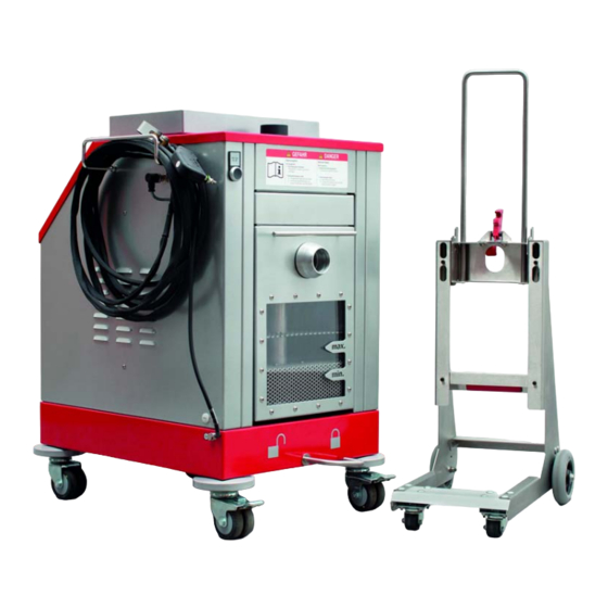
Controls Ventilation plate with fresh air filter Drive unit Level sensor Optional additional equipment Various items of additional equipment is available for the NA 7-26; these are shown below. Additional equipment: Wheel set with castors and parking brake. Page 19... - Page 20 Setup and function Additional equipment: Wheel set with wall spacer rollers. Additional equipment: Push handle. Additional equipment: Cable holder. Page 20...
- Page 21 Setup and function Additional equipment: Hose holder, left hand. Additional equipment: Hose holder, right hand. Additional equipment: Earthing Earthing clip for the vacuum hose Additional equipment: Potential equalisation OPTIONAL: With monitoring function “Potential equalisation connected” With angled socket ...
- Page 22 Setup and function Additional equipment: Plugs for different mains sockets. Additional equipment: Exhaust air connection. Additional equipment: Trolley for liquid container. Page 22...
-
Page 23: Description Of Components
Setup and function Description of components Drive unit The partial vacuum in the wet separator is generated by 2 single-phase AC blowers. Liquid container The liquid container (8) (max. capacity 7 ltr) is located at the rear of the wet separator. The liquid container can be removed for filling and emptying. - Page 24 Setup and function Moisture separator The housing of the moisture separator is located on the liquid container. The moisture separator separates small droplets of liquid and residual particles from the vacuumed up medium. The moisture separator can be removed for cleaning. Filter 3 filter cartridges are located above the moisture separator.
- Page 25 Setup and function Degasification valve The degasification valve is fitted on the cover of the wet separator. Depending on the medium that is vacuumed up, flammable gases may be evolved in the wet separator. These are discharged into the atmosphere via the degasification valve. During vacuum operation the spring-loaded degasification valve is kept closed by the partial vacuum.
- Page 26 Setup and function Potential equalisation angled socket or earthing clamp (optional) By means of the angled socket or earthing clamp the potential equalisation cable the wet separator is electrically bonded to the working environment or the machine that is being cleaned. Earthing clip (optional) By means of the earthing clip the hose connection spigot of the vacuum hose is electrically bonded to the wet separator.
-
Page 27: Technical Data
Technical Data Technical Data NA7- 26 Motor power (kW) 2.6 / 2.89 Voltage (V) 230 / 240 Frequency (Hz) 50 / 60 Current consumption (A) 11.9 / 12.3 Width (mm) Length (mm) Vacuum (mbar) -160/ short periods -210 Air flow rate (m (measured with a 3 m vacuum hose) Sound pressure level (dB(A)) Weight (kg) -
Page 28: Transport
Transport Transport DANGER Risk of injury if struck or crushed while lifting or transporting the wet separator. Transport must only be performed by appropriately instructed personnel. Always stay a safe distance from the components whilst they are being lifted. ... -
Page 29: Installation
Installation Installation Safety precautions for Installation The operating company is responsible for ensuring that the floor at the installation site is sufficiently stable with an adequate load capacity. See section “Technical Data” on page 27 for data on weights. Electrical connection DANGER Risk due to electric shock! ... -
Page 30: Commissioning
Commissioning Commissioning Filling the liquid container 1. Move the unlocking lever of the liquid container to the left. 2. Using the handle, pull the liquid container out of the wet separator. Grip the left and right grip recesses with both hands and remove the container. -
Page 31: Attaching / Detaching The Vacuum Hose
Commissioning 4. Fill the liquid container with suitable sealing liquid. The swirl filter can be removed to facilitate filling. If the swirl filter is removed, it must be inserted again after the liquid container has been filled. 5. Check the fill level at the viewing window of the liquid container. -
Page 32: Establishing Potential Equalisation (Optional)
Commissioning Establishing potential equalisation (optional) 1. Attach the earthing clip to the metal hose connection spigot of the vacuum hose. 2. Connect the handle of the potential equalisation cable to the potential equalisation point in the working environment or on the working machine. -
Page 33: Electrical Connection
Commissioning Electrical connection DANGER Risk due to electric shock! Improper work on live components could result in electrocution with loss of life. All covers, housings etc. of electrical components may be opened only by authorised qualified electricians for the purpose of carrying out maintenance work. -
Page 34: Connecting The Vacuum Accessories
Commissioning Connecting the vacuum accessories CAUTION Build-up of electrostatic charge on parts of the vacuum system Use only conductive parts on the vacuum system. Important The accessories may vary depending on the scope of supply. Many parts of the vacuum system require the adapter shown. 1. -
Page 35: Operation
Operation Operation DANGER Risk due to electric shock! If a damaged power supply cable is connected there is a risk of fatal accidents due to electric shock. Before each occasion the wet separator is used, a check must be made to ensure the power supply cable is in good condition. -
Page 36: Applying / Releasing The Parking Brake (Optional)
Operation Applying / releasing the parking brake (optional) 1. To stop the wet separator from moving, use the toe of your shoe to press down the parking brakes (optional) on the castors. 2. The parking brake is released the by pressing with the toe of the shoe (see arrow). -
Page 37: Topping Up The Sealing Liquid
Operation Topping up the sealing liquid 1. Lock the parking brake, see “Applying / releasing the parking brake (optional)” on page 36. 2. Pull the vacuum hose off the unfiltered gas connection, see “Attaching / detaching the vacuum hose” on page 31. 3. -
Page 38: Checking The Function Of The Degasification Valve
Operation Checking the function of the degasification valve DANGER Evolution of flammable gases On finishing vacuum operations, always store or place the wet separator in a well-ventilated area, since depending on the material being vacuumed up, hydrogen gas can be evolved. -
Page 39: Removing The Liquid Container With Trolley (Optional)
Operation Removing the liquid container with trolley (optional) 1. Lock the parking brake, see “Applying / releasing the parking brake (optional)” on page 36. 2. Pull the vacuum hose off the unfiltered gas connection, see “Attaching / detaching the vacuum hose” on page 31. 3. -
Page 40: Cleaning The Liquid Container And The Moisture Separator
Operation Cleaning the liquid container and the moisture separator Important The liquid container must be cleaned at the end of every shift / at the end of every work period. 1. Lock the parking brake, see “Applying / releasing the parking brake (optional)”... - Page 41 Operation 7. Remove the swirl filter including the dip tube. 8. Empty the liquid container. Dispose of the contents of the liquid container in an environmentally responsible way. 9. Clean the liquid container using a water jet. Dispose of the resulting waste water in an environmentally responsible way.
- Page 42 Operation 10. Use a soft cloth the clean the viewing window of the liquid container. 11. Use a soft cloth the clean the window of the capacitive fill level monitoring in the liquid container. 12. Fill the liquid container with a suitable sealing liquid, see “Filling the liquid container”...
-
Page 43: Fault Diagnosis
Fault diagnosis Fault diagnosis Safety precautions when troubleshooting DANGER Risk due to electric shock! Improper work on live components could result in electrocution with loss of life. Troubleshooting may be performed only by trained professionals. All covers, housings etc. related to electrical components may be opened only by authorised qualified electricians for the purpose of carrying out maintenance and repair work. -
Page 44: Causes Of Faults And Corrective Action
Fault diagnosis Causes of faults and corrective action Fault Cause of fault Corrective action The wet separator shuts down. Level has fallen below the minimum Check the fill level and if necessary top up with fill level. Display <Low level> in suitable sealing liquid, see page 37. - Page 45 Fault diagnosis Fault Cause of fault Corrective action Warning <The service interval of The blower has reached a running time Replacement of the fresh air filter is nearly due. the fresh air filter is nearly due>. of 40 hours. Warning <The service interval of The blower has reached a running time Replacement of the fresh air filter is due.
-
Page 46: 10 Controls
Controls 10 Controls 10.1 Overview of the operating panel / display panel Displays and membrane pushbuttons on the display panel / operating panel 1. Membrane pushbutton <Switch on> 2. Membrane pushbutton <Menu> 3. Display <Potential equalisation lost> 4. Display <Motor protection triggered> (not assigned) 5. -
Page 47: Calling Up The Main Menu
Controls → The message <Is there enough water in the tank?> appears in the <Display> (8). 2. Check the fill level and press the membrane pushbutton <Enter> (10). (If the membrane pushbutton <Enter> (10) is not pressed within 5 s, the message clears anyway.) →... -
Page 48: Setting The Language
Controls 10.4 Setting the language 1. Press the membrane pushbutton <Menu> (2). 2. Press the membrane pushbutton <Navigation downwards> (12) until the cursor is at <Language>. Then press the membrane pushbutton <Enter> (12). → The various language options are displayed. 3. -
Page 49: Acknowledging Alarm Messages
Controls 10.7 Acknowledging alarm messages If an error occurs during vacuuming operations, an appropriate alarm message will be shown in the display (8). The alarm message alternates with <Device error> in the display. If an error that has not been resolved is present, the membrane pushbutton <Switch off>... -
Page 50: Overview Of Alarm Messages / Warning Messages
Controls 10.8 Overview of alarm messages / warning messages Type of signal Message text Status Acknowledge Solution Alarm message <Low level> (the wet The liquid level in the Top up the sealing liquid separator shuts itself liquid container is below down or cannot be the minimum. - Page 51 Controls Type of signal Message text Status Acknowledge Solution Warning message <The service interval of The fresh air filter has Replacement of the (appears only after the the fresh air filter is reached the maximum fresh air filter is due. device has been overdue>...
-
Page 52: 11 Maintenance
Maintenance 11 Maintenance The RUWAC wet separator is low-maintenance for the operating company. Nevertheless, the operating company must ensure that the daily checks are performed, and that the wet separator is used carefully and serviced. Servicing work may be performed only by capable persons authorised by RUWAC. -
Page 53: Daily Checks
Maintenance 11.2 Daily checks Before the wet separator is used the following functions must be checked and any necessary work performed: Functional test of degasification valve. Fill the liquid container with a suitable sealing liquid. Check the fill level of the liquid container (do this also at regular intervals during operation). -
Page 54: 12 Decommissioning And Disposal
Decommissioning and disposal 12 Decommissioning and disposal 12.1 Decommissioning At decommissioning, comply with all the basic safety precautions in section “Safety” on page 9. Before starting to dismantle the wet separator, disconnect it from the mains. The vacuum hose must be taken off and the wet separator emptied and cleaned. -
Page 55: 13 Appendix
Spare part inventory In order to achieve the shortest breaks in operations in the event of a defect, RUWAC Industriesauger GmbH recommends that a stock is maintained of the necessary spare parts. The necessary spare parts are those parts of the machine that if they fail can cause a complete loss of service by the wet separator. -
Page 56: Spare Parts And Wearing Parts
To ensure quick processing of your questions and orders, indicate the serial number as shown on the rating plate. This will enable us to process your enquiries more quickly. 13.2.1 Type NA 7-26 Item Description Part no. Filter cartridge, 0.1 m... -
Page 57: Associated Documents
Appendix 13.3 Associated documents 13.3.1 Declaration of Conformity EU-Konformitätserklärung EU Declaration of Conformity Bevollmächtigter für die Zusammenstellung der relevanten technischen Unterlagen The person authorised to compile the relevant technical documentation Thomas Welkener Hiermit erklären wir, dass die nachstehend beschriebene Maschine / Anlage Herewith we declare, that the machinery described below Produktbezeichnung / product denomination: Industriesauger/... - Page 58 Acknowledging alarm messages .............49 Air flow rate ..................27 Ambient conditions ................16 Areas that may have a potentially explosive atmosphere....10 Calling up the main menu ..............47 CE mark ...................11 Checking the degasification valve ...........38 Cleaning ...................17 Cleaning the liquid container ............40 Commissioning ................30 Component ..................23 Contact data ..................6...
- Page 59 Improper use ..................10 Instruction manual ................6 Intended use ..................9 Length ....................27 Level sensor ................15, 19 Liquid container ................19, 23 Liquid container unlocking lever ............19 Liquid volume ...................27 Maintenance ..................52 Maintenance contract ...............52 Moisture separator ..............15, 23 Motor power ..................27 Moving parts ..................17 Notices .....................11 Operating panel / display panel ............24 Operating personnel ................14...
- Page 60 Swirl filter ...................19, 23 Switching on the wet separator ............46 Symbols .....................8 Taking off the moisture separator ............30 Target group ..................6 Transport ..................28 Type ....................19 Unfiltered gas connection locking slide ..........19 Unfiltered gas connection: ............19, 27 Unlocking lever ................15 Vacuum ....................27 Vacuum medium ................9 Vent ...................15, 19 Voltage .....................27...
- Page 61 Notes Page 61...
- Page 62 Notes Page 62...
- Page 63 Notes Page 63...
- Page 64 76674 - en...
Need help?
Do you have a question about the NA 7-26 and is the answer not in the manual?
Questions and answers