Table of Contents
Advertisement
Quick Links
Advertisement
Table of Contents

Summary of Contents for Ironton 61454
- Page 1 Angle Grinder Holder Owner’s Manual WARNING: Read carefully and understand all ASSEMBLY AND OPERATION INSTRUCTIONS before operating. Failure to follow the safety rules and other basic safety precautions may result in serious personal injury. Item #61454 READ & SAVE THESE INSTRUCTIONS...
- Page 2 Thank you very much for choosing an Ironton™ product! For future reference, please complete the owner’s record below: Serial Number/Lot Date Code: ________________________________ Purchase Date: ____________________________________________ Save the receipt, warranty, and this manual. It is important that you read the entire manual to become familiar with this product before you begin using it.
-
Page 3: Table Of Contents
Table of Contents Intended Use ............................4 Packaging Contents ..........................4 Technical Specifications ........................4 Important Safety Information ....................... 4 Specific Operation Warnings ....................... 6 Main Parts of Holder ..........................6 Assembly Instructions .......................... 6 Before Each Use ..........................11 Operating Instructions ........................ -
Page 4: Intended Use
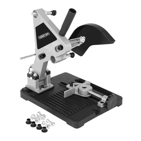
Intended Use The Ironton Angle Grinder Holder is designed to hold most common 4 1/2 inch or 5 inch grinders with side handles without modifications. It turns your portable angle grinder into a metal-cutting chop saw which makes it a perfect tool for cutting tubing, bar stock, and rebar. - Page 5 Cluttered, wet, or dark work areas can result in injury. Using the product in confined work areas may put you dangerously close to cutting tools and rotating parts. Do not use the product where there is a risk of causing a fire or an explosion; e.g., in the presence of flammable liquids, gases, or dust.
-
Page 6: Specific Operation Warnings
the power switch is dangerous and must be repaired by an authorized service representative before using. Disconnect the power/air supply from the product and place the switch in the locked or off position before making any adjustments, changing accessories, or storing the tool. Such preventive safety measures reduce the risk of starting the tool accidentally. - Page 7 Assembly Steps 1. Unscrew the two bolts on the jaw clamps and use these two bolts to attach the jaw clamps on the stand. Finger-tighten the two bolts. Do not fully tighten them as you may need to adjust the distance between these two jaw clamps according to your angle grinder size (images 2 and 3).
- Page 8 3. Assemble the stand on the base by using the two bolts (A). Finger-tighten these two bolts (image 4. Insert the M10 x 68mm bolt (with nut) (B) and M10 x 50mm bolt (with nut) (C) into the two holes on the stand.
- Page 9 6. Place the head of your angle grinder between the two jaw clamps. You may need to adjust the distance between the two jaw clamps according to the size of the angle grinder head (image 8). Use the most appropriate bolts you chose to attach the angle grinder head on the jaw clamps. Use an adjustable wrench (not included) to fully tighten the bolts.
- Page 10 10. Loosen the nut on the handle and assemble the handle on the stand (image 12). 11. Unscrew the locking nut on the lever (image 13). 12. Insert the lever into the hole on the safety guard and screw the locking nut on and fully tighten it. Fully tighten the other nut on the lever (image 14).
-
Page 11: Before Each Use
15. Reassemble bolt D on the stand and fully tighten using an adjustable wrench (not included) (image 17). Before Each Use ⚠WARNING Check for loose or damaged parts and replace as needed. Make sure the holder is in good working condition. -
Page 12: After Each Use
1. Adjust the holder to the desired angle and tighten the object on the base. 2. Connect to power. Hold the handle (19) firmly and slowly push down the angle grinder. After Each Use ⚠WARNING Store the holder in a dry and clean place. ... -
Page 13: Maintenance
Maintenance Maintain the holder by adopting a program of conscientious repair and maintenance in accordance with the following recommended procedures. It is recommended that the general condition of any tool be examined before it is used. Keep your tool in good repair. Keep handles dry, clean, and free from oil and grease. -
Page 14: Parts Diagram
Parts Diagram Page 14 of 18... -
Page 15: Parts List
Parts List Part Number Part Description Quantity Base Bracket Hex Screw (M8 x 14) Spindle (10x59) Flange Stand Spring Washer (¢14×¢6.3×1.5) Hex Screw (M6×16) Clip Hex Nut (M5) Bolt (M5×16) Hex Screw (M8×30) Hex Screw (M8×25) Hex Nut (M10) Bolt Lever Hex Nut (M6) Handle... -
Page 16: Replacement Parts
Replacement Parts For replacement parts and technical questions, please call Customer Service at 1-800-222-5381. Not all product components are available for replacement. The illustrations provided are a convenient reference to the location and position of parts in the assembly sequence. ... -
Page 17: Limited Warranty
Northern Tool and Equipment Company, Inc. ("We'' or ''Us'') warrants to the original purchaser only (''You'' or ''Your'') that the Ironton product purchased will be free from material defects in both materials and workmanship, normal wear and tear excepted, for a period of one year from date of purchase. - Page 18 Distributed by: Northern Tool & Equipment Company, Inc. Burnsville, Minnesota 55306 www.northerntool.com Made in China Page 18 of 18...
Need help?
Do you have a question about the 61454 and is the answer not in the manual?
Questions and answers