
Summary of Contents for SuperFlow SF- 902S
- Page 1 Operator Manual Pub. No.: 191204 Rev.: 2 April 2020 Original Instructions www.SuperFlow.com SF- 902S Engine Dynamometer...
- Page 2 Copyright 2018 by SuperFlow Dynamometers & Flowbenches. All rights reserved. No part of this publication may be reproduced, transcribed, or translated by any means without the prior written permission of SuperFlow Dynamometers & Flowbenches, N60 W22700 Silver Spring Drive, Sussex, WI 53089 USA.
-
Page 3: Table Of Contents
Table of Contents Introduction ........................1 About This Manual ....................1 Target Audience .....................1 Product Features ....................1 Principles of Water Brake Dynamometer Operation ..........2 Safety Guidelines ......................3 At Installation ......................5 During Operation ....................5 Lockout/Tagout Procedures ...................6 System Overview ......................7 Overview ........................7 Dynamometer ......................8 SF-902S .........................8 Data Acquisition ....................11 Components ......................11... - Page 4 Table of Contents Electrical Safety ....................42 Fuses ........................42 Safety Procedures ....................43 Test Preparation ....................44 Mounting the Front of the Engine .................44 Mounting the Engine ....................44 Dyno Shaft Connection ..................45 Engine Water Cooling System ................46 Throttle System ....................47 Sensor Connections .....................48 Stand Connections ....................48 Engine Connections .....................48 Running an Automated Test .................49...
-
Page 5: Introduction
1.0 Introduction 1.1 About This Manual This manual is provided as a reference to explain the operation of the SuperFlow dynamometer system as used on an engine test system and also covers the operation and maintenance of the SF-902S engine test stand. -
Page 6: Principles Of Water Brake Dynamometer Operation
1.0 Introduction 1.4 Principles of Water Brake Dynamometer Operation An engine dynamometer (dyno) is a service tool that allows the operator to safely place a controlled load on an engine. A loaded engine test is the only method of verifying engine capability. With the use of a dyno, an engine can be properly operated throughout its power range without being placed into service. -
Page 7: Safety Guidelines
2.0 Safety Guidelines Safety is the most important consideration when operating any dynamometer system. Operators and service personnel should read this manual and become familiar with its content before attempting to operate this machine or to perform service or maintenance to it. Familiarization with this manual will minimize the possibility of accidents or injuries. - Page 8 2.0 Safety Guidelines The following universal warning decals can be found in the appropriate locations on your equipment. A description of each warning decal is provided below. In addition, these symbols will appear throughout the manual in sections where these hazards may be encountered. Refer to Manual Electric Shock •...
-
Page 9: At Installation
2.0 Safety Guidelines 2.1 At Installation WARNING CAUTION • Take care that the dynamometer is not dropped • Do NOT lift the dynamometer by the input or set down sharply. This could cause damage shaft. This may damage the dynamometer and to the bearing races and brinelling of the void its warranty. -
Page 10: Lockout/Tagout Procedures
2.0 Safety Guidelines CAUTION WARNING • Personnel should NOT be in the test cell during • Inspect the equipment monthly to ensure that operation and observation areas MUST be there are no broken or worn parts which could constructed to protect personnel. cause injury to personnel or damage to the •... -
Page 11: System Overview
3.0 System Overview 3.1 Overview The WinDyn dynamometer software system is an instrumentation package designed for complete test control and data acquisition of an engine or chassis dynamometer. Typical applications include: • Research and development (R&D) • Performance testing • Durability and quality control testing •... -
Page 12: Dynamometer
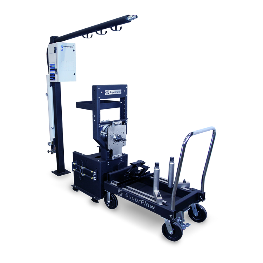
3.0 System Overview 3.2 Dynamometer The dynamometer stand provides all of the connections from the sensors to the data acquisition system and the mount for the power absorber. SF-902S The SF-902S system utilizes a floor-mounted absorber stand and a roll-around engine docking cart to maximize test efficiency in high-volume environments. - Page 13 3.0 System Overview Integrated boom routes water from the engine to the cooling tower and organizes transducer cables. Boom mounted sensor box. Large tool tray. SF-871 Engine Power Absorption Unit Versatile docking engine cart. Engine Cooling Column. Rugged, high torque power absorber.
- Page 14 3.0 System Overview Water Quality The quality of the water used in a dynamometer affects absorber and water pump operation. Contamination, salt water, or water with a high mineral count can reduce their life and increase maintenance costs. The load control valve and water seals in the absorber can quickly deteriorate with bad water.
-
Page 15: Data Acquisition
3.0 System Overview 3.3 Data Acquisition Components A WinDyn data acquisition system consists of at least two components. They are the sensor system and the computer system. NOTE: Additional options and accessories that can be added to the system are described later in this chapter. -
Page 16: The Computer System
The WinDyn instrumentation system requires a dedicated, stable electrical power source for proper operation. SuperFlow recommends using an Uninterruptible Power Supply (UPS) that has a minimum rating of 750 VA or a high-quality surge suppressor for the sensor box and computer. This may protect the electronics from damage in the event of a power surge and keep the engine running if the power goes out. -
Page 17: Sensor Panel Modules
Servo valve connection (engine dynos) • Electronic throttle connection • Auxiliary voltage sensor inputs • Fuel turbine frequency inputs • Auxiliary control outputs Figure 3.5: Sensor Interconnect Panel • Digital input and output connections NOTE: SuperFlow recommends capping or covering any unused AMP connector. - Page 18 3.0 System Overview Thermocouple Input Panel The thermocouple panel provides 16 channels for temperature measurements on the test device. • 16 channels per panel • Type K, (grounded or ungrounded) • Type K thermocouple range, -454° to 2,300°F (–270° to 1260°C), linearized •...
- Page 19 3.0 System Overview Engine Control Panel The engine control panel has five outputs electrically controlled by console switches or by programmed test profiles. Four outputs provide 12V switched DC power for ignition, starter, fuel pump, and auxiliary control. • Internal, automatic reset, 50A thermal breaker on input source, automatic reset, 10-amp polyfuse on ignition output;...
-
Page 20: Accessories And Options
3.0 System Overview 3.4 Accessories and Options A wide selection of additional sensors, adapters, and engine accessories are available. Contact SuperFlow Sales or Customer Service for additional details. Analog Voltage Input Panel The analog voltage panel is an optional accessory that provides up to eight channels of voltage measurements on the test device. - Page 21 3.0 System Overview Fuel System The fuel system consists of a high performance fuel pump and fuel regulators to provide two measured and regulated engine fuel channels. The system is rated up to 800 lbs/hr total delivery with both channels used. •...
- Page 22 3.0 System Overview Oil Coolers A constant engine temperature is vital in dynamometer testing, especially during endurance tests. Figure 3.15 shows a multi-pass heat exchanger with the water inlet controlled by a mechanical thermostat valve. It can be mounted on the absorber stand, the engine cart, or in an alternative convenient location. Figure 3.15: Oil Cooler...
- Page 23 3.0 System Overview Engine Cooling Towers The cooling tower replaces the radiator for water-cooled engines (see Figure 3.16). The thermostat on the cooling tower can be set to control the engine water temperature to a specific setting. The SF-902S CT600 cooling tower is mounted on the boom support assembly.
- Page 24 3.0 System Overview Volumetric Blow-by The JTEC VF563 series flow meter provides exceptional accuracy. The sensor measures blow by in Actual cubic feet per minute (ACFM) units. Figure 3.17: Blow-by Sensor...
- Page 25 3.0 System Overview SuperStart SuperFlow’s SuperStart option positions the starter on the dynamometer, saving setup time by eliminating the need for a starter on the motor. The SuperStart lets you start engines without starter bosses such as sprint car engines.
-
Page 26: Installation
4.0 Installation 4.1 Location Location and positioning of the dynamometer is an important factor in creating a functional, easy-to-use test cell. The following guidelines have been provided to assist in positioning your dynamometer: • The engine dynamometer test cell should be located in an area that is easily accessible from the rebuild area. -
Page 27: Plumbing Diagram
4.0 Installation 4.2 Plumbing Diagram... -
Page 28: Unpacking
1. Inspect the crates and boxes for external damage. Be sure to check underneath the crate for possible forklift damage. Report any damage to the shipping company and SuperFlow Customer Service. 2. Remove all components and accessories from the crates or boxes. -
Page 29: Absorber Stand
4.0 Installation 4.5 Absorber Stand The SF-902S absorber stand can be installed stand-alone, fixed in place, or used as a combined unit with the engine cart. 1. Position the SF-902S absorber stand in a suitable location in the test cell leaving enough space at the front of the stand for the engine cart, the rear of the stand for the exhaust system, and the sides for access to the engine. - Page 30 4.0 Installation 7. Locate a small (1/4”) black nylon line on the absorber stand right-side channel with a hose fitting on the end. This is the supply line for the dyno prime, absorber seal feed, and hydraulic throttle. Attach the hose to the supply fitting on the rear left corner of the tank (Figure 4.2).
- Page 31 4.0 Installation 10. Install the exhaust heat shields on each side and on the rear of the stand (Figure 4.4). Figure 4.4 Exhaust Heat Shield 11. Place the water tank cover in position on top of the tank (this cover requires periodic removal to access inside the tank for maintenance).
-
Page 32: Sensor Box
4.0 Installation 4.6 Sensor Box Mount the sensor box on the absorber stand boom. The absorber stand mount makes the sensor connections to the engine easy. A power cord attaches to the bottom of the box. Electrical power for the sensor box should come from a dedicated, protected line. -
Page 33: Cooling Towers
4.0 Installation 4.7 Cooling Towers FROM ENGINE (HOT) The engine cooling tower is mounted on the boom support. The two water hoses (supply and drain) must be connected as shown in Figure 4.6. A thermocouple should be installed on the cooling tower and connected to the Data Acquisition System to monitor and record the cooling temperature with WinDyn. - Page 34 4.0 Installation Figure 4.6 CT700P Pressurized Cooling Tower...
-
Page 35: Computer System
The thumb-drive is only necessary if you must recover or reinstall the Windyn software. Windyn software is also installed in a SuperFlow System Recovery folder on the computers hard drive, along with manuals and other pertinent documentation. -
Page 36: System Interconnect Panel
Figure 4.8 System Interconnect Panel Air 1 SuperFlow airflow measurement turbines are connected to the sensor box system interconnect panel. Use cable 1200A-2044 to connect to the red receptacle labeled Air 1. Calibration tables for each flow turbine are entered in the configuration file. Other TTL or MAG frequency devices can be connected here as well but require modification to the definition of channel 7. - Page 37 4.0 Installation Tach/Freq A second SuperFlow air turbine can be connected to the yellow receptacle labeled Tach/Freq if desired. Calibration tables for each flow turbine are entered in the configuration file. Other TTL or MAG frequency devices can be connected here as well but require modification to the definition of channel 12.
- Page 38 4.0 Installation Electrical Diagram ...
-
Page 39: Sensor Interconnect Panel
4.0 Installation Sensor Interconnect Panel The sensor interconnect panel (Figure 4.10) provides connections to the primary sensors and controllers on the dynamometer. Figure 4.10 Sensor Interconnect Panel Load Cell 1 Plug the load cell (strain gauge) cable into panel connector marked Load Cell 1. Tach Plug the tach sensor cable into the connector labeled Tach. -
Page 40: Expansion Panels
SF-1805 electric throttle controller or other device using a 0–10VDC control signal. 4.10 Expansion Panels Pressure Connections Connect the hose to the appropriate pressure source. SuperFlow recommends using reinforced rubber. Stainless steel hoses can be used but have the potential to conduct Radio Frequency Interference (RFI) noise. If used isolate them from the sensor box with short rubber hoses. -
Page 41: Thermocouple Connections
4.0 Installation Thermocouple Connections The sensor box temperature panel has inputs CAUTION for up to 16 type K thermocouples. Open-tip thermocouples have a faster response time The standard probe type thermocouples are because of the smaller mass. These are typically designed so they can be bent. -
Page 42: Analog Voltage Expansion
4.0 Installation Analog Voltage Expansion CAUTION This is an eight-channel analog DC voltage input The input circuitry can be damaged if more voltage panel used to integrate exhaust gas analyzers, is applied by the sensor than what the channel is multi-channel Lambda sensors, O2 sensors, designed for. -
Page 43: Throttle System
4.0 Installation 4.11 Throttle System Several styles of throttle control systems are available. The standard system uses a Morse cable. Electric throttle actuators are also available. Due to the variety of fuel supply systems used on today’s engines, you may be required to fabricate special adapters to work with throttle systems. Consult the documentation that accompanied the throttle system on your order. -
Page 44: Initial Check-Out
NOTE: Refer to Chapter 6 for instructions on calibrating the various sensors in the system. If you experience any problems in getting the system operational, or if the system fails to communicate with the console or with WinDyn, contact SuperFlow Customer Service for assistance. -
Page 45: Operation
WARNING This section describes setting up and running a test Do not attempt to use the dynamometer without on the SuperFlow dynamometer system. proper training from SuperFlow. Severe injury or property damage may result from improper use. 5.2 Safety DANGER WARNING •... -
Page 46: Emergency Stop
These risks are generally associated with the engine under test rather than with the dynamometer itself and it is thus not possible for SuperFlow to protect the operator against all these hazards by the design of the dynamometer instrumentation system. -
Page 47: Safety Procedures
5.0 Operation Safety Procedures The WinDyn instrumentation system controls the engine and the dynamometer. As a result, there is a possibility that a certain function or equipment is activated at a time when this creates a hazard to a person in the area. -
Page 48: Test Preparation
Mount the engine to the cart. If the carts front mounts do not mate with your engine, you must fabricate your own mounting attachments. SuperFlow does not supply such devices. The engine should be level (parallel to the floor) once mounted. -
Page 49: Dyno Shaft Connection
First install an adapter plate to the flywheel or flex plate. Engine Adapter Plates for many engines are available from SuperFlow. It is very important that the adapter plate be perfectly centered on the flywheel to minimize vibration and... -
Page 50: Engine Water Cooling System
Both valves must be closed for TEMPERATURE VALVE normal operation. DRAIN LINE • SuperFlow CT300P, CT700P, and CT1001 pressurized cooling towers. The coolant chamber is filled through the radiator type cap at the top of the tower. WATER WATER... -
Page 51: Throttle System
5.0 Operation 5.5 Throttle System Several styles of throttle control systems are available. The standard system uses a Morse cable. Electric throttle actuators are also available. Due to the variety of fuel supply systems used on today’s engines, you may be required to fabricate special adapters to work with throttle systems. Consult the documentation that accompanied the throttle system on your order. -
Page 52: Sensor Connections
3. Install an air turbine(s) on the engine air intake and connect it to the proper plug on the sensor box interconnect panel. NOTE: To prevent damage to the air turbine propeller due to engine backfire, SuperFlow suggests performing initial start and ignition timing without the air turbine mounted to the intake. -
Page 53: Running An Automated Test
5.0 Operation 5.7 Running an Automated Test Follow this procedure for running each test. Repeatable and accurate test results are obtained by consistent test methods. Quick reference instructions are provided with this manual as a stand alone document that can be placed near the console for easy viewing. Infrastructure and Engine Setup 1. - Page 54 5.0 Operation SuperFlow Technical Support Quick Start Checklist for SF-PM Engine Dynos With NetDyn Step Action Location Purpose Preliminary Water System Dyno cell Insure all infrastructure systems are functional Steps Exhaust System Insure all necessary engine mounting functions are Airflow System...
-
Page 55: Operator Console And Computer
Figure 5.10: WinDyn Loading Load Software 1. Locate the SuperFlow NetDyn program icon on the desktop and double-click the icon to load the program. 2. Once NetDyn has been loaded, locate the SuperFlow WinDyn program icon on the desktop and double-click the icon to load the program. -
Page 56: Test Group Dialog
5.0 Operation Test Group Dialog When WinDyn is loaded, operators will be presented with a blank WinDyn desktop. To begin preparing the system for testing, select and load the appropriate Test Group file. Press the F2 function key to open the Install Test Group window. -
Page 57: Valpos Adjustment
20%. Values between integers may be used, i.e., 2.5 or 3.3, etc. The key is to observe outlet water temps from the absorber. SuperFlow prefers to see temps no higher than 190 deg F. Optimally, use a ValPos and water pressure setting that gives best control and low outlet water temps. -
Page 58: Running A Test
5.0 Operation Running a Test Automated tests are executed from the operator console touch screen or computer keyboard and mouse. The steps below show how to run an Accel Test using the operator console. The following steps assume the Accel Test has been select, WinDyn Software is properly setup, Engine is properly connected to dyno, warmed up and running. -
Page 59: Post Test
5.0 Operation Post Test Each test can be viewed after it is saved. Current data is stored in memory in the Data Acquisition sensor box. Saved data is on the computer in the location and with the filename specified in the Test Setup screen. Press “Shift + F3”... -
Page 60: Analyzing The Test Results
5.0 Operation 5.8 Analyzing the Test Results All automated tests will save the test data automatically on the computer. The recorded data can be viewed, plotted, and printed using the WinDyn Stored Data Viewer. NOTE: Refer to the WinDyn operators manual for more information on how to use the Stored Data Viewer. Double click here to add overlays to your base plot. - Page 61 5.0 Operation DATA SHEET...
-
Page 62: Maintenance
6.0 Maintenance This product is designed to provide years of trouble free service with a minimum amount of regular maintenance. The system should be periodically serviced according to the maintenance schedule below. 6.1 Maintenance Schedule If necessary, the dynamometer can be cleaned using an all-purpose cleaning detergent and CAUTION water. -
Page 63: Sf-902S Maintenance
A replacement filter can be ordered through SuperFlow Customer Service, part number 4500P-5060. Change and clean filters on the water supply line to the dyno according to the manufacturer’s recommendations. -
Page 64: Fuel Filters
Hold the nozzle of the hose at a 45-degree angle and blow air from the outside toward the inside of the filter element. Depending on the source of your fuel, regular cleaning schedules will vary. At the outset, SuperFlow recommends cleaning the filter weekly. After that it should be cleaned after every 50 hours of dynamometer operation or every 3 months, whichever comes first. -
Page 65: Absorber Water Pump Seal
Absorber Water Pump Seal A damaged water pump seal will usually cause significant instability problems. If speed instability becomes evident (+ 20 rpm in manual valve control mode), SuperFlow recommends this quick water seal test. Pump Seal Leak Test 1. Place the dynamometer's load controller to minimum load. This ensures that the servo valve is wide open. -
Page 66: Pump Seal Replacement
This part is relatively inexpensive and easy to replace and should be considered a maintenance item. SuperFlow recommends changing this seal at least once every year or after every 200 hours of operation, whichever occurs first. -
Page 67: Calibration
6.0 Maintenance 6.3 Calibration The sensors used with the SF-902S should be periodically calibrated for highest measurement accuracy. Not all sensor channels require calibration. Some, such as thermocouples, are calibrated at the factory and normally do not need re-calibration. Pressure transducers and analog voltages, have the calibration set in the configuration file based on the manufacturer’s specifications. - Page 68 – – Humidy is calibrated via the HumSen channel 6. Raise or lower the voltage values in either channel to perform calibration. SuperFlow uses a Kestrel 3500 pocket weather station to calibrate these channels. Any similar device will suffice. Temperature: There is no adjustment for the calibration of the temperature sensors.
-
Page 69: 2640 Circuit Board Leds
6.0 Maintenance Calibration Coefficients: A calibration printout with the coefficient values can be obtained and kept in a log which is useful for documentation and tracking any drift trends in the sensors or changes in the channel definitions. Performing a current value calibration creates a new coefficient number for that channel or channels. All other channel coefficients should remain the same. -
Page 70: Troubleshooting
7.0 Troubleshooting This section outlines basic procedures to follow if the component or instruments do not function properly. Contact SuperFlow Technical Support if you have any questions about the safe operation of the equipment or for service and advice. WARNING WARNING AUTOMATIC STARTING HAZARD. -
Page 71: Automated Test Mode
2 or 6; if not add the objects by editing your screen). Figure 7.2 Servo IN and OUT Percentage 3. Install the DiagTest.tpf test profile. If you do not have this test, contact SuperFlow Customer Service for a copy. -
Page 72: Control Electronics
Ohmmeter if one of your valves is not moving. The fuses are 5 amp slo-blo type, so a visual check is not sufficient. Use a meter to check them. The SuperFlow part number for those fuses is E4320P-313005. - Page 73 LEDs is not lit, the control circuitry will not function properly. If you do find the LEDs not lit, the board will have to be sent to SuperFlow for repair. See photo below for the location of the LEDs on the boards.
-
Page 74: Servo Valve Diagnosis
7.0 Troubleshooting Servo Valve Diagnosis: During the manual sweep test, not only should the valve sweep evenly, but it is sometimes helpful to put your hand on the servo and feel the little ticks as it rotates. The ticks should be even without any stutter. If the stutter happens at even increments, like every 4th one, then it is likely that it is a motor problem, or every 16th one, then it is likely an electronics problem. -
Page 75: Absorber
7.0 Troubleshooting 7.2 Absorber The SuperFlow 902S absorber is a very robust and durable piece and rarely fails mechanically. If your servo valves check out good mechanically and electrically, then the next step is to have a look at your absorber. - Page 76 7.0 Troubleshooting A problem that can occur due to human error is mounting the exhaust manifold backwards on the outlet valve. This might be done routinely if running an engine in reverse rotation, but if forgotten, and you now run the engine in normal rotation with the ports in the reverse rotation configuration, you will have loading issues.
- Page 77 7.0 Troubleshooting The troubleshooting tips in the following table may also help diagnose a servo valve or absorber problems. Troubleshooting Chart Symptom Possible Cause Absorber does not load • Insufficient water supply • Servo Valve spool loose or incorrectly indexed •...
-
Page 78: Water System
If you do not have a transducer to use in your panel for this, but have an open port, contact SuperFlow Customer Service to purchase a transducer and have your system configured to read it. -
Page 79: Appendix
8.0 Appendix The following pages contain information specific to the SuperFlow SF-902S dynamometer. As specifications and part numbers change, these documents will be updated to reflect the equipment and requirements for your machine at the time of shipment. Contact your sales representative for further information.
Need help?
Do you have a question about the SF- 902S and is the answer not in the manual?
Questions and answers