
Subscribe to Our Youtube Channel
Summary of Contents for Architect i2000SR
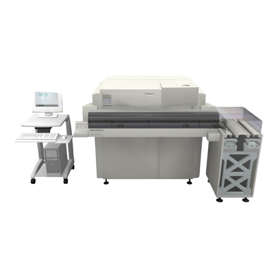
- Page 1 Service Manual i2000SR interface module i 2 0 0 0 S R I M Service Manual for the i2000SR Interface Module Document name: 625798100.APS.5.doc Last revised(ISO 8601): 2007-10-31 625798100.APS.5.doc Page 1 of 212...
-
Page 2: Table Of Contents
On-Line Carriers......................15 Diverters Description....................17 IM Antenna and Optical Sensors................19 i2000SR Instrument Indicator Light (IM pole lamps) functioning .. 20 RED LAMP ON: Error or Initializing................20 RED LAMP Blinking: SCC CLI communication error........... 20 YELLOW LAMP Blinking: .................... 20 GREEN LAMP ON: Running, Paused or Pausing ............ - Page 3 Modify Instrument Queue for instrument following i2000SR ........76 Modify Instrument Setup.INI file................77 Exercise i2000SR IM ....................78 Verify carriers movement from the APS Track to i2000SR IM ........80 Complete installation of i2000SR LAS ...............82 Retrofit of the I/O module pneumatic panel and circuit ....83 IOM Pneumatic Panel Differences ..........
-
Page 4: Overview
Service Manual O v e r v i e w Identification Data Module name: i2000SR Interface Module (i2000SR IM) Group Drawing no.: 625.100.00X Pneumatic layout: 625.107.00X Electrical layout: 625.800.00X Warnings Concerning Safety WARNING: Potential Biohazard Identifies an activity or area where potentially infectious material may be present. -
Page 5: Laser Safety
If any of the labels become damaged and/or illegible, replace them. LAB0033 is an illustration of the label recommended by Abbott Safety to be placed on the i2000SR and i2000SR IM closeout cover. DANGER: Class 2 Laser Radiation when open. Do not stare into beam. - Page 6 Service Manual DANGER: Laser Hazard Field Service Engineer (FSE) may be exposed to direct laser emissions in the i2000SR IM area with the i2000SR cover shields removed; be careful when performing diagnostics and maintenance operations with i2000SR cover shields removed.
-
Page 7: Description
An explanation of the principles of operation is also provided. i2000SR Interface Module The purpose of the i2000SR Interface Module (IM) is to transport samples to the ARCHITECT i2000SR instrument as a standalone unit or interfaced with an Automated Processing System (APS). As... - Page 8 Service Manual NOTE: Although the i2000SR IM can process samples independent of the APS, the IM cannot be installed independent of the APS. controlled microcontrollers. microcontrollers are interfaced to the APS via the CAN bus and are similar to the Tag Reader boards used to manage the functions of the track.
-
Page 9: Tube Lanes
Service Manual i2000SR interface module Tube Lanes The i2000SR IM consist of four transport belts that are used to create four tube lanes, each one dedicated to a specific task of moving APS Workcell on-line and i2000SR IM specific off-line carriers (See Figure 2 –... -
Page 10: Input And Output Areas
Entry Gate Queue (queue of 8 on-line carriers) Path of the APS Carriers Figure 3 – Carriers paths The following is the path of the Carriers routed to the i2000SR IM from the APS track Carriers with sample for the i2000SR are diverted from the main track to the i2000SR IM Entry Queue. -
Page 11: Path Of The I2000Sr Im Carriers
Service Manual i2000SR interface module Path of the i2000SR IM Carriers The following is the path of the i2000SR IM carriers processed on the IM. During initialization, carriers are organized into two queues (Routine and Priority) along Lane 3. As soon as a sample tube is placed into the first carrier of either the Priority or Routine position, it is routed from Lane 3 to Lane 2. -
Page 12: Process Controls
Service Manual During the APS operational mode, Workcell carriers identified as On-line Carriers can be processed along with the Off-line carriers. As the IM Off-line and Workcell On-line carriers have different RFID tags the IM routes all Off-line carriers to Lane 4 and the On-line carriers back to the Workcell, after processing. -
Page 13: Brief Description Of The Stop Gate Devices
EV1. This Type 3 gate operates when the carrier moving along the APS main track is either diverted into the i2000SR IM or continues along the APS track. If the carrier is diverted, Gate 0 and the standard track diverter (D0) activate to route the carrier to the IM. - Page 14 Gate 2 – is a set of three (Barcode) BCR Type 3 gate devices (G2 a, b, and c) located on the i2000SR IM Lane 1. The set stops and reads the carrier RFID tag and rotates the carrier to allow the Barcode reader to scan and identify the label on the tube.
-
Page 15: Off-Line Carriers
Service Manual i2000SR interface module a collision with a carrier arriving from Lane 3. Lane 3 carriers always have precedence over those traveling on Lane 2. At this stop gate, a Tag Reader identifies the carrier and the IM determines which of the following three scenarios is appropriate:... - Page 16 Service Manual into an empty carrier at this time. When the LED is green, tubes can be manually loaded into the carrier located at this gate. Gate 7a – (G7a) is on Lane 2 and is operated by electro valve EV10.
-
Page 17: Diverters Description
The IM has five Diverter Gates named D0, D1, D2a, D2b and D3. The diverters D1, D2a, D2b and D3 are unique to i2000SR IM and have a different design than those used on the main track. They are driven by the F/W and used to control the routing carriers to the final destination. - Page 18 Service Manual Diverter Control Description Reference Lane 3/2 EV15 Diverter D2b – Lane 3/1 Diverter – is located in the area of the gate G8 and the large disk. It is controlled by EV4 and is activated to route carriers from Lane 3 to Lane 1 via the opening created by D2a.
-
Page 19: Im Antenna And Optical Sensors
Diverter IM Antenna and Optical Sensors The i2000SR IM uses RFID Antenna and optical sensors to detect the presence of a carrier and/or sample tube. These devices are controlled by the F/W in the Master/Slave board located in the IM electrical box. -
Page 20: I2000Sr Instrument Indicator Light (Im Pole Lamps) Functioning
While in Standalone mode, a blinking yellow lamp is used to inform the operator of a sample presentation error. To prevent erroneous results, the IM via the CLI port will issue the i2000SR analyzer a Stop command. Page 20 of 212... -
Page 21: Green Lamp On: Running, Paused Or Pausing
CLI port to prevent the i2000SR analyzer from processing samples GREEN LAMP ON: Running, Paused or Pausing The green lamp is illuminated to indicate that the i2000SR and IM are operating without error and the communication link between i2000SR and IM is established. - Page 22 APS mode – IM Exercise mode cannot be performed while in APS mode. The APS Track Exercise will not pass carriers to the i2000SR IM. A detailed description of the movement of carriers while in i2000SR IM exercise mode exercise mode is contained in the description section. Stop: Standalone –...
-
Page 23: I2000Sr Im Pneumatics Components
Service Manual i2000SR interface module i2000SR IM Pneumatics Components Figure 8 – i2000SR IM pneumatic panel Description Gate Port EV Description GatePort Instrument i2000SR Gate 11 Exit Gate Instrument i2000SR Divert Gate Divert to Track Output Gate – release off-line... - Page 24 Service Manual Figure 9 – i2000SR IM pneumatic layout Page 24 of 212 625798100.APS.5.doc...
-
Page 25: I2000Sr Im Electrical Components
Service Manual i2000SR interface module i2000SR IM Electrical Components Figure 10 – i2000SR IM electrical block diagram 625798100.APS.5.doc Page 25 of 212... -
Page 26: Master Can Board Description
Service Manual MASTER CAN Board Description Table 1 – Master CAN Board Outputs Function Device Electro Port Antenna Control Description Valve Command Out – 1 STAT STAT - Activates the gate at Pipettor the STAT Pipettor Pass... - Page 27 Service Manual i2000SR interface module Table 2 – Master CAN Board Inputs Function Devic Electro Port Antenna Control Description Valve Command In – 1 Carrier Diag – Bit 0 A carrier detected as Presence it has exited the large 1 = ON...
-
Page 28: Master Can Board Segment Indicator
Service Manual MASTER CAN Board Segment Indicator LED Indicator Carrier at G3 Carrier at G4 STAT Probe Sample Probe SLAVE 0 CAN Board Description Table 3 – Slave 0 CAN Board Inputs - Outputs Function Device Electr... -
Page 29: Slave 0 Can Board Segment Indicator
Service Manual i2000SR interface module SLAVE 0 CAN Board Segment Indicator Carrier at G0 Carrier at Carrier at G1 Indicator SLAVE 1 CAN Board Description Table 4 – Slave 1 CAN Board Inputs Function Device Electro Port Antenna Control Description... - Page 30 Service Manual Table 5 – Slave 1 CAN Board Outputs Function Device Electro Port Antenna Control Description Valve Devices Out – 1 EV14 Routine Controls the carriers at the Input – Routine sample input. Pass/Pit A carrier with a Routine sample...
-
Page 31: Slave 1 Can Board Segment Indicator
Service Manual i2000SR interface module SLAVE 1 CAN Board Segment Indicator Carrier at Carrier at Carrier at Carrier at Indicator 625798100.APS.5.doc Page 31 of 212... -
Page 32: Electrical Panel Connectors
Track module antennas A0 and A1 A2 to A8 i2000SR IM antennas from A2 to A8 i2000SR IM three Motors (Lane 1 & 2 motor, Lane 3 & 4 motor, and Disk motor) Instrument Indicator light (IM Status pole lamps) - Page 33 A5, A6, A7 and A8 antennas are connected to SLAVE 1 CAN-BUS board. Figure 12 – i2000SR IM electrical box Description Main switch – Circuit breaker for power supply Power supply +24/5 V DC (Note: 5 VDC is not used.)
-
Page 34: I2000Sr Im Electrical Box Startup
IM Electrical Box startup Figure 13 – i2000SR IM main switch Figure 14 – i2000SR Keypad Description RUN button PAUSE button with pause LED STOP button i2000SR IM can be started in Standalone Mode or in APS Mode. Page 34 of 212 625798100.APS.5.doc... -
Page 35: Starting I2000Sr Im In Aps Mode
During ACCELERATOR APS logo screen, the LEDs on the Power Distribution will illuminate and the IOM pneumatic air valve will open. As i2000SR IM air supply is routed from the IOM pneumatic panel manifold, its air supply is not routed through the air valve. -
Page 36: Starting I2000Sr Im In Standalone Mode
• When the switch is in “i2000SR” position, the +24 VDC power supply in the i2000SR IM Electrical Box is used to supply the IM devices. The IM +24 VDC power supply is supplied by external AC power via J4. When the cable connected to J4 is connected to an AC power source, the +24 VDC power supply remains ON. -
Page 37: I2000Sr Im Track Initialization
). During IM initialization the following occurs: The IM Master Tag Reader Com port 1 establishes communication with the i2000SR via the SCC LAS port. If the communication is established, the LAS icon will be displayed on the i2000SR SCC snapshot screen. -
Page 38: Rebuilding Queues
Service Manual The IM module verifies the communication with the i2000SR analyzer via Master tag reader board port 1 and the green lamp on the lamp pole will be turned ON. When both the Priority and Routine Input Gate Status LEDs are green and the IM pole lamp is green, the system is ready to accept local tubes. - Page 39 Service Manual i2000SR interface module The following is a description of the carrier movement until the exercise is stopped: Carriers are in their initial queues. Lane 3 – Priority (G8) releases a carrier to Lane 4 (G6) Lane 3 – Routine (G7b) releases a carrier to Lane 2 (G5) Lane 3 –...
-
Page 40: Instructions For Assembly
IM Parts Shipped The i2000SR IM is shipped in one dedicated closed crate and labeled as LN 07L32-01 (IBL0045). The pallet contains all the components needed to install i2000SR Interface Module on a Workcell with a properly configured track interface. -
Page 41: Parts Shipped For A New Installation
Do not mix these pallets with the Workcell pallet. Figure 15 – i2000SR IM Off-Line Carrier NOTE: The i2000SR IM comes with its own set of 21 carriers. These carriers have the top plane painted gray to distinguish them from track carriers. -
Page 42: Assembly Procedure
Window Closeout with Process module LUI Keypad − Right and Left side covers • Reference the provided Workcell layout schematic, at the TMA to determine the location that the i2000SR IM is to be installed. Installation of the Instrument Indicator Light (pole lamps) •... -
Page 43: Installation Of The I2000Sr Im
Electrical box Installation of the i2000SR IM CAUTION: Lifting Hazard The installation of the i2000SR IM to the TMA module requires two service personnel: one person to hold the i2000SR IM module and the other to fasten bolts. The i2000SR IM gross weight is 18 kg (40 lbs). - Page 44 Figure 17 – Right orientation of the optical sensor cable Description Optical sensor body (on the main track) Diverter lever (after i2000SR IM installation) Optical sensor cable Figure 18 – Disk protection Description Disk upper protection...
- Page 45 Metal Screws. For Seismic protection, these metal screws are replaced with plastic screws Square Spring Nuts i2000SR IM Large Autotex disk Figure 20 - i2000SR IM pneumatic multi connectors Description Pneumatic multi connectors Pneumatic multi connectors fixing screws 625798100.APS.5.doc Page 45 of 212...
- Page 46 • While holding the IM in position, use the five (5) metal screws to fasten the i2000SR IM to the TMA. DO NOT tighten the screws. Figure 21 – i2000SR IM...
- Page 47 Using the track opening [1] as a reference, move the IM extrusion left and right as required to align its extreme edges [2 Figure 23) and 3] to the track opening [1] (See Figure 22 – i2000SR IM first alignment Figure 23 • Refer to Note that the Disk upper protection [1] is in alignment with the guide between tracks 1 and 2 [2].
- Page 48 Figure 23 – i2000SR IM first alignment • To assemble the i2000SR IM, use the metal screws fixed to the interface module. Once the analyzer and spur are positioned in a conclusive way, all metallic screws must be replaced with plastic screws.
-
Page 49: Pneumatic Connections
• If the installation is an upgrade, mount the pneumatic panel in a position in front of the i2000SR IM. In this manner, when the valve solenoid is manually pressed, the valve action can be observed. Figure 26 – Multi connectors and pneumatic panel 625798100.APS.5.doc... -
Page 50: Initial I2000Sr Support Procedure
IM during the procedure. • Remove the metal screws used to secure the i2000SR IM to the workcell and replace them with the plastic screws supplied. These plastic screws are required to ensure that in the event of seismic activity (earthquake), the analyzer will not cause damage to the workcell. - Page 51 IM assembly cut-out i2000SR bracket attachment • At the i2000SR LAS support bracket, adjust the two knurled knobs [1] in a manner that applies support to the i2000SR Figure 29 IM. (See Figure 29 – i2000SR Support Bracket 625798100.APS.5.doc...
- Page 52 Service Manual NOTE: As the support bracket is adjusted, ensure that the support feet [2] are aligned with the extrusion and are not in Figure 29 contact with the belts. (See Page 52 of 212 625798100.APS.5.doc...
-
Page 53: Electrical Connections
Antennae, power, and control connectors • If the installation of the i2000SR is a retrofit, install the electrical box on the TMA in a location that the TAG Reader LEDs can be observed as carriers are placed on an antenna. -
Page 54: Im Track Interface Cable Connections
Tube and Carrier (SICK) sensors Future CAN-BUS development cable IM Electrical Box Cable Connections Description Antennas connectors on electrical box Workcell CAN-BUS 24 V DC AUX power Barcode Reader cable i2000SR UPS 230 V AC main power Page 54 of 212 625798100.APS.5.doc... - Page 55 CLI Interface - (Master tag reader RS-233 port 2) to cable 625810280 to i2000SR SCC Edgeport port 1 (Com 3) +24 volt return wire extended from the i2000SR IM via a hole at J19. Routed to interface with a process path ground wire installed on the i2000SR IM (i2000SR Ground Wire) 625798100.APS.5.doc...
-
Page 56: I2000Sr Ground Wire Installation
Figure 33 – The 0.8 m 18 AWG wire • At the underside of the i2000SR IM locate the opening in the i2000 SR front panel used to route the STAT LLS cables and insert the screw terminal end of the wire. -
Page 57: Ac Power Connections
At the underside of the i2000SR IM support bracket, route the wire in a manner that it does not come in contact with the belt. • Connect the end of the wire to the J19 i2000SR LLS ground wire. AC Power connections •... -
Page 58: I2000Sr Im Lui Panel Installation Procedure
Service Manual i2000SR IM LUI Panel Installation Procedure • At the left end of the i2000SR IM, use two screws [1] (P/N 100474-001) M5X0.8, 20MM to mount the 202992 SPUR CAP Figure 36 PLATE [2]. Refer to Figure 36 –... - Page 59 Service Manual i2000SR interface module Figure 38 – 3 Button LUI Keypad • Connect the LUI Panel Cable to the keypad. • Slip the 3 Button LUI Housing (P/N 202997) [2] over the LUI bracket. Use two 190-32 screws (P/N 14494-306) [1] to secure Figure 40 the cover.
-
Page 60: I2000Sr / I2000Sr Im Alignment Procedure
Refer to • The difference between the left ends of the i2000SR and Figure 44 i2000SR IM is 145 +/- 3 mm (5.75 +/- 0.125”). Refer to • The support bracket alignment tabs are flush against the Figure 42 IM rear surface. - Page 61 For this procedure, refer to Architect i2000SR service documentation. • Adjust the i2000SR feet and support bracket knurled knobs, as required, to position the i2000SR to meet the following conditions: Action Reference Figure 42 – Support Bracket Reference Tabs...
- Page 62 [2]. Figure 44 - Differences between left ends of i200SR and IM The difference between the left end of the i2000SR IM and i2000SR frame [1] is 145 mm +/- 3 mm (5.75” +/- 0.125”) Page 62 of 212 625798100.APS.5.doc...
- Page 63 Service Manual i2000SR interface module Action Reference Figure 45 – Level i2000SR IM with track The i2000SR IM track is level with the track on the Workcell. Place a TM Carrier Leveling Aid (P/N 403.600.150 (202182) into the APS main track and a second aid on the i2000SR IM track.
- Page 64 Service Manual Action Reference Figure 48 – Level i2000SR Left/Right Place a level across the top of the i2000SR Sample and STAT pipettor to indicate left to right level of the i2000SR. Adjust the feet as required until the i2000SR is level.
-
Page 65: I2000Sr Im Horizontal Positioning Check
Service Manual i2000SR interface module i2000SR IM Horizontal Positioning Check REMARK This check should be executed only after i2000SR IM Figure 46 leveling (See It is important to verify that the gap between the 1st lane belt and the profile of the main track is between 0.5 & 1.0 mm. If the gap is too small, there may be interference between lane 1 belt and main track profile. -
Page 66: I2000Sr Im Vertical Positioning Check
Ensure that the profiles of the i2000 IM and Main Track remain square. Tighten the four screws. i2000SR IM Vertical Positioning Check REMARK This check should be executed only after i2000SR IM Figure 46 leveling (See It is important to verify that the upper surface of the 1 lane belt and the upper surface of the main track secondary track belt are at the same level in the ±... - Page 67 Figure 54 – Multi connector removing Figure 55 – Idler pulley adjusting At the end of the adjusting procedure, it is required to check the clearance between the i2000SR IM first lane belt and the main track secondary lane. To do this: •...
-
Page 68: Alignment Of Routine And Stat Sampling Probes, Gates And Antennae
Figure 59 The Gap Filler and its flange must match with the i2000SR cover. The flange is assembled to the Main Track cover by means of two screws inserted in two horizontal slots. Those slots permit horizontal adjustment. - Page 69 Service Manual i2000SR interface module Figure 57 – Track cover assembly Figure 58 – Flange assembly Figure 59 – Gap filler assembly 625798100.APS.5.doc Page 69 of 212...
-
Page 70: Install 7L46-01 Off-Line Carriers
Install 7L46-01 Off-line carriers • At the Routine Input gate (G7b), insert the 21 (P/N 7L46- 01) i2000SR IM off-line carriers. Ensure only carriers with a gray ring are installed. Figure 61 – i2000SR IM Carriers Page 70 of 212... -
Page 71: Initialize I2000Sr Im
Master Slave Port 2 (CLI) SCC LAS Edgeport port 4 (com 6) Master Slave Port 1 (LAS) NOTE: The i2000SR IM will not initialize unless the cable check is passed. • After the Snapshot screen on the System Control Center is displayed, press the green Run button on the keyboard. - Page 72 − Remove obstacle − Adjust carrier guides • The i2000SR support bracket feet must not come in contact with a belt, cable, or tube. • Check the tension of belts 1, 2, 3 and 4. V erification of belt tensioning Refer to the procedure.
-
Page 73: Verify Config Wizard I2000Sr Setting
05X is the CAN bus address of the Master Tag Reader in the IM electronic box. The Tag Reader board has two RS-232 communication ports. :1 is used to indicate that the i2000SR LAS communication is connected to port 1. Port 2 is not used for LAS communication. i2000SR... - Page 74 Service Manual b. CAN Boards NOTE: The i2000SR IM Master Tag Reader board in the Electronic Box(s) is not listed. Only Track CAN bus boards are listed. For each Track CAN bus boards Address Parameter: • A indicates the antenna connected to CN12 of the Tag Reader board.
- Page 75 Typically the next module is the Recapper. Select the Recapper Diverter Gate ALTERNATIVE NEXT QUEUE Not Connected QUEUE LENGTH NOTE: After the i2000SR IM Gate Queues lengths are changed, the change will not take affect until the i2000SR IM power has been cycled. 625798100.APS.5.doc Page 75 of 212...
-
Page 76: Modify Instrument Queue For Instrument Following I2000Sr
Should there be multiple i2000SR systems, change the instrument queue length of each following instrument that is not an i2000SR. Refer to the reference illustration. Note that as there is separation between the i2000SRs, the instrument queue for #3 is also set at... -
Page 77: Modify Instrument Setup.ini File
After the i2000SR IM Gate Queues lengths are changed, the change will not take affect Instrument Display Name = c16000 until the i2000SR IM power has been cycled Instrument Family = Clinical Chemistry Instrument Type Code = c16000 Buffer Overload Count = 30... -
Page 78: Exercise I2000Sr Im
Reload all INI files Exercise i2000SR IM GOAL: Use the i2000SR IM Track Exercise feature to check that IM devices move off-line carriers properly within the lanes. This exercise routine should be allowed to run continuously for a minimum of 3 hours. During the exercise, verify that all carriers and devices move properly. - Page 79 Service Manual i2000SR interface module NOTE: The i2000SR IM will not initialize unless the cable check is passed. • After the Snapshot screen on the System Control Center is displayed, press the green Run button on the keyboard. NOTE: If communication check fails (Blinking Red Lamp) and RUN button is pressed, all Off-line carriers are routed to lane 4.
-
Page 80: Verify Carriers Movement From The Aps Track To I2000Sr Im
Carriers must move properly from the track to the i2000SR IM. To verify, the diverter D0 state is changed to route all carriers from the main APS track into the i2000SR IM. As the on-line carriers arrive at IM entry queue, gate G1 will divert them to the IM. - Page 81 SCC LAS Edgeport port 1 (com 6) • Master Slave Port 1 (LAS) NOTE: The i2000SR IM will not initialize unless the cable check is passed. • After the pole lamp turns red and begins blinking, turn on the System Control Center for the i2000SR analyzer.
-
Page 82: Complete Installation Of I2000Sr Las
Continue APS track exercise until all carriers have been cycled through the IM at least once. • At the i2000SR IM Pneumatic Panel, reverse the tubing connections for Diverter DO EV2. This will restore normal diverter operation. Complete installation of i2000SR LAS... -
Page 83: Retrofit Of The I/O Module Pneumatic Panel And Circuit
Retrofit of the I/O module pneumatic panel and circuit To support the i2000SR, the pneumatic panel at the IOM must continuously supply air to the i2000SR IM when the APS workcell is shutdown and power is OFF. To provide this source of air, the IOM pneumatic panel has a manifold with a bank of manual valves. - Page 84 Using the 6 mm diameter tubing SMC TUPU0604 (P/N PNT0003) supplied; make a connection from the IOM pneumatic Figure 69 panel [7] to the i2000SR IM pneumatic panel [A] (See NOTE: The Festo Sensor is no longer being used to monitor the movement of the Z-Axis.
- Page 85 Service Manual i2000SR interface module of the i2000SR IM, ensure that there is an additional length of air supply tubing. Figure 70 – Pneumatic Panel Bypass At the IOM, open the Festo rear cover. Sensor At the left end, Tubing...
-
Page 86: Iom Pneumatic Panel Differences
To the I/O Module Robot To the Track Module To provide the i2000SR IM with an air source that is independent of the IOM air valve, a manifold has been added. After the site air is filtered [E], regulated [F] and stored in the TMA tank [L], the air is routed to a manifold [R] with manual distribution valves [P &... - Page 87 Output 8 mm diameter pipe to the tank Input 8 mm diameter pipe from the tank Output 6mm diameter pipe to the i2000SR IMs and free To the I/O Module 6 mm diameter pipe To the Track Module 6 mm diameter pipe 625798100.APS.5.doc...
-
Page 88: Replacement Procedures
This chapter describes the procedures to execute the removal and replacement operations required to keep the Workcell in efficient working condition and to verify it is operating correctly. Replacement of i2000SR IM REPLACEMENT PROCEDURE SCHEDULE no. 1 i2000SR IM replacement... - Page 89 Refer to the “Accelerator APS Operations Manual – the Workcell SECTION 5 – Operating Instructions” to execute the “Controlled power shutdown” of the Workcell. Disconnect the Workcell and i2000SR IM from the AC power source. Label the power connection to indicate that service is in progress and power must remain disconnected.
- Page 90 Service Manual STEPS REFERENCES Use a 14494-306 190-32 screw to attach the End Cap to the window closeout. Remove the screw in the Center Rail Remove the Hinge Mount (P/N 203621) and two front covers by removing the four (4) countersink screws [1].
- Page 91 Electrical box fasten points Pneumatic panel fasten bolts i2000SR IM body 12 At each of the four (4) i2000SR feet, mark the position on the floor and measure the distance between the bottom of the frame and the floor. 625798100.APS.5.doc...
- Page 92 13 Adjust the feet as required to lower the i2000SR and move the module away from the IM. As the i2000SR IM is no longer being supported, a second person is required to hold and support the IM. 14 Loosen the i2000SR bracket attachment screw to release the i2000SR IM from i2000SR.
- Page 93 [1]. Description Disk upper protection TMA assembly 18 Remove the new i2000SR IM group from the shipping platform and remove the packaging protection covers. Mount the disk’s metallic top protection and fasten it on the TMA.
- Page 94 Service Manual STEPS REFERENCES 20 Locate on the i2000SR IM the five plastic mounting bolts NOTE: As the i2000SR IM is mounted to the TMA, use care to prevent damage to the large Autotex disk. Fasten each bolt to fix the i2000SR...
- Page 95 24 Using the floor reference marks, reposition the i2000SR and adjust each foot to set the proper height 25 Place two TM Carrier Leveling Aids (P/N 403.600.150 (202182)) in a belt track.
- Page 96 Service Manual STEPS REFERENCES 27 Verify that the two carriers at the stop gate are under the vertical of the i2000SR sample points. Alignment of routine and If not, see STAT sampling gates procedure. Description Screw to loosen for stop...
- Page 97 Use care to ensure that all cables and tubing are not pinched, crimped or damaged. 31 At the front of the i2000SR IM, install the six (6) 100474-001 screws to mount the 203624 Window Support [1] and 203718 Bracket Lower Closeout.
- Page 98 Service Manual STEPS REFERENCES 32 Install the center cover by tightening the four (4) ¼ turn screws. 33 Install the screw in the Center Rail [2] Install the Hinge Mount (P/N 203621) and two front covers by installing the four (4) countersink screws [1].
- Page 99 Service Manual i2000SR interface module VERIFICATION STEPS REFERENCES With the i2000SR IM in the APS Refer to the “Accelerator APS Operations Manual – position, restore power to the SECTION 5 – Operating Instructions” to execute workcell. the “Restoring Power after a Controlled Shutdown”...
-
Page 100: Replacement Of I2000Sr Im Belts
Service Manual Replacement of i2000SR IM belts REPLACEMENT PROCEDURE SCHEDULE no. 2 i2000SR IM belts replacement Operation: Working area: i2000SR IM Mechanical Group: 625.102.00X PFD0304 (belt #1) PFD0302 (belt #2) Electrical Group: 625.800.00X Part no. PFD0301 (belt #3) - Page 101 Refer to the “Accelerator APS Operations Manual – the Workcell SECTION 5 – Operating Instructions” to execute the “Controlled power shutdown” of the Workcell. Disconnect the Workcell and i2000SR IM from the AC power source. Label the power connection to indicate that service is in progress and power must remain disconnected.
- Page 102 STEPS REFERENCES Remove the center cover by loosening the four (4) ¼ turn screws. At the front of the i2000SR IM, remove the six (6) 100474-001 screws used to mount the 203624 Window Support [1] and 203718 Bracket Lower Closeout.
- Page 103 STEPS REFERENCES 11 Follow i2000SR Replacement procedure to disassemble the i2000SR Track. Put it on a suitable working table. 12 Remove the metal cover by loosening the two screws. 13 Refer to the figure for terminology used in this procedure.
- Page 104 Service Manual STEPS REFERENCES 14 Disconnect the three connectors of the orange cables shown in the figure and remove the cable supports from assembly. The gray and maroon wires will be not disconnected. Their length will control the distance that the two sections can be separated.
- Page 105 Service Manual i2000SR interface module STEPS REFERENCES 17 Refer to the figure for terminology used in this procedure. The correct belt tensioning order is: Belt 1 – 2 – 3 – 4 18 Belt 1 Replacement – PFD0304 Remove the pneumatic multi connector bracket to access the screws shown in the figure.
- Page 106 Service Manual STEPS REFERENCES 20 Remove the screws indicated in the figure to remove tension from the belt of Lane 1 and replace it. 21 Belt 1 Tensioning Install the new belt and use the screws shown in the figure to apply tension to the belt of Lane 1.
- Page 107 Service Manual i2000SR interface module STEPS REFERENCES 23 Loosen the screws shown in the figure to remove from the belt of Lane 2. Install the new belt and use the screws shown in the figure to apply tension to the belt of the Lane 2.
- Page 108 Service Manual STEPS REFERENCES 28 Belt 4 Replacement – PFD0303 Remove the two screws that fasten Lane 4/Track Diverter Group and remove it. 29 Loosen the screws shown in the figure to remove the tension from the Lane 4 belt and replace it.
- Page 109 Service Manual i2000SR interface module STEPS REFERENCES 31 Assemble the head cover. 32 Follow the replacement of the i2000SR IM procedure to assemble the i2000SR Track. 625798100.APS.5.doc Page 109 of 212...
- Page 110 Service Manual VERIFICATION STEPS REFERENCES With the i2000SR IM in the APS Refer to the “Accelerator APS Operations Manual – position, restore power to the SECTION 5 – Operating Instructions” to execute workcell. the “Restoring Power after a Controlled Shutdown”...
-
Page 111: Replacement Of Light Pole Lamp
Service Manual i2000SR interface module Replacement of Light Pole Lamp REPLACEMENT PROCEDURE SCHEDULE no. 3 Light Pole Lamp replacement Operation: Working area: i2000SR IM Mechanical Group: 625.102.00X Electrical Group: 625.800.00X Part no. MEL0010 Machine Status: Controlled shutdown and power disconnected... - Page 112 Refer to the “Operations Manual – SECTION 5 – the Workcell Operating Instructions” to execute the “Controlled power shutdown” of the Workcell. Disconnect the Workcell and i2000SR IM from the AC power source. Locate the pole lamp near the i2000SR IM.
- Page 113 PAUSE button is pressed. Verify that the YELLOW lamp comes Allow the carriers to complete one cycle. At the i2000SR, use the SCC to place the i2000SR in RUN. Verify that after the i2000SR is in RUN, the GREEN lamp is ON.
- Page 114 Service Manual VERIFICATION STEPS REFERENCES Restore power to the workcell. Refer to the “Accelerator APS Operations Manual – SECTION 5 – Operating Instructions” to execute the “Restoring Power after a Controlled Shutdown” of the Workcell. Observe the screen for error If no error message was displayed the procedure messages.
-
Page 115: Replacement Of Belts Motor
Service Manual i2000SR interface module Replacement of belts motor REPLACEMENT PROCEDURE SCHEDULE no. 4 Belts motor replacement Operation: Working area: i2000SR IM Mechanical Group: 625.102.00X Electrical Group: 625.800.00X Part no. 579.400.00X Machine Status: Controlled shutdown and power disconnected Skill Required:... - Page 116 Refer to the “Operations Manual – SECTION 5 – the Workcell Operating Instructions” to execute the “Controlled power shutdown” of the Workcell. Disconnect the Workcell and i2000SR IM from the AC power source. Remove the one (1) 14494-306 .190- 32 screw to remove the (202990 original color or 203794 gray) right end cap.
- Page 117 STEPS REFERENCES Remove the center cover by loosening the four (4) ¼ turn screws. At the front of the i2000SR IM, remove the six (6) 100474-001 screws used to mount the 203624 Window Support [1] and 203718 Bracket Lower Closeout.
- Page 118 Service Manual STEPS REFERENCES At the end of the track, locate the two belt drive motors. 10 Remove the two power wires from the motor connectors. Unscrew the two bolts that fasten the motor bracket to the driver group and remove the motor.
- Page 119 Service Manual i2000SR interface module VERIFICATION STEPS REFERENCES With the i2000SR IM in the APS Refer to the “Accelerator APS Operations Manual – position, restore power to the SECTION 5 – Operating Instructions” to execute workcell. the “Restoring Power after a Controlled Shutdown”...
-
Page 120: Replacement Of Motor Belt Group
Service Manual Replacement of motor belt group REPLACEMENT PROCEDURE SCHEDULE no. 5 Motor belt group replacement Operation: Working area: i2000SR IM Mechanical Group: 625.102.00X Electrical Group: 625.800.00X Part no. 579.570.00X Machine Status: Controlled shutdown and power disconnected... - Page 121 Refer to the “Operations Manual – SECTION 5 – the Workcell Operating Instructions” to execute the “Controlled power shutdown” of the Workcell. Disconnect the Workcell and i2000SR IM from the AC power source. Remove the one (1) 14494-306 .190- 32 screw to remove the (202990 original color or 203794 gray) right end cap.
- Page 122 STEPS REFERENCES Remove the center cover by loosening the four (4) ¼ turn screws. At the front of the i2000SR IM, remove the six (6) 100474-001 screws used to mount the 203624 Window Support [1] and 203718 Bracket Lower Closeout.
- Page 123 Service Manual i2000SR interface module STEPS REFERENCES Follow i2000SR Service Manual to remove the i2000SR IM bottom covers. 10 Loosen the two bolts that fasten the motor bracket to the driver group, allowing the motor pulley to ease off from the motor belt.
- Page 124 Service Manual STEPS REFERENCES 12 Raise the Lane 1 & 2 belts to replace Lane 1 & 2 motor belt group or raise Lane 3 & 4 belts to replace Lane 3 & 4 motor belt group.
- Page 125 Service Manual i2000SR interface module VERIFICATION STEPS REFERENCES With the i2000SR IM in the APS Refer to the “Accelerator APS Operations Manual – position, restore power to the SECTION 5 – Operating Instructions” to execute workcell. the “Restoring Power after a Controlled Shutdown”...
-
Page 126: Replacement Of Disk Motor
Service Manual Replacement of disk motor REPLACEMENT PROCEDURE SCHEDULE no. 6 Disk motor replacement Operation: Working area: i2000SR IM Mechanical Group: 625.102.00X Electrical Group: 625.800.00X Part no. 579.410.00X Machine Status: Controlled shutdown and power disconnected Skill Required:... - Page 127 Refer to the “Operations Manual – SECTION 5 – the Workcell Operating Instructions” to execute the “Controlled power shutdown” of the Workcell. Disconnect the Workcell and i2000SR IM from the AC power source. Remove the one (1) 14494-306 .190- 32 screw to remove the (202990 original color or 203794 gray) right end cap.
- Page 128 STEPS REFERENCES Remove the center cover by loosening the four (4) ¼ turn screws. At the front of the i2000SR IM, remove the six (6) 100474-001 screws used to mount the 203624 Window Support [1] and 203718 Bracket Lower Closeout.
- Page 129 Service Manual i2000SR interface module STEPS REFERENCES Locate the disk motor. 10 Remove the two screws to remove the disk top cover. 11 Remove the two screws to remove the disk holder and the disk. 625798100.APS.5.doc Page 129 of 212...
- Page 130 Use Loctite to secure the screws. VERIFICATION STEPS REFERENCES With the i2000SR IM in the APS Refer to the “Accelerator APS Operations Manual – position, restore power to the SECTION 5 – Operating Instructions” to execute workcell.
- Page 131 VERIFICATION STEPS REFERENCES Check the APS screen for error messages. Perform i2000SR IM Carrier If no error messages or abnormal carrier Movement Verification. movements were noted, the procedure has successfully completed. Verify that all Off-line and On-Line...
-
Page 132: Replacement Of Belts 1 & 2 Drive Group
Service Manual Replacement of belts 1 & 2 drive group REPLACEMENT PROCEDURE SCHEDULE no. 7 Belts 1 & 2 drive group replacement Operation: Working area: i2000SR IM Mechanical Group: 625.102.00X Electrical Group: 625.800.00X Part no. 579.420.00X Machine Status:... - Page 133 Refer to the “Operations Manual – SECTION 5 – the Workcell Operating Instructions” to execute the “Controlled power shutdown” of the Workcell. Disconnect the Workcell and i2000SR IM from the AC power source. Label the power connection to indicate that service is in progress and power must remain disconnected.
- Page 134 STEPS REFERENCES Remove the center cover by loosening the four (4) ¼ turn screws. At the front of the i2000SR IM, remove the six (6) 100474-001 screws used to mount the 203624 Window Support [1] and 203718 Bracket Lower Closeout.
- Page 135 Remove belts from lanes 1 & 2. 14 Remove the four screws shown in the figure to replace belt 1 & 2 drive group. 15 Use the i2000SR IM replacement procedure to assemble. 16 Refer to the Replacement of i2000SR...
- Page 136 Service Manual VERIFICATION STEPS REFERENCES With the i2000SR IM in the APS Refer to the “Accelerator APS Operations Manual – position, restore power to the SECTION 5 – Operating Instructions” to execute workcell. the “Restoring Power after a Controlled Shutdown”...
-
Page 137: Replacement Of Belts 1 & 2 Idler Pulleys Groups
Service Manual i2000SR interface module Replacement of belts 1 & 2 idler pulleys groups REPLACEMENT PROCEDURE SCHEDULE no. 8 Belts 1 & 2 idler pulleys groups Operation: replacement Working area: i2000SR IM Mechanical Group: 625.102.00X 579.440.00X Electrical Group: 625.800.00X Part no. - Page 138 At the Workcell I/O module Track locate and turn OFF the track air tank valve. Follow Replacement of i2000SR IM procedure to remove the i2000SR IM Track. Then move the assembly on a suitable working table. Follow i2000SR IM belts replacement procedure to separate the two spur sections.
- Page 139 2 idler pulley group. 12 Install a new assembly 13 Perform the steps above in reverse order to reassemble the i2000SR IM 14 Refer to the Replacement of i2000SR IM belts procedure to set belts tension.
- Page 140 Service Manual VERIFICATION STEPS REFERENCES With the i2000SR IM in the APS Refer to the “Accelerator APS Operations Manual – position, restore power to the SECTION 5 – Operating Instructions” to execute workcell. the “Restoring Power after a Controlled Shutdown”...
-
Page 141: Replacement Of Belts 3 & 4 Drive Group
Service Manual i2000SR interface module Replacement of belts 3 & 4 drive group REPLACEMENT PROCEDURE SCHEDULE no. 9 Belts 3 & 4 drive group replacement Operation: Working area: i2000SR IM Mechanical Group: 625.102.00X Electrical Group: 625.800.00X Part no. 579.430.00X Machine Status:... - Page 142 3 idler pulley group in the direction of the arrow. Remove belt from lane 3. Remove the three screws shown in the figure to remove the i2000SR IM power switch cover. Page 142 of 212 625798100.APS.5.doc...
- Page 143 Service Manual i2000SR interface module STEPS REFERENCES Loosen the two screws that fasten Lane 4/Track Diverter Group and remove it. 10 Loosen the two screws shown in the figure to move the belt 4 idler pulley group in the direction of the arrow.
- Page 144 Service Manual VERIFICATION STEPS REFERENCES With the i2000SR IM in the APS Refer to the “Operations Manual – SECTION 5 – position, restore power to the Operating Instructions” to execute the “Restoring workcell. Power after a Controlled Shutdown” of the Workcell.
-
Page 145: Replacement Of Belts 3 & 4 Idler Pulleys Groups
Service Manual i2000SR interface module Replacement of belts 3 & 4 idler pulleys groups REPLACEMENT PROCEDURE SCHEDULE no. 10 Belts 3 & 4 idler pulleys groups Operation: replacement Working area: i2000SR IM Mechanical Group: 625.102.00X 579.440.00X Electrical Group: 625.800.00X Part no. - Page 146 Refer to the “Operations Manual – SECTION 5 – the Workcell Operating Instructions” to execute the “Controlled power shutdown” of the Workcell. Disconnect the Workcell and i2000SR IM from the AC power source. Follow the belts 3 & 4 drive group...
- Page 147 11 Perform the steps above in reverse order to reassemble the i2000SR IM. 12 See the Replacement of i2000SR IM belts procedure to set the belts tension.
- Page 148 Service Manual VERIFICATION STEPS REFERENCES With the i2000SR IM in the APS Refer to the “Accelerator APS Operations Manual – position, restore power to the SECTION 5 – Operating Instructions” to execute workcell. the “Restoring Power after a Controlled Shutdown”...
-
Page 149: Replacement Of I2000Sr Im Antennas
Service Manual i2000SR interface module Replacement of i2000SR IM antennas REPLACEMENT PROCEDURE SCHEDULE no. 11 Antennas replacement Operation: Working area: i2000SR IM Mechanical Group: 625.102.00X Electrical Group: 625.800.00X Part no. 027.200.00X Machine Status: Controlled shutdown and power disconnected Skill Required:... - Page 150 Service Manual WARNING: Potential Biohazard. This is an activity or area where you may be exposed to potentially infectious material. Refer to “Section 4 - Hazards and Warnings” of the Accelerator Service Manual Reduce exposure by using proper personal protection equipment and cleaning surfaces with 0.1% sodium...
- Page 151 Refer to the “Operations Manual – SECTION 5 – the Workcell Operating Instructions” to execute the “Controlled power shutdown” of the Workcell. Disconnect the Workcell and i2000SR IM from the AC power source. Remove the one (1) 14494-306 .190- 32 screw, to remove the (202990 original color or 203794 gray) right end cap.
- Page 152 Service Manual STEPS REFERENCES Remove the center cover by loosening the four (4) ¼ turn screws. i2000SR IM antenna locations are shown in the figure. Track antenna Figure 6 locations are shown in The antenna can be accessed by raising the appropriate belt.
- Page 153 Service Manual i2000SR interface module VERIFICATION STEPS REFERENCES With the i2000SR IM in the APS Refer to the “Accelerator APS Operations Manual – position, restore power to the SECTION 5 – Operating Instructions” to execute workcell. the “Restoring Power after a Controlled Shutdown”...
-
Page 154: Replacement Of Belt Disk
Service Manual Replacement of belt disk REPLACEMENT PROCEDURE SCHEDULE no. 12 Belt disk replacement Operation: Working area: i2000SR IM Mechanical Group: 625.102.00X 625.102.18X Electrical Group: 625.800.00X Part no. 625.102.99X Machine Status: Controlled shutdown and power disconnected Skill Required:... - Page 155 Service Manual i2000SR interface module STEPS REFERENCES Perform the controlled shutdown of Refer to the “Operations Manual – SECTION 5 – the Workcell Operating Instructions” to execute the “Controlled power shutdown” of the Workcell. Remove the one (1) 14494-306 .190-...
- Page 156 STEPS REFERENCES Remove the center cover by loosening the four (4) ¼ turn screws. At the front of the i2000SR IM, remove the six (6) 100474-001 screws used to mount the 203624 Window Support [1] and 203718 Bracket Lower Closeout.
- Page 157 Remove the cap with a bladed tool. Unscrew the auto-locking screw. Remove spacer, spring and then the disk. Install a new disk. 10 Perform the steps above in reverse order to reassemble the i2000SR IM. 625798100.APS.5.doc Page 157 of 212...
- Page 158 Service Manual VERIFICATION STEPS REFERENCES With the i2000SR IM in the APS Refer to the “Accelerator APS Operations Manual – position, restore power to the SECTION 5 – Operating Instructions” to execute workcell. the “Restoring Power after a Controlled Shutdown”...
-
Page 159: Replacement Of The Big Belt Disk
Service Manual i2000SR interface module Replacement of the big belt disk REPLACEMENT PROCEDURE SCHEDULE no. 13 Big belt disk replacement Operation: Working area: i2000SR IM Mechanical Group: 625.102.00X Electrical Group: 625.800.00X Part no. 625.103.09X Machine Status: Controlled shutdown and power disconnected... - Page 160 Service Manual STEPS REFERENCES Perform the controlled shutdown of Refer to the “Operations Manual – SECTION 5 – the Workcell Operating Instructions” to execute the “Controlled power shutdown” of the Workcell. Remove the one (1) 14494-306 .190-...
- Page 161 Service Manual i2000SR interface module STEPS REFERENCES At the front of the i2000SR IM, remove the six (6) 100474-001 screws used to mount the 203624 Window Support [1] and 203718 Bracket Lower Closeout. Remove the two (2) screws used to secure the 203717 Lower Closeout to the Window Support.
- Page 162 Service Manual STEPS REFERENCES Remove the two screws to remove the disk holder and disk. 10 Install a new disk. 11 Perform the steps above in reverse order to reassemble the i2000SR IM. Page 162 of 212 625798100.APS.5.doc...
- Page 163 Service Manual i2000SR interface module VERIFICATION STEPS REFERENCES With the i2000SR IM in the APS Refer to the “Accelerator APS Operations Manual – position, restore power to the SECTION 5 – Operating Instructions” to execute workcell. the “Restoring Power after a Controlled Shutdown”...
-
Page 164: Replacement Of The Carrier Spinning Group
Service Manual Replacement of the Carrier Spinning Group REPLACEMENT PROCEDURE SCHEDULE no. 14 Carrier Spinning Group replacement Operation: Working area: i2000SR IM Mechanical Group: 625.102.00X Electrical Group: 625.800.00X Part no. 579.945.00X Machine Status: Controlled shutdown and power disconnected... - Page 165 Refer to the “Operations Manual – SECTION 5 – the Workcell Operating Instructions” to execute the “Controlled power shutdown” of the Workcell. Disconnect the Workcell and i2000SR IM from the AC power source. Label the power connection to indicate that service is in progress and power service must remain disconnected.
- Page 166 STEPS REFERENCES Remove the center cover by loosening the four (4) ¼ turn screws. At the front of the i2000SR IM, remove the six (6) 100474-001 screws used to mount the 203624 Window Support [1] and 203718 Bracket Lower Closeout.
- Page 167 3 mm Allen key. 14 Attach the barcode reader on the new carrier spinning group. 15 Assemble the new group on the i2000SR IM assembly. Do not fasten the two screws at this point. 625798100.APS.5.doc Page 167 of 212...
- Page 168 STEPS REFERENCES 16 Use the Spur Positioning tool (P/N 475.110.320 (204148)) to test the distance between the i2000SR assembly and the bottom side of the Pass Cylinder Head. 17 That thickness must be equal to 0.3 mm with +0.00 –0.02 mm of tolerance.
- Page 169 Service Manual i2000SR interface module VERIFICATION STEPS REFERENCES With the i2000SR IM in the APS Refer to the “Accelerator APS Operations Manual – position, restore power to the SECTION 5 – Operating Instructions” to execute workcell. the “Restoring Power after a Controlled Shutdown”...
-
Page 170: Auxiliary Procedures
Service Manual A u x i l i a r y P r o c e d u r e s This chapter describes the procedures to safely execute the alignment operations required performing service maintenance operations on the Workcell. - Page 171 CAUTION: Class 2 Laser Radiation when open. Do not stare into beam. Avoid eye exposure to laser light. STEPS REFERENCES Initialize the i2000SR IM in either the APS or Standalone modes. Remove the one (1) 14494-306 .190-32 screw, to remove the (202990 original color or 203794 gray) right end cap.
- Page 172 Service Manual STEPS REFERENCES Remove the screw in the Center Rail [2] Remove the Hinge Mount (P/N 203621) and two front covers by removing the four (4) countersink screws [1]. Remove the center cover by loosening the four (4) ¼ turn screws.
- Page 173 Service Manual i2000SR interface module STEPS REFERENCES Place a tube without a barcode label into a routine input carrier. When the carrier is routed to the barcode position, a red beam will be emitted. Move the body of the BCR around its axis to orient it.
- Page 174 Service Manual STEPS REFERENCES Within the Assistant application, select “Test a connected scanner” Then select “Next” At the resulting screen, select “Monitoring” Using the screen image graph and green indicator bar, adjust the position of the scanner in a manner that it yields consistently good reading.
- Page 175 Verify that the barcodes are correctly read and samples are processed. If i2000SR IM is in standalone mode, Requires a PC running BARCODE SICK SCANNER the BCR alignment can be checked CLV 422-0010 software and a standard serial null...
-
Page 176: Alignment Of Routine And Stat Sampling Gates
Service Manual Alignment of routine and STAT sampling gates ALIGNMENT PROCEDURE SCHEDULE no. 16 Routine and STAT Sampling gates Operation: alignment Working area: i2000SR IM Mechanical Group: 625.102.00X Electrical Group: 625.800.00X Part no. 515.405.00X Machine Status: Operating in standalone mode... - Page 177 REFERENCES Stop the i2000SR IM. Refer to the “Operations Manual – SECTION 5 – Operating Instructions” chapter to stop the i2000SR IM in standalone or Workcell controlled mode. Remove the screw in the Center Rail Remove the Hinge Mount (P/N...
- Page 178 Service Manual STEPS REFERENCES At the i2000SR SCC, perform Sample and STAT probe calibrations Maintenance, As Needed, the appropriate probe to calibrate. 1111 Sample Probe Calibration 1117 STAT Probe Calibration NOTE: At the following screen prompt; Use the (p/n 204021) LAS pipettor calibration tool illustrated in the reference area.
- Page 179 Loosen the gate positioning screw and move the gate left or right to search the right position. 10 At the i2000SR SCC, reposition the probe and gate as required to precisely center probe. When precisely centered, use SCC screen commands to save the probe position.
- Page 180 16 Follow the i2000SR screen menu options to lower the probe over the tool. 17 Verify that both the i2000SR Sample and STAT probes are aligned perpendicular to the tube (center of the tool). If the rear feet are too low, the probe will touch the back of the tool/tube [2].
- Page 181 Service Manual i2000SR interface module STEPS REFERENCES 18 At the i2000SR feet, use the nut to lock the feet. VERIFICATION STEPS REFERENCES Perform a control run on any routine and STAT assay. Verify that probe enters the sample tube in a manner that ensures that it does not come in contact with the side of the tube.
-
Page 182: Sample And Stat Antennae Alignment Verification Procedure
Service Manual Sample and STAT Antennae alignment verification procedure ALIGNMENT PROCEDURE SCHEDULE no. 17 Verification of the alignment of the Operation: Sample and STAT antennae Working area: i2000SR IM Mechanical Group: 625.102.00X 027.200.00X Electrical Group: 625.800.00X Part no. - Page 183 Service Manual i2000SR interface module WARNING: Potential Biohazard. This is an activity or area where you may be exposed to potentially infectious material. Refer to “Section 4 - Hazards and Warnings” of the Accelerator Service Manual Reduce exposure by using proper personal protection equipment and cleaning surfaces with 0.1% sodium...
- Page 184 STEPS REFERENCES Remove the center cover by loosening the four (4) ¼ turn screws. Open the front panel of the i2000SR IM electrical box and locate the MASTER, SLAVE 0, and SLAVE 1 CAN-BUS board 7-segments red displays. Switch on the i2000SR IM in standalone mode.
- Page 185 Service Manual i2000SR interface module STEPS REFERENCES Start a track i2000SR IM Track Exercise. Press the STOP button on the LUI Panel when at least two carriers have been released and routed to belt #1 (Sample (A4) and STAT (A3) pipettor...
- Page 186 Service Manual STEPS REFERENCES If it is impossible to read any number Antenna Displayed value on the proper display, check for MASTER Board antenna cable connections or replace antenna. If the number appears on a wrong display, or if the displayed number is wrong, the antenna connector is inverted with another.
-
Page 187: Antennas Test Procedure
Service Manual i2000SR interface module Antennas test procedure ALIGNMENT PROCEDURE SCHEDULE no. 18 Test of antennas proper functioning Operation: Working area: i2000SR IM Mechanical Group: 625.102.00X 027.200.00X Electrical Group: 625.800.00X Part no. 027.100.00X Machine Status: Operating in standalone mode Skill Required:... - Page 188 CAUTION: Class 2 Laser Radiation when open. Do not stare into beam. Avoid eye exposure to laser light. STEPS REFERENCES Open the front panel of the i2000SR IM electrical box and locate the MASTER, SLAVE 0, and SLAVE 1 CAN- BUS board 7-segments red displays.
- Page 189 Service Manual i2000SR interface module STEPS REFERENCES Switch on the i2000SR IM in standalone mode. (Power switch in “i2000 SR” position). Wait until the green lamp on the light pole comes on. To access antennae located along belts 1 and 2, the front and center covers must be removed.
- Page 190 Service Manual STEPS REFERENCES Move an i2000SR IM carrier (not a Workcell carrier) near the antenna to be tested. Refer to the figure on the right for antenna location and numbering. Manually move the carrier along the...
-
Page 191: Verification Of Belt Tensioning
Service Manual i2000SR interface module Verification of belt tensioning ALIGNMENT PROCEDURE SCHEDULE no. 19 Belt tensioning verification Operation: Working area: i2000SR IM Mechanical Group: 625.102.00X PFD0304 PFD0302 Electrical Group: 625.800.00X Part no. PFD0301 PFD0303 Machine Status: Controlled shutdown and power disconnected... - Page 192 Disconnect all connectors that may be in the way to perform tensioning test. Using the belt tensioning tool (P/N 475.110.190 (203930-01)) verifies the belt tension. The i2000SR IM assembly must be placed horizontally during tensioning verification procedure. Page 192 of 212 625798100.APS.5.doc...
- Page 193 36 mm (1” 27/64) with a ± 6 mm (15/64”) of admissible tolerance. If belt tension adjustment is required, use the Replacement of i2000SR IM belts procedure to access the mounting screws. Restore all electrical connections. 10 Replace all covers.
-
Page 194: Verification Of Carrier Routing
Service Manual Verification of Carrier Routing Verification PROCEDURE SCHEDULE no. 20 i2000SR IM carrier routing verification Operation: Working area: i2000SR IM Mechanical Group: 625.102.00X Electrical Group: 625.800.00X Part no. - - - Machine Status: Controlled running Skill Required:... - Page 195 Service Manual i2000SR interface module STEPS REFERENCES Remove the one (1) 14494-306 .190- 32 screw, to remove the (202990 original color or 203794 gray) right end cap. NOTE: The front bottom edge is captured in the window trim between lanes 2 and...
- Page 196 If no error message was reported the procedure messages. has successfully completed. Perform i2000SR IM Track Exercise: At the i2000SR IM LUI keypad press and hold the RUN button as the PAUSE button is pressed. As carriers are moved, check the...
- Page 197 Ensure that no On-line carriers were routed to lane #4. At the APS, press PAUSE Allow all On-line carriers to leave the i2000SR and return to the main track Restore the D0 tubing connections at Stop Track Exercise. Select Diagnostics, Track, Track Exercise, Stop.
-
Page 198: Tag Reader Can Bus Board Firmware Installation
Tag Reader CAN BUS Board Firmware Operation: Installation This procedure is to be used to upgrade the firmware on the Tag Purpose: Reader CAN BUS Boards used on the workcell track and i2000SR electronic box i2000SR IM 625.102.00X Working area:... - Page 199 TagReaderHCi2000sr Slave XX.H86 Turn OFF the power supply to the Tag Reader CAN bus board At the i2000SR IM – turn the i2000SR/0/APS switch to the center OFF (0) position. Track Tag Reader CAN bus board – Disconnect power cable at CN1 [1].
- Page 200 Reader CAN bus board. Track Tag Reader CAN bus board – Connect power cable at CN1 [1]. i2000SR IM – turn the i2000SR/0/APS switch to the i2000SR position. 10 Verify that the power LED and the digital display are ON and a zero (0) is displayed.
- Page 201 Service Manual i2000SR interface module STEPS REFERENCES 12 If Remove All is displayed in the FLASH/OTP Memory Device window, press the Remove All button. 13 In the File window, press Select All. 14 In the File window, press Add Sel. >>...
- Page 202 Service Manual STEPS REFERENCES 17 After the board firmware is successfully loaded, press Disconnect. 18 At the Tag Reader Board, disconnect the serial cable. 19 Turn OFF the power to the Tag Reader CAN Bus board. 20 Set the Dip-Switches back to the original configuration.
-
Page 203: Preventive Maintenance Procedures
Service Manual i2000SR interface module P r e v e n t i v e M a i n t e n a n c e P r o c e d u r e s This chapter provides the various system schedules and as needed service maintenance procedures. - Page 204 Stop the i2000SR IM. Refer to the “Operations Manual – SECTION 5 – Operating Instructions” chapter to stop the i2000SR IM in standalone or Workcell controlled mode. To access the gears located at the ends of belts 1 and 2, the front and center covers must be removed.
- Page 205 Service Manual i2000SR interface module STEPS REFERENCES Remove the center cover by loosening the four (4) ¼ turn screws. Remove the 3 button LUI panel bracket [1] by removing the two screws [2] Disconnect LUI cable. 625798100.APS.5.doc Page 205 of 212...
- Page 206 Service Manual STEPS REFERENCES Remove the two screws [1] to remove the side panel [2]. Remove the metal cover by loosening the two screws. Verify that the gears group has an adequate amount of grease. If not, use a clean cloth and remove the old grease.
- Page 207 (Power switch in “i2000 SR” position). After initialization process, press and hold Pause and Run button on Keypad to start the i2000SR IM in exercise mode. Verify that belts/gears rotate without noise and there are no grease stains.
-
Page 208: Spare Parts List
S p a r e Pa r t s L i s t This chapter contains the list of the Workcell spare parts. The list includes all parts that the manufacturer foresees will be replaceable. i2000SR IM part list Group/Component Part Number Image... - Page 209 Service Manual i2000SR interface module Group/Component Part Number Image Note Pneumatic i2000SR IM pipes, electrical 625.107.00X Pneumatic Panel cables and 8-203846-0X Assembly connectors included. Electrical cables, boards, 625.840.00X i2000SR IM components Electrical box Assembly 8-203847-0X and connectors included. 579.400.00X i2000SR IM...
- Page 210 Service Manual Group/Component Part Number Image Note 579.420.00X i2000SR IM - - - Belt 1 & 2 Drive Group 8-203836-0X 579.430.00X i2000SR IM - - - Belt 3 & 4 Drive Group 8-203837-0X i2000SR IM 579.440.00X Suitable for Belt...
- Page 211 Service Manual i2000SR interface module Group/Component Part Number Image Note 579.480.00X i2000SR IM Configured with - - - Slave Tag Reader Board *.scl file 8-203832-0X 579.490.00X i2000SR IM - - - Lane 3/1 Diverter Group 8-203842-0X i2000SR IM 579.500.00X Lane 4/Track Diverter...
- Page 212 Service Manual Group/Component Part Number Image Note 625.102.99X i2000SR IM Small disk 8-204006-0X 625.103.09X i2000SR IM - - - Large Disk 8-203862-0X 027.200.00X i2000SR IM - - - Antenna 8-203863-0X Suitable for A0 625.810.18X i2000SR IM - - -...
Need help?
Do you have a question about the i2000SR and is the answer not in the manual?
Questions and answers