Table of Contents

Summary of Contents for Protec EVC40
- Page 1 EVC40 EMERGENCY VOICE COMMUNICATION SYSTEM COMMISSIONING MANUAL Protec Fire Detection PLC, Protec House, Churchill Way, Nelson, Lancashire, BB9 6RT. Telephone: +44 (0) 1282 717171 Fax: +44 (0) 1282 717273 Web: www.protec.co.uk Email: sales@protec.co.uk...
- Page 2 Author Date Document Creation J Lowcock 29/05/09 Remote Call Indicator and handset details included J Lowcock 02/09/09 Disable Toilet Alarm cable included J Lowcock 23/09/09 New features J Lowcock 22/12/10 93-346-80 Issue 4 © Copyright Protec Fire Detection PLC 2011...
-
Page 3: Table Of Contents
..........................32 UZZER ISABLED ) ..................32 UTSTATION AULT ANDSET AULT ..........................32 EVICE ISSING CCL C ...........................32 REAK CCL S .......................32 CREEN REAK OCL S ........................32 CREEN REAK OCL C ...........................32 REAK 93-346-80 Issue 4 © Copyright Protec Fire Detection PLC 2011... -
Page 4: Overview
40 devices connected per loop, these can either disabled refuge points, Disabled toilet alarms or fire telephones or a mix of all three Disabled Disabled Fire Refuge Point Toilet Alarm Telephone 93-346-80 Issue 4 © Copyright Protec Fire Detection PLC 2011... -
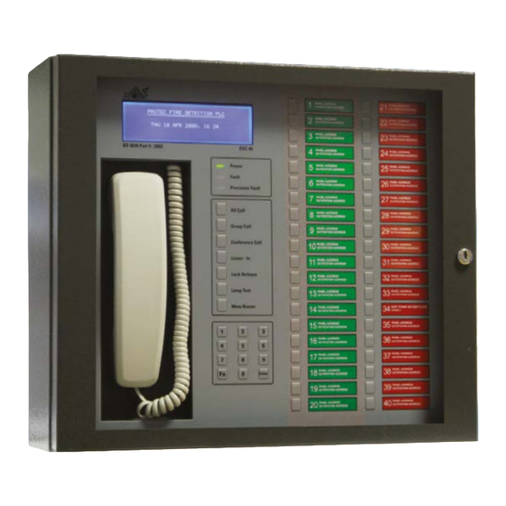
Page 5: Main Control Unit (Mcu)
Telephone handset used for all communications. Control and Mode Selection Switches Buttons used for mode selection and basic functions. Numeric Keypad Used for code entry and advanced user functions in conjunction with the LCD. 93-346-80 Issue 4 © Copyright Protec Fire Detection PLC 2011... -
Page 6: Operating The Evc
Select the Outstation to answer by pressing the relevant button. Flashing red indicators show other calls are waiting. Waiting calls do not produce the Ring Tone whilst a call is connected. 93-346-80 Issue 4 © Copyright Protec Fire Detection PLC 2011... - Page 7 NOTE – Factory Default software settings has buttons 33 – 36 allocated as panel handsets. Therefore button 33 is allocated as handset on panel 1 and flashes when the handset is lifted or called. As will 34 – 36 on their respective panels. 93-346-80 Issue 4 © Copyright Protec Fire Detection PLC 2011...
-
Page 8: Outstation Operation
Replacing the handset on a Fire Telephone Unit b) The MCU controller replacing their handset LED Colour Green Outstation Healthy Flashing Red Call waiting Steady Red Call acknowledge Steady Orange - Fault 93-346-80 Issue 4 © Copyright Protec Fire Detection PLC 2011... -
Page 9: Commissioning The Evc
At the control panel, check the cable resistance across each conductor is less than 15. At each outstation disconnect the ribbon cable from the test header and connect to the outstation. 93-346-80 Issue 4 © Copyright Protec Fire Detection PLC 2011... -
Page 10: Control Panel Setup
LCD displays either L3 (for a new device) or R3 (for a re-logged device). L1/2 or R1/2 means the outstation can only be seen from one side of the loop. 93-346-80 Issue 4 © Copyright Protec Fire Detection PLC 2011... - Page 11 X - at address 35 could also indicate a double address or the device has gone missing since the last log. 93-346-80 Issue 4 © Copyright Protec Fire Detection PLC 2011...
- Page 12 Display group allocation in hexadecimal format Display loop device type (0 = Disable Toilet, 1 = Simple Socket, 2 = Fire Telephone, 3 = Refuge Point) Enter Save the current changes. 93-346-80 Issue 4 © Copyright Protec Fire Detection PLC 2011...
-
Page 13: Log Pdps
This shows a system with 2 PDPs that have been logged before. Note that for PDPs the logging reports only L or R. 1 PDPS FOUND, NO CHANGE (01-10) PRESS ENTER: SAVE, 1: RE-LOG AND 0: EXIT 93-346-80 Issue 4 © Copyright Protec Fire Detection PLC 2011... -
Page 14: Log Control Loop
After a re-log the display will become: 2 PANELS FOUND, NO CHANGE (01-10) @ R3 - PRESS ENTER: SAVE, 1: RE-LOG AND 0: EXIT 93-346-80 Issue 4 © Copyright Protec Fire Detection PLC 2011... -
Page 15: Loop Balancing
REPLACE HANDSET Option 3 Control Loop In, follow on screen LCD instructions until a clear 1KHz tone can be heard. LIFT HANDSET ADJUST VR3 REPLACE HANDSET Exit menus. 93-346-80 Issue 4 © Copyright Protec Fire Detection PLC 2011... -
Page 16: Outstation Final Setup
Handset. If there is feedback the volume setting is too high, therefore, back off the volume slightly by adjusting VR5 and retest. Repeat this for all the remaining outstations. 93-346-80 Issue 4 © Copyright Protec Fire Detection PLC 2011... -
Page 17: Mcu, Rcu And Alp Units
MCU Power Up the panel. Connect both the mains and the battery supplies. Refer to Figure 3-1 a photograph of the EVC40 Processor Board: Figure 3-1 Processor Board The MCU/ALP Address Switch has two functions: The bottom 5 switches (1 to 5) are used to address the panel in binary, switch 1 is bit 1. - Page 18 Once the site file has been downloaded the outstations group data can take up to 40 minutes (1 minute per outstation) to update. To save time after downloading the site file re-log the loop. 93-346-80 Issue 4 © Copyright Protec Fire Detection PLC 2011...
-
Page 19: Commissioning An Alp
Complete a final outstation test by activation any outstation on the ALP loop and ensure the call can be accepted at the master panel. Ensure two way communication is established. 93-346-80 Issue 4 © Copyright Protec Fire Detection PLC 2011... -
Page 20: Scan Outstations And Missed Replies
- Pulse error, incorrect message length received back from the loop device - Checksum error - Command - Acknowledgement - Boundary Error, received incomplete data, generally occurs when outstations isolator close. 93-346-80 Issue 4 © Copyright Protec Fire Detection PLC 2011... - Page 21 The three columns at the right side of the LCD (0001) are counters, top counter for the outstation loops, middle counter for the control loop and the bottom counter for the PDP loop. 93-346-80 Issue 4 © Copyright Protec Fire Detection PLC 2011...
-
Page 22: Disabled Toilet Alarm
A fast bleep will be the audio indication of the toilet alarm being activated, this can be muted at the panel by pressing ‘Mute’. ALARM DISABLED TOILET ALARM: DISABLED TOILET ALARM LOCATION: SITE RELATED TEXT 1 ALARM TIME: TIME / DATE ENTER/FN: SCROLL 93-346-80 Issue 4 © Copyright Protec Fire Detection PLC 2011... -
Page 23: Connection Details For First City Toilet Alarm
5.2 Connection details for First City Toilet Alarm Protec recommending the use of twisted pair cable (eg screened or unscreened CAT5) between the disabled toilet alarm output and the outstation Outstation Back Disabled + Toilet Ceiling Pull Cord RRU Reset... -
Page 24: Connection Details For Hark Toilet Alarm
5.3 Connection details for Hark Toilet Alarm Protec recommending the use of twisted pair cable (eg screened or unscreened CAT5) between the disabled toilet alarm output and the outstation Note. Mains must be turned off or Power Supply incorporating disconnected before... -
Page 25: Fire Input
If the user requires continuous operation from the outstations then no connection to the fire input is required. PROTEC FIRE DETECTION PLC SYSTEM DISABLED 22 MAY 09:29 Disabled Toilet Alarms will still function while the system is disabled. 93-346-80 Issue 4 © Copyright Protec Fire Detection PLC 2011... -
Page 26: Terminal Board
7.0 Terminal Board LD14 LD13 LD11 LD16 LD15 LD12 LD10 93-346-80 Issue 4 © Copyright Protec Fire Detection PLC 2011... - Page 27 Drive outstation loop from both sides. Lit if driving from both ends LD16 Loop Fault. On when fault on outstation loop. either a full open circuit (not partial) or short circuit 93-346-80 Issue 4 © Copyright Protec Fire Detection PLC 2011...
-
Page 28: Remote Call Indication
The call indicator will operate when either an outstation or disabled toilet alarm is operated. Connection of the remote indicator is as follows; Terminal Board 93-346-80 Issue 4 © Copyright Protec Fire Detection PLC 2011... -
Page 29: Call Features
1 to 8. Select the require group and press enter to enable the call to the required group. CALL GROUP ALL CALL ALL CALL: GROUP 2 GROUP: 2 LOCATION: SITE RELATED TEXT 1 CALL TIME: TIME / DATE ENTER/FN: SCROLL 93-346-80 Issue 4 © Copyright Protec Fire Detection PLC 2011... -
Page 30: Conference Call
TIME: TIME / DATE ENTER/FN: SCROLL Further pressing of the outstation call button will active two-way communication. The call button will change to steady RED and the LCD will change to call connected. 93-346-80 Issue 4 © Copyright Protec Fire Detection PLC 2011... -
Page 31: On Hold
ON-HOLD: REFUGE POINT XX LOCATION: SITE RELATED TEXT 1 CALL TIME: TIME / DATE ENTER/FN: SCROLL To take the call off hold press the outstation call button, the call will be re-established. 93-346-80 Issue 4 © Copyright Protec Fire Detection PLC 2011... -
Page 32: Trouble Shooting
Outstation loop open circuit, use log loop to find the open circuit fault. Open circuit will be between the last ‘R1’ and the next ‘R2’. DO NOT SAVE ANY CHANGES. 93-346-80 Issue 4 © Copyright Protec Fire Detection PLC 2011... - Page 33 (31-40) R2 R2 R2 R2 - R2 R2 R2 - PRESS ENTER: SAVE, 1: RE-LOG AND 0: EXIT This example shows the short circuit fault between addresses 25 & 28 93-346-80 Issue 4 © Copyright Protec Fire Detection PLC 2011...
Need help?
Do you have a question about the EVC40 and is the answer not in the manual?
Questions and answers